Final project process
the long road to the pillbox with email alarm
For my final project i decided to go with something simple and what i really miss in my life. I have to take one pill everyday on the same day for about 14 years now. I only have one problem with it.
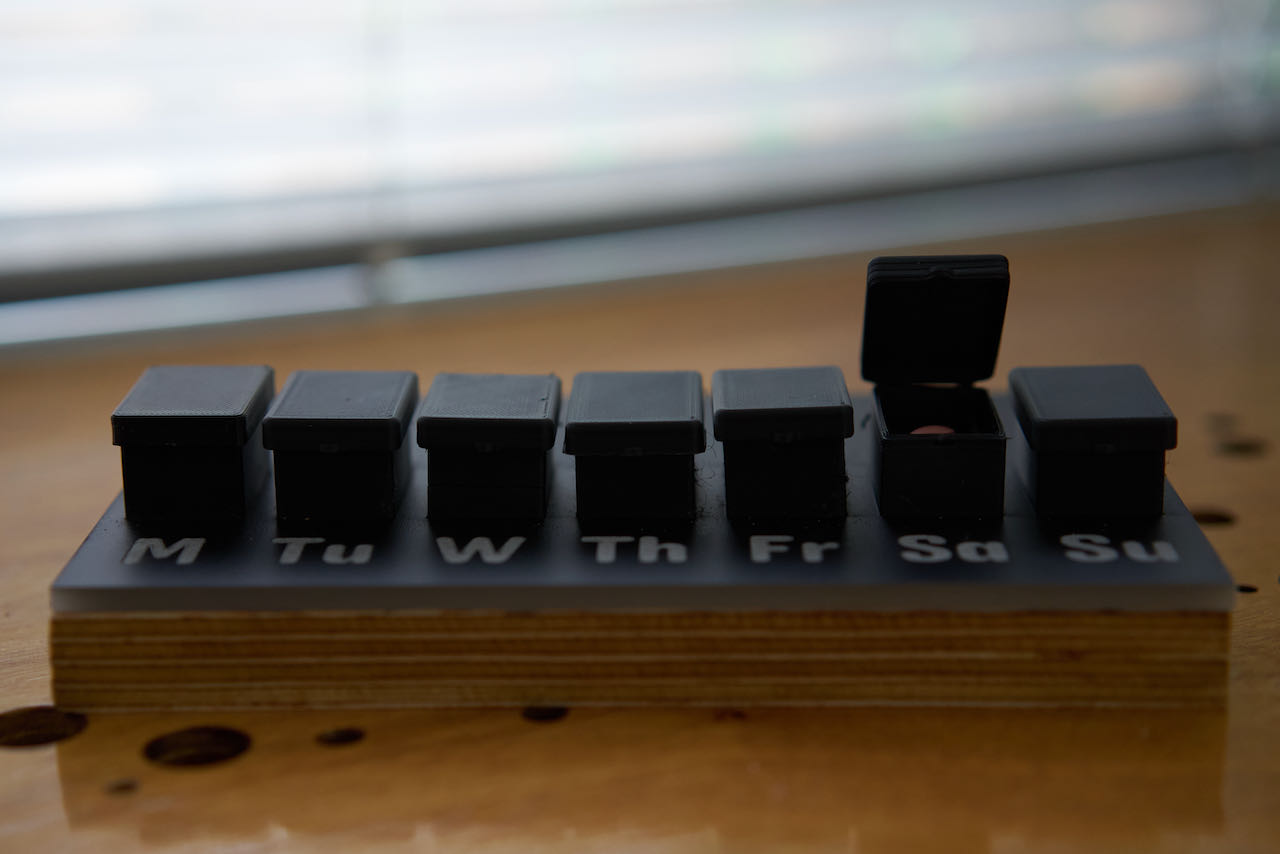
It makes me feel like a old lady in a caring home if i would set an alarm for it when to take it, 99% of the time i just take it in the morning and if i forgot if i did i can look in the box which is made up in days of the week.. but those times when i am already on my way to work or pleasure and i don’t remember if i took my pill, total panic.. i even ended up asking friends to pass by my house to see if the box of that day is empty. Now the logic answer would be: “schatje, just set an alarm when you have to take it then you wont forget”.. and thats exactly the problem, i don’t want an invasive intrusion in my daily life and even worse a reminder that i am “a patient”. In the 14 years i had to do this i tried many ways. trying to not have a constant reminder but still taking my pills in the 2 hour window i have. So finally a solution is on the way if i manage to make it work.
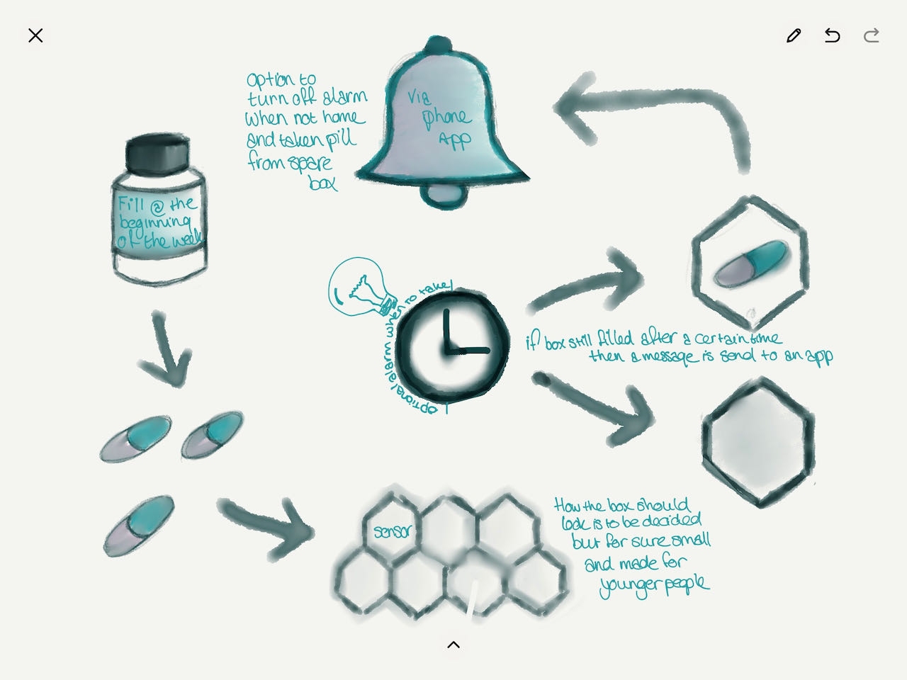
It would be great if i can optional set an alarm for when to take it, silent or not and when my window ends then a sensor would check the box, if that day is still full then a not so silence alarm is send to the app. So where ever i am i get a notification “hé trut, you forgot your pill”
some sensor ideas
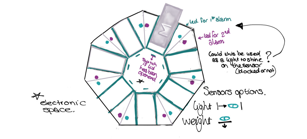
- a light on the bottom and a sensor on the top which has another benefit that the light can switch on when the pill windows opens as a short of alarm
- a switch that reacts on opening the lid this could also be helpful to register when the pills are put in there.
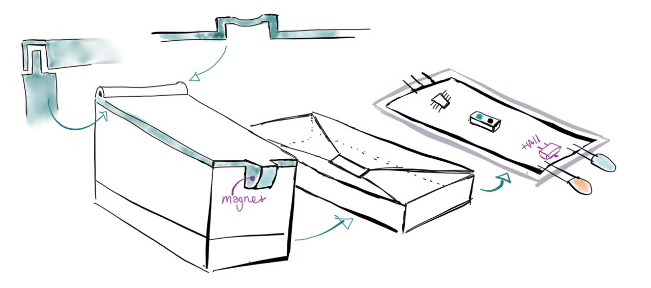
In Week04 i had a bit of free creative head space to think about my final project and realize it will have to be 1 box with 7 components which stay together, looking at other people trying to achieve the same thing i found out that to have take away boxes would make it bulky and way to complicated for me at the moment.
pills to go
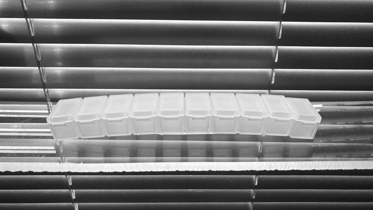
I also have another “pill” issue which is that going on travels i have a click together box but since it only connect from left to right and visa versa it ends up being a very unhandy thing to put in your bag. I would like to create a honeycomb click and go box. Made out of as many boxes as you have days to travel.. to a certain max ofcourse, i would say 10..
This spiral will have to wait till i have time, but since i have an Ender at home now and all the knowledge i learned the last 6 months i will be able to
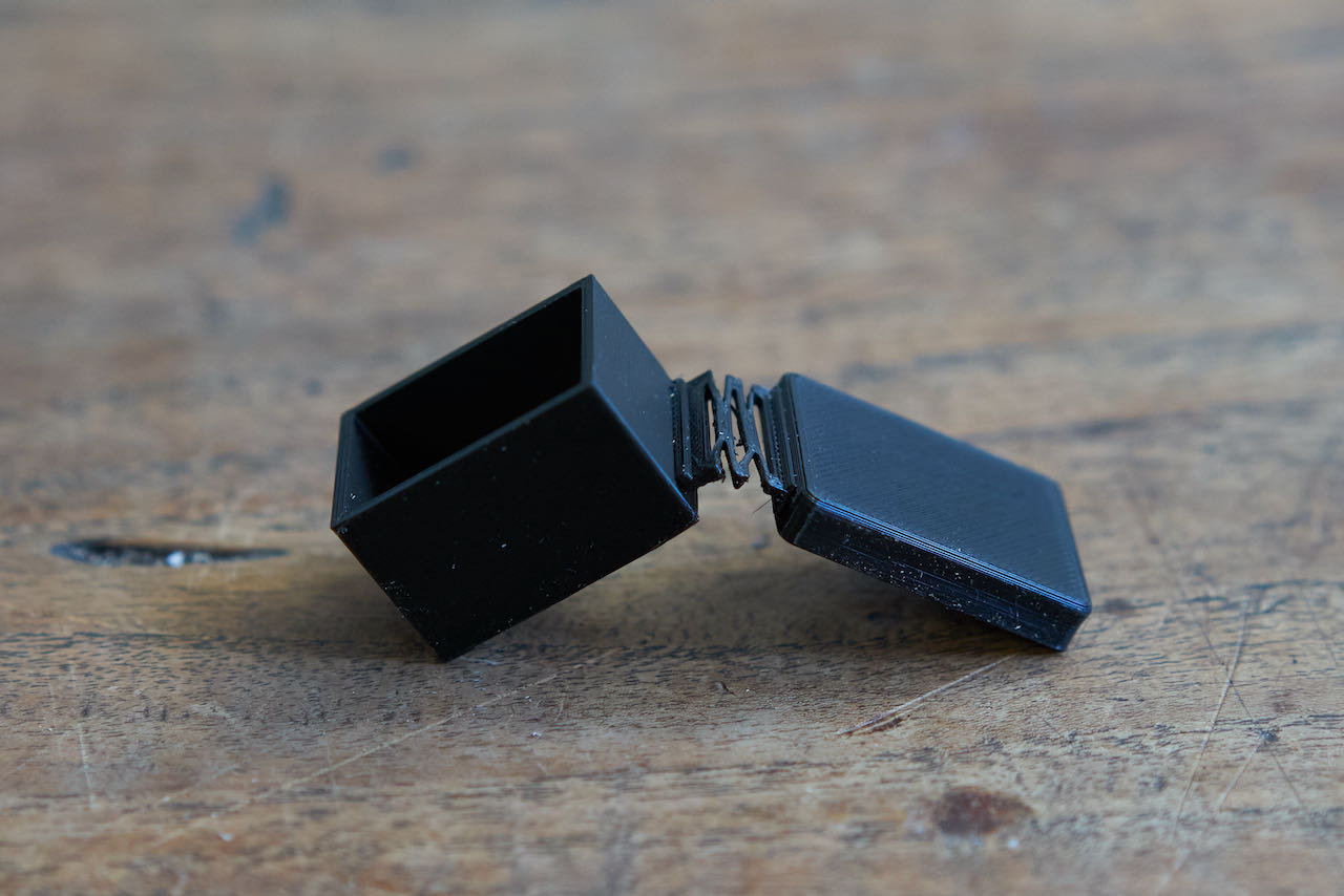
Opening form of the lid
There are so many ways to close the box, i would like to use a version where the lid stays attached to the box so that i wont be able to misplace it.
Living hinges
Living hinges are an effective solution when two rigid sections need to be joined together. Some of the advantages of a living hinge include:
- Low Cost - Because of their simplicity, living hinges are usually a much cheaper alternative compared to other hinge types.
- Durability - Living hinges are specifically designed to be opened repeatedly. They experience very little friction when opened and closed and this typically results in a long lifespan.
- Reduced inventory - Living hinges are integrated into a part eliminating the need for extra components.
- Appearance - Compared to other connection options (assembled hinges, snap fit connections etc), living hinges are an aesthetically pleasing and non-obtrusive connection solution.
The main limitation of living hinges centers around their inability to bear any load.
As with other 3D printed features, performance will vary based on design, material, printer calibrations and layer thickness. Because of this, creating the optimal living hinge for a specific design and technology is often an iterative process. This section offers several design recommendations that can be used as a starting point. Print direction
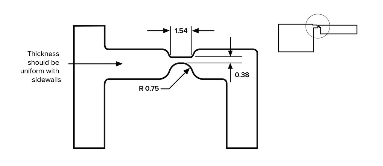
Due to the additive, layer-by-layer nature of 3D printing the parts that are produced are typically anisotropic (especially when printing with FDM). To ensure the performance of a living hinge, parts should be orientated so that the width of the hinge rather than the length is built up one layer at a time (the central axis of the hinge should be orientated in the z-direction). This will often mean printing the part in the vertical build direction, as shown in the image below.
There is a great site with explanation about the living hinches
And a tutorialsite about how to design it in Fushion
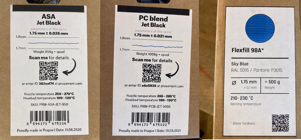
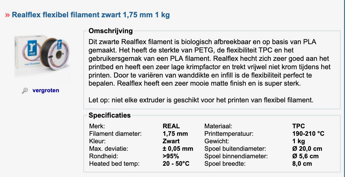
When i tried to print a hinch with ASA filament i broke very easy, ASA is an amorphous thermoplastic developed as an alternative to acrylonitrile butadiene styrene (ABS), which is to strong to be able to use as a hinch, although it makes a great stiff wall.. maybe combine the flexible with the one for the hinge or make separate pieces which i can glue together.

Material for the hinge/box
HDPE to be able to make a living hinge which i need to find out where and how to get it. HDPE is a plastic recyclable material and is easily recyclable. HDPE can be used as filament for 3D printers using Fused Deposition Modeling (FDM) technology. … but there seems to be some disadvantages:
- Limited resolution
- Poor adhesion strength
- High temperature nozzle and bed requirement
- Tendency to warp
- Doesn’t stick well
The hinge will have to be made from either nylon, TPE or polypropylene (at least that’s what the internet tells me)
Found a 123-3D print link to material that should be the right one to use, NYLON..
- Nylon (polyamide) is a versatile material with excellent thermal and mechanical resistance. It is suitable for printing functional technical parts with high temperature and mechanical resistance requirements. However, it’s very hard to print and therefore recommended for experienced users only. In large volumes, it has great mechanical resistance, while in thin layers it remains flexible. Its coefficient of friction is low, melting temperature is high. However, Nylon is hygroscopic, so it is necessary to keep it dry (airtight with desiccant). Improper storage can lead it to absorb water weighing up to 10% of filament weight.
Decided to stick to more realistic filaments which are hard enough to control.
in the meanwhile
Before the Nylon arrives i will try to make it work with material that’s for the beginner, except for the Flexfill which the material showed us by going into an enormous mess within the machine, so thankful that Michele was there and recognized the sound the Prusa made and was willing to spend an hour with tutorials and all to clean it up again..
I will not even try PLA since it’s so brittle and will break with the first bend.
ASA seems a bit to hard but it does great with details and is recyclable, another bonus point is that you can smooth it out with acetone vapor and or sand it.
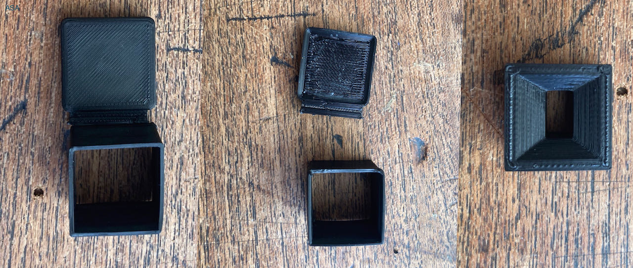
My first ASA try warped on the lid so made it a tiny bit thicker plus adjusted the size to a more fitting one for the pills i use.
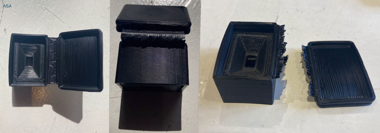
But the material is just not made for bending, i made the hinge a lot thinner and it worked for about 10 times and then broke.
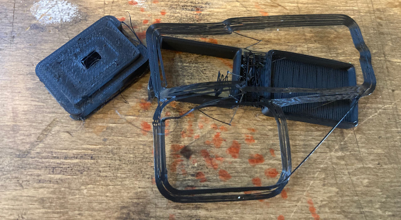
With the PC blend try out i got a big spaghetti which scared me a bit but if i see the specifications it seems very close to what i need.. although probably same as ASA a bit to hard. So decided to let it be.
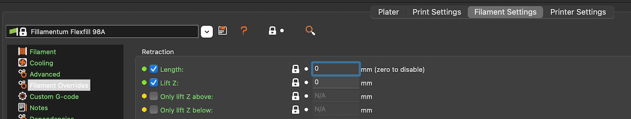
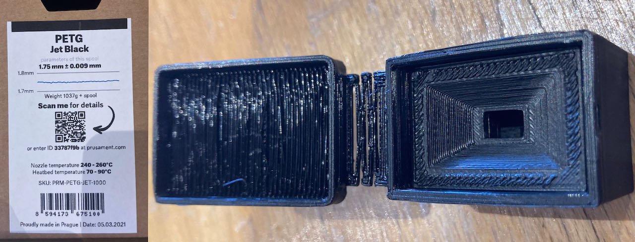
Here is the result of the FLEXFILL, the material seems very close to what i need, the hinge bends very nice and the small section i got out before it got stuck seems sturdy enough to function as a box
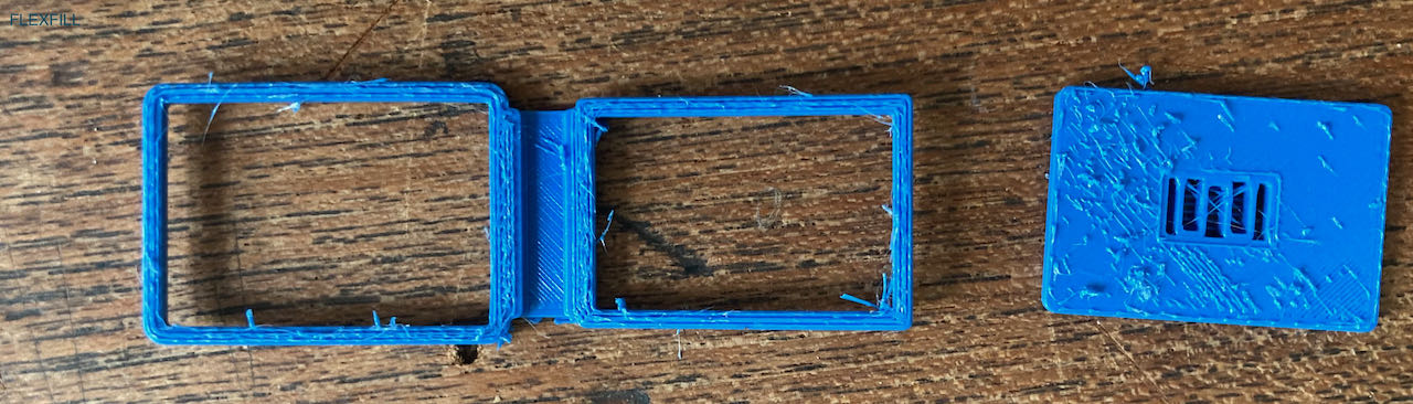
To avoid the filament getting stuck i used not detraction so it will not pull itself in spaghetti but the Prusa was still struggling.
Will give it a try on my ENDER with this new material i got the other day.
As i was trying all these material i got a better inside in my design, how thick and wide the hinge should be, shape and size of the inside box.
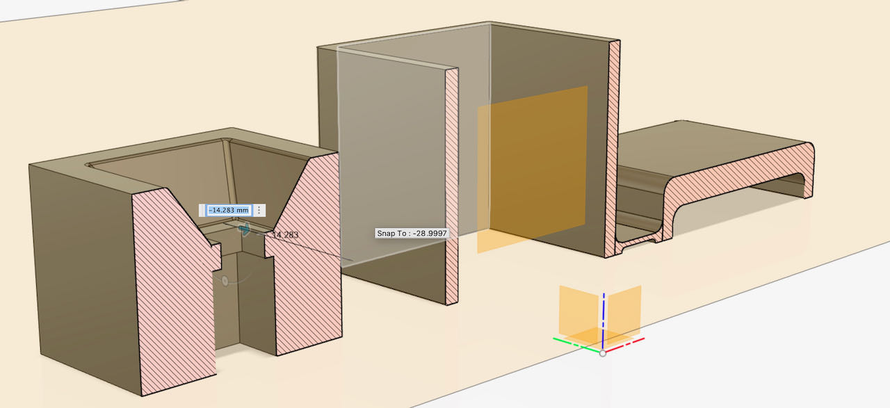
The first version was on the non practical long side of the box and to thick, so made it thinner and a changed the placement.
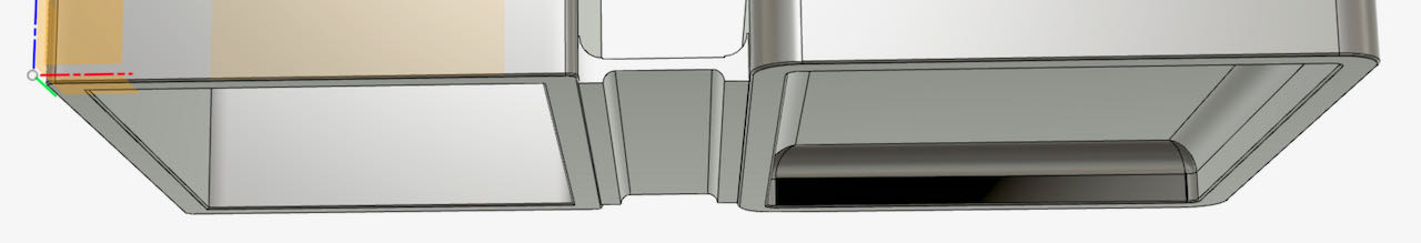
The last version has a bit wider hinge and also moved it a bit down on the box and up on the lid to make the curve fit better.
Finally had the time to put the ENDER3 together and download the Ultimaker CURA software, so now i can work from home once the filament arrives.
Since i anyways had to test the Ender i decided to use my just imported design and made Gcode in Cura for the Ender, there was filament that came with the machine which is not specified anywhere.. if i had to guess i would think it’s PLA..
Funky enough the hinch seems to work, but the walls are wobble and thin.. to be continued.
All the try out that didn’t make the cut.
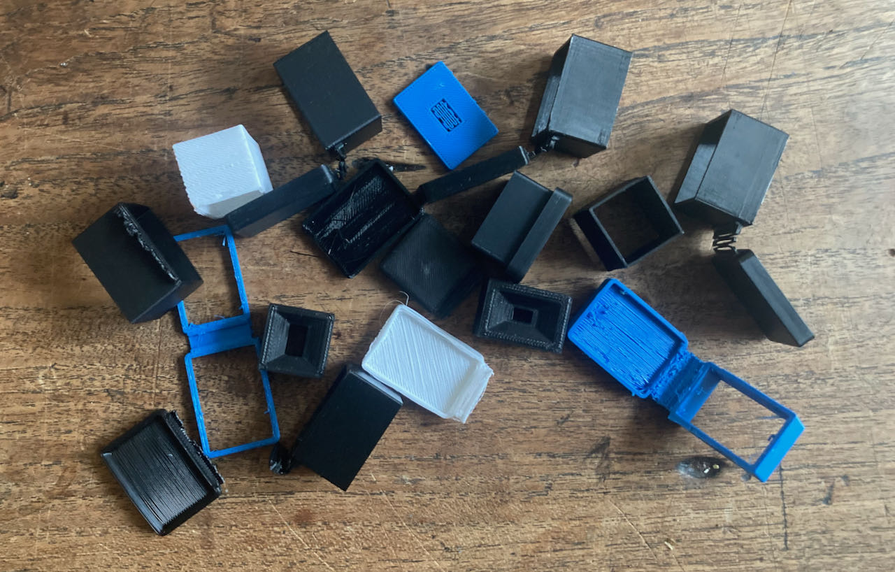
Real living hinges
Since this PLA box with bad settings for temperature and extraction (the layers were not connected very unstable and to thin) worked so well that got me thinking into different solutions.. why not use real living hinges like the one that Nadieh is using for her sidewalls.. a mini version may work.
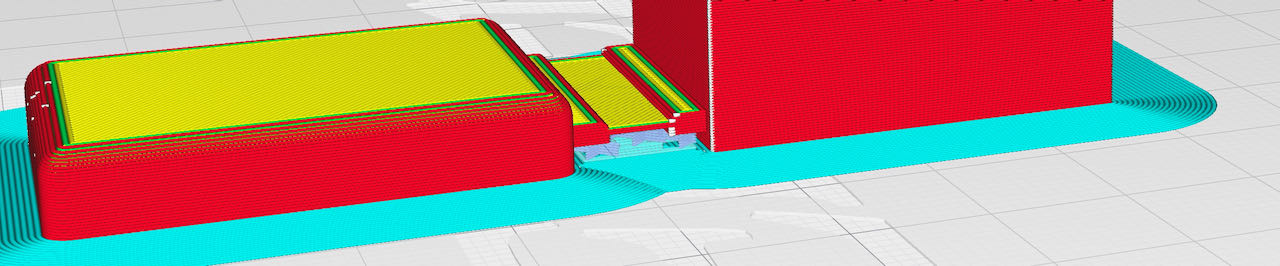
the cost estimated by Prusaslicer.
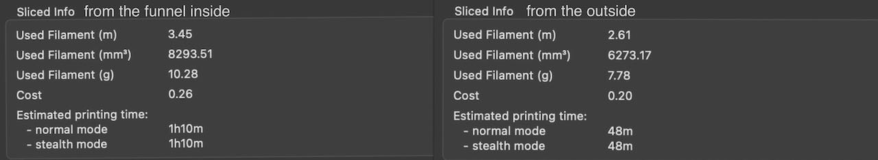
The first version had to much support material which was really hard to get off and seemed a bit to thin, so made a 1mm thick versions.
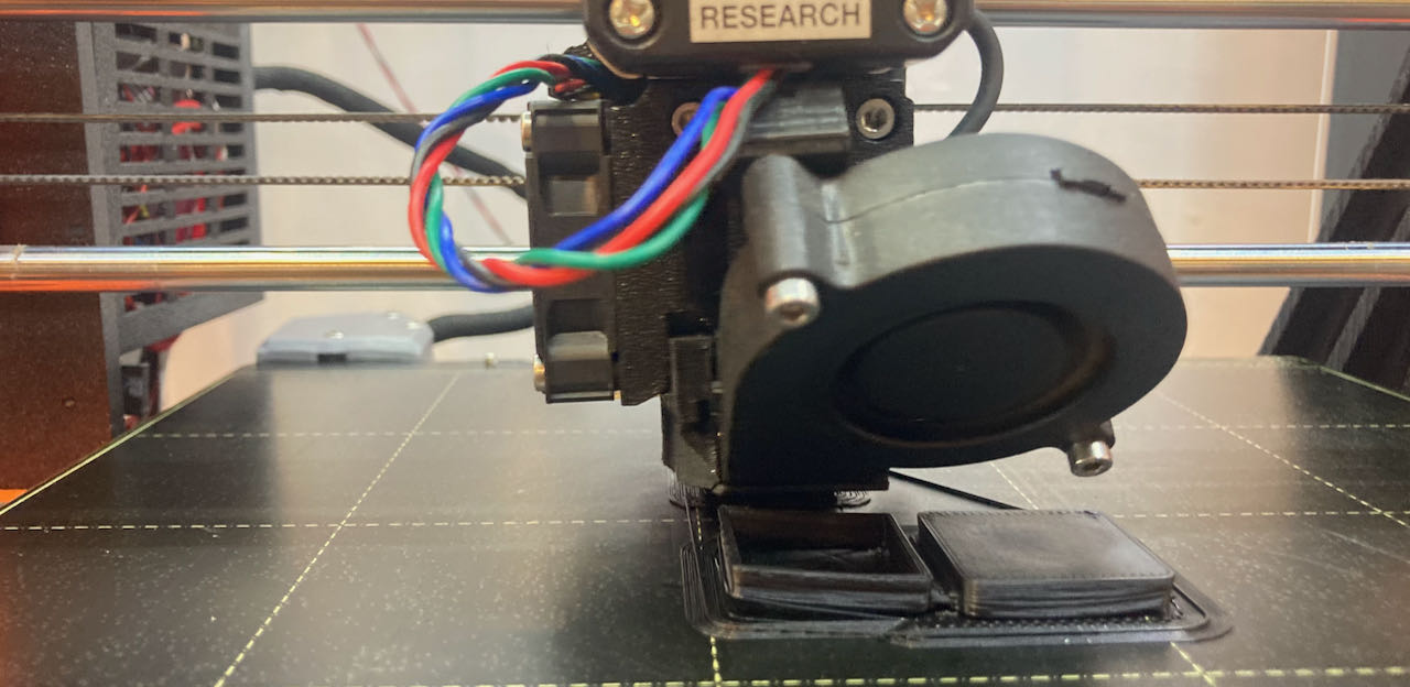
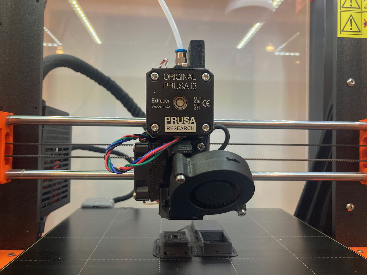
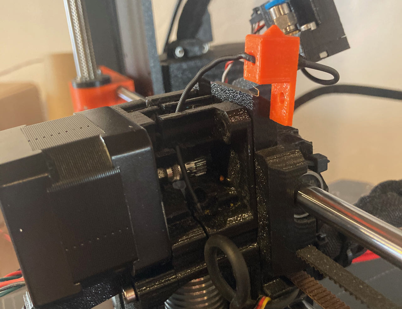
The 3D printing process in moving pictures
Got the filament so many times stuck in the Prusa that i stopped counting, learned a lot, mainly that it’s all fixable and the settings in Prusaslicer do make a big difference.
With the flexi filament the nozzle heat and detraction has to be so exact even if it’s fine one day it could be totally off another day, got me very frustrated but happy i stuck to the plan with my nice matte friendly to touch boxes. The way to notice before it’s visable that’s he is not extruding anymore is to listen, the machine makes a ticking noise when it gets stuck inside.
To end this section with a happy note a few shots of the final products.
Box
Slowly getting a clearer view of what it should look like, leaning toward the ready made KY033, spend some time already trying to figure out alternatives and whatever i make myself it will be a lot more bulky. I do know now how to make them which already is a big step for me.
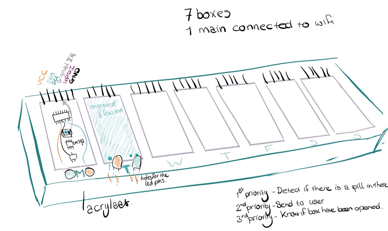
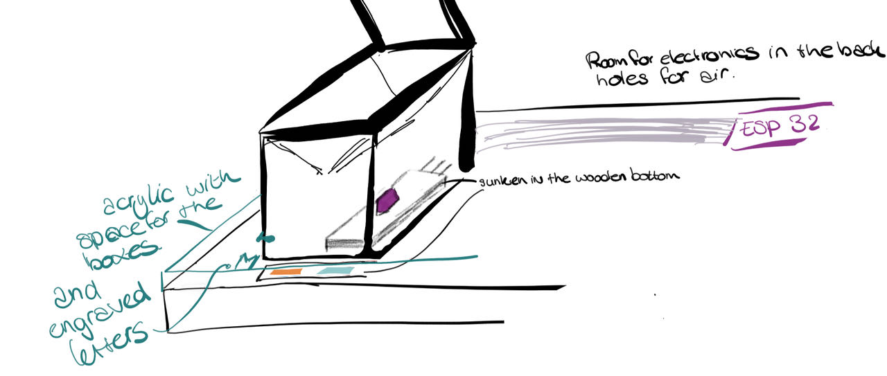
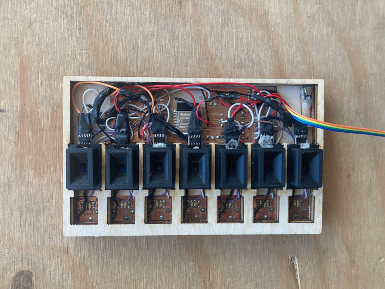
The bottom plate will contain all the electronics on which i place the separated boxes, on top of this comes a thin acrylic plate covering the LEDS (on that place letters will be engraved in the painted plate)
Bottom plate
I designed the bottom plate first in Fushion and the DXF file i imported in Vcarve.
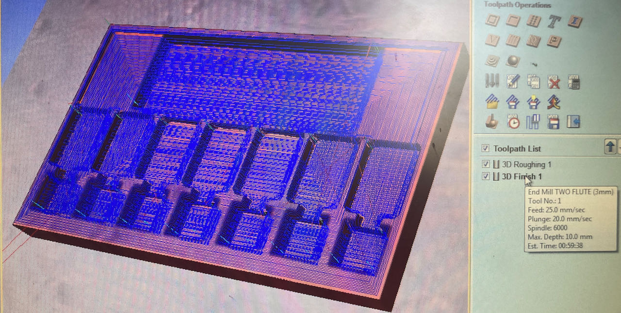
Settings Vcarve:
- 3mm 2flute mill
- speed 12000
- feedrate 20mm/sec
- step over
- roughing 80%
- finishing 20% took in total 1 hour to mill as you can see below in a timelapse.
It came out a bit rougher then i hoped so decided to try to make it work with sanding.
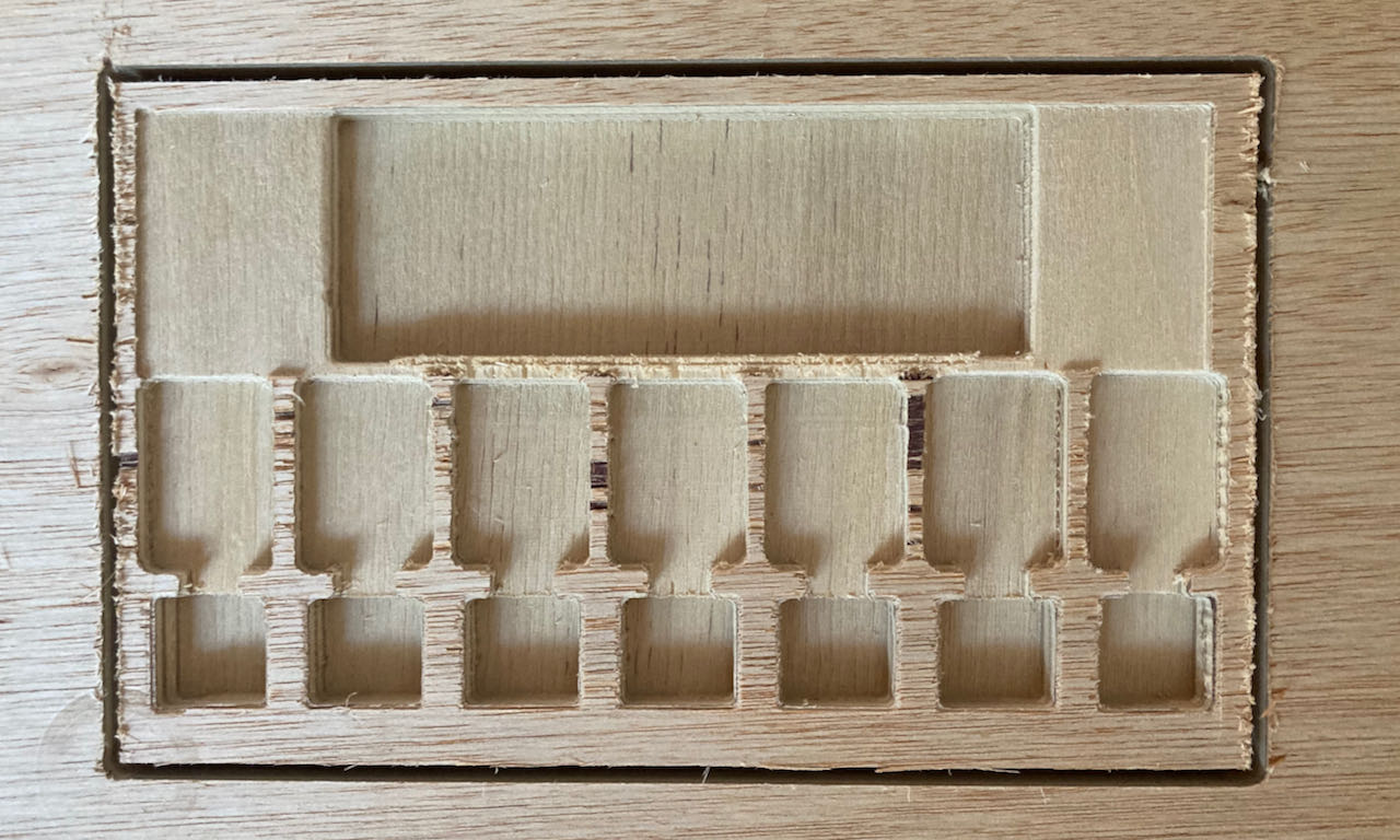
It did work a bit but when putting all the components in i realized i needed a bit more depth for the pins of the sensor to not touch and block the LED.. so they will have to turn around. did try to use my Dremel to make it work but my hands are just not as exact as a machine
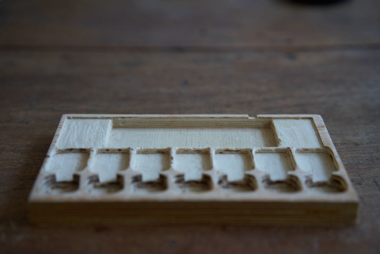
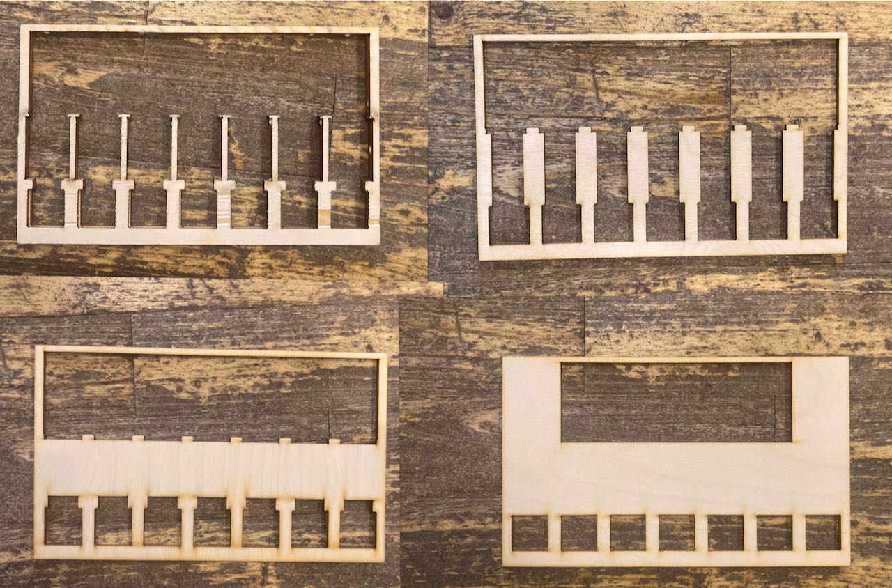
Since machine time is limited these last days till the presentation i will do everybody including myself a favour and lasercut the layers and make my own multiplex :)
Top plate
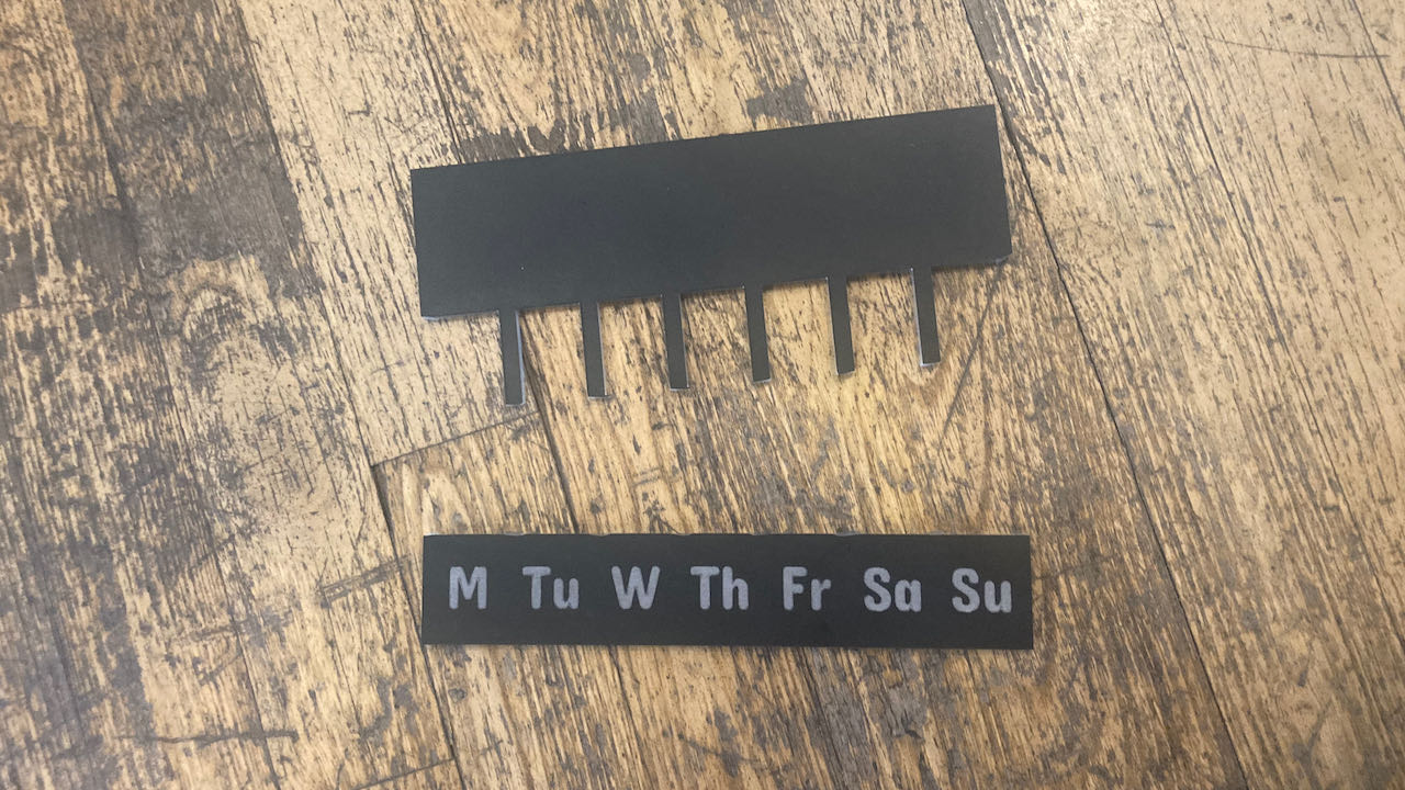
The top plate will be from painted acrylic with lasercut engravings to see the leds shine through at the assigned day.
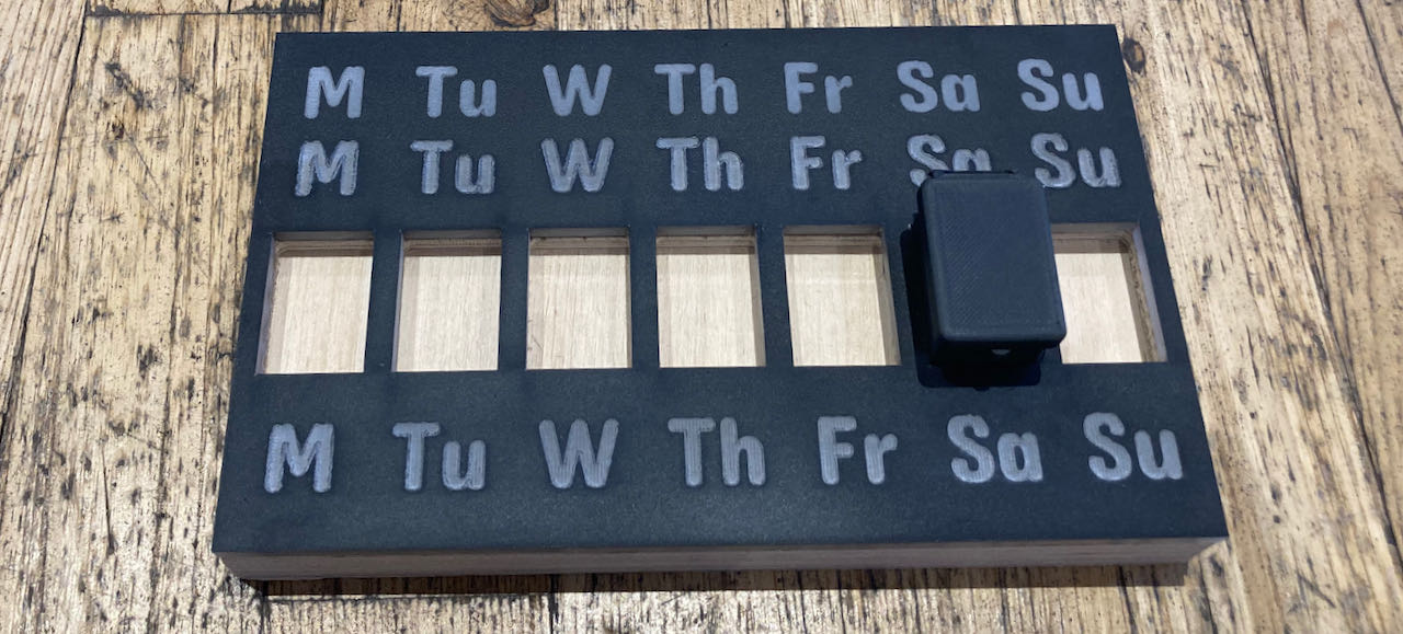 Designed the file in cuttle, easy and quick, time is limited these days. Spray painted the plate with matt black and tried to version, i decided not to use the soap that recommended everywhere online because it was working just fine without is.. well at least for what i wanted.
The setting i used on the lasercutter:
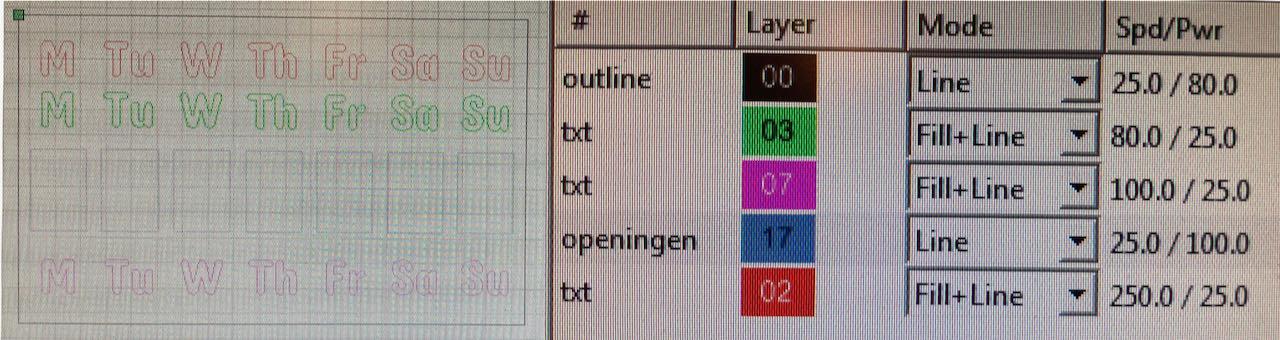
and the final product:
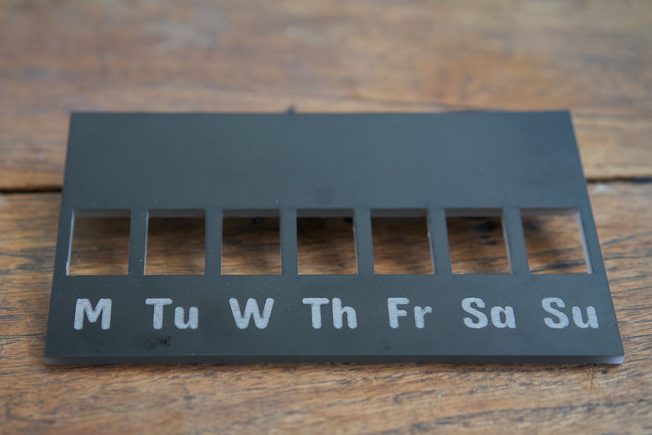
Note to self.. if acryl doesn’t seem to fit stop pushing.. it fitted with the bendable empty boxes but with the sensors in there it just would not fit , only 0.5mm.. but enough to break it
Electronics
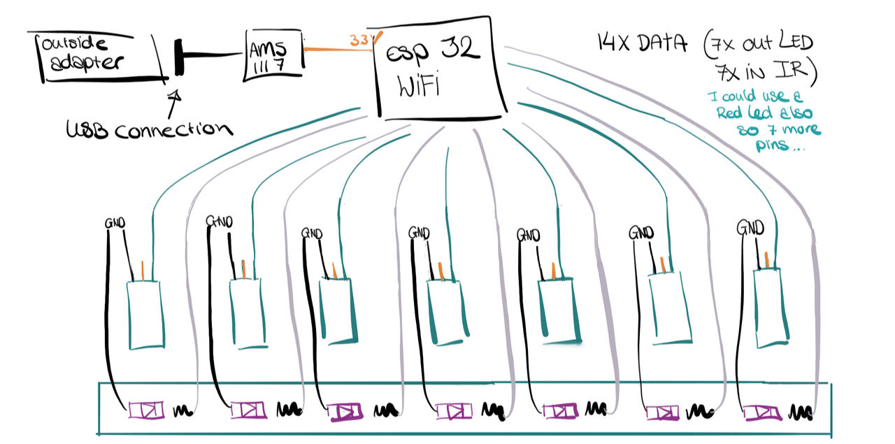
The overall schets will be something like this:
LEDs
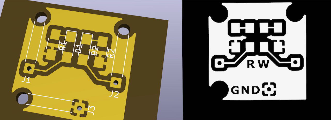
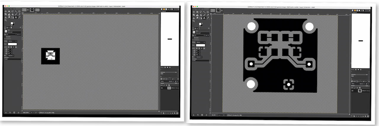
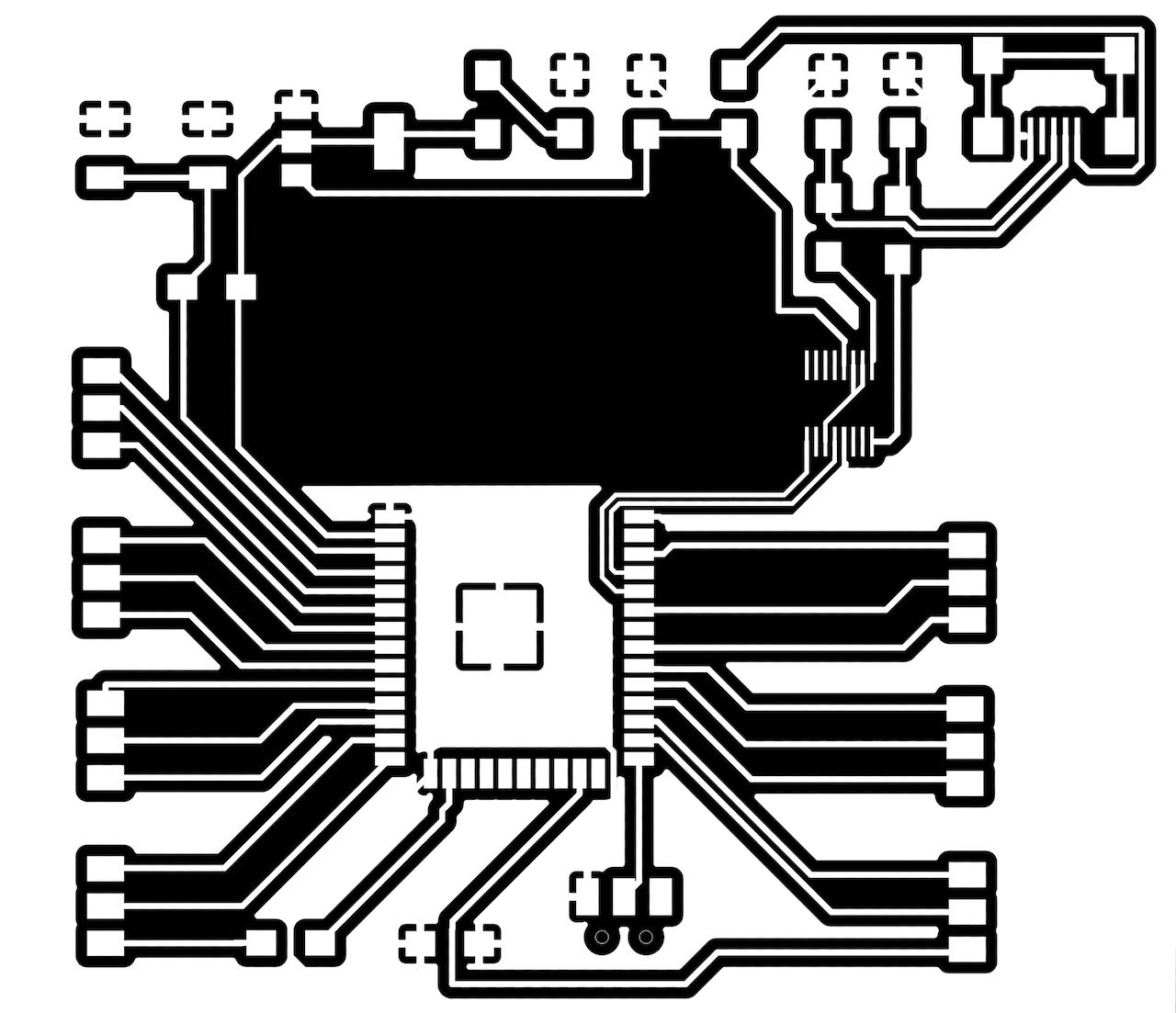
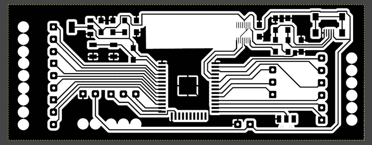
Tried to follow the official kicad path of exporting files via plot to make sure i had the hole exported but ended up with very small images which i didn’t wanna spend time on figuring out why since time is running way to fast these days, so i will stick to the importing the copper layer in Gimp and take the drill holes from there. Probably a bit less precise but it does the trick.
Got a bit of an accident with a mill that was either not 0.4mm or had a bit of a crooked point.
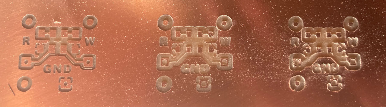
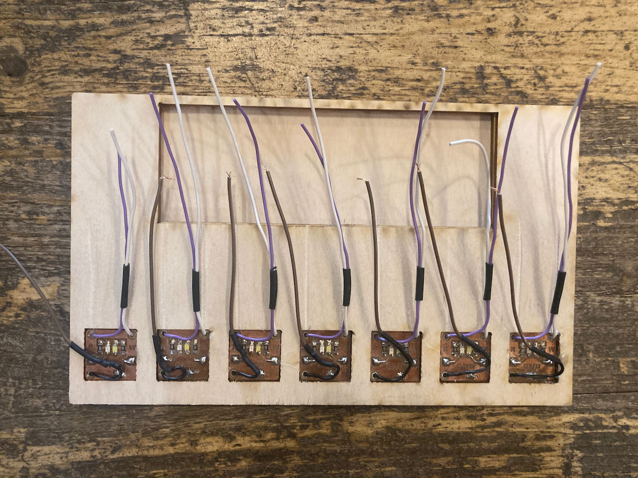
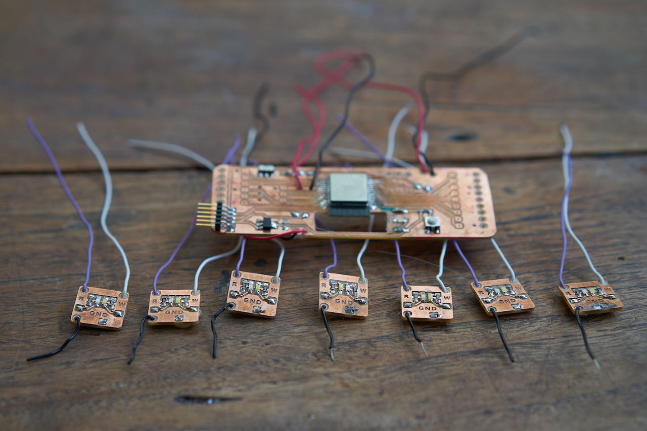
But managed to get all 7 off them out in the end, as you can see below with me soldering them and adding some hotglue to make sure the cables don’t get undone.
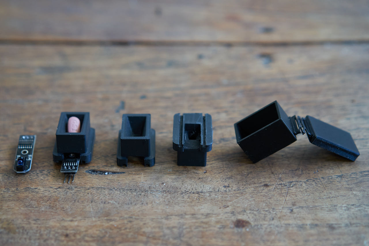
Sensors
Due to time pressure i decided to use the ready made KY033 - also since i know i can make them and understand how they work since i spend a lot of time researching and creating my own in week 14
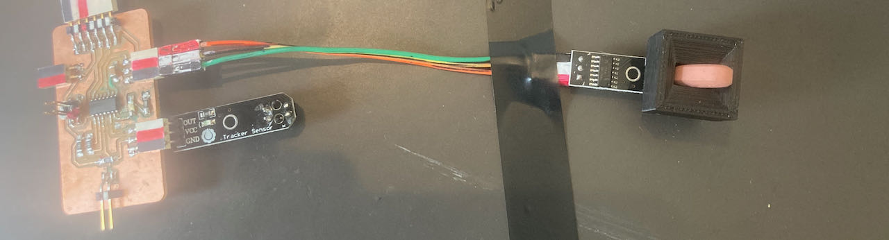
Made a little setup to check my box shape, the KY033 fits like a glove in the hole.
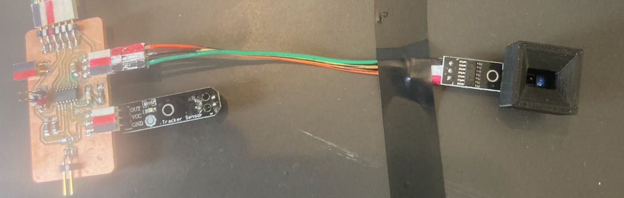
And the sensor seems to be on the right distance from the subject, works like a charm.
I only need to find a solution for this.. the pill can fall inside the hole, maybe a little grid or the simple solution make the hole a bit smaller.
After resoldering the wires (i had to cut off the pins that were taking to much space ) i checked again if they all still worked.. good thing i did, had to resolder 2 of them.
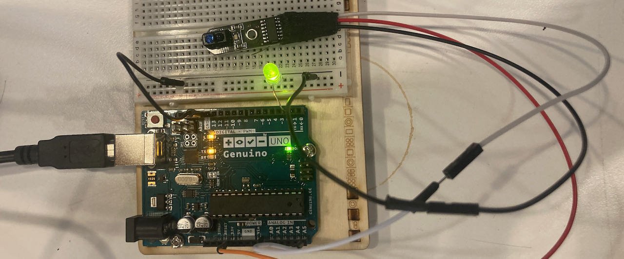
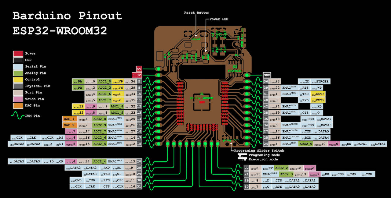
ESP32 with WIFI
The ESP is a bit to big but very useful because of it’s WIFI possibility. It has way to many pins for what i need so i could actually consider using 2 colors of LED.. one for the window and one for the missed my window.
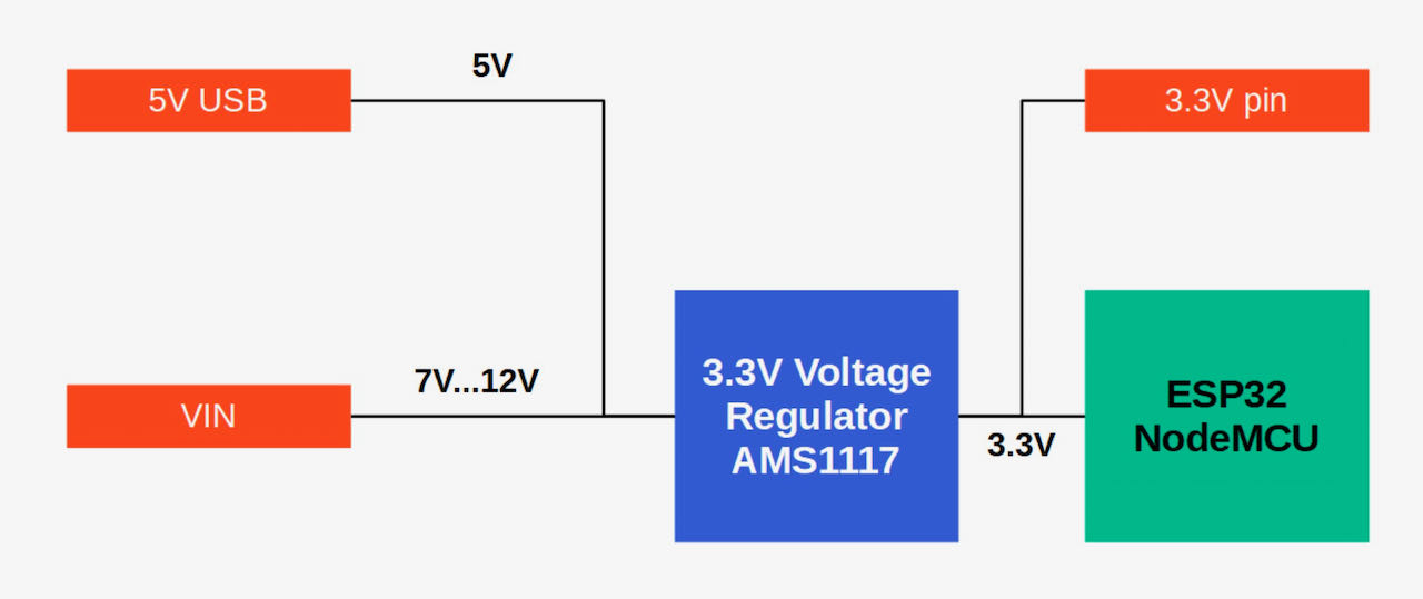
It works most stable on a connection of 5Volt which can be converted to 3.3V
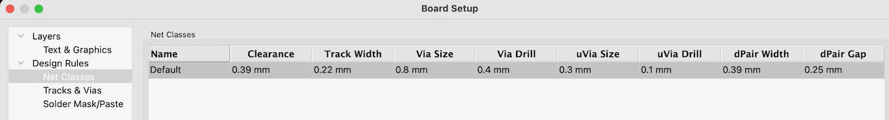
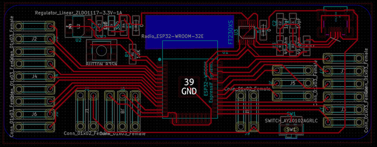
designing the board in Kicad
Henk suggested to me to start with Neil his board set up for an ESP32 so that’s what i did and soon realized i want something a bit user friendly otherwise i will have to take my board out every time to connect the RX and TX so that i can programme.
Ofcourse there is also still the option to programme over air which i documented here in Nathan his final project - this i will have to make a separate spiral from first focus on making a board.
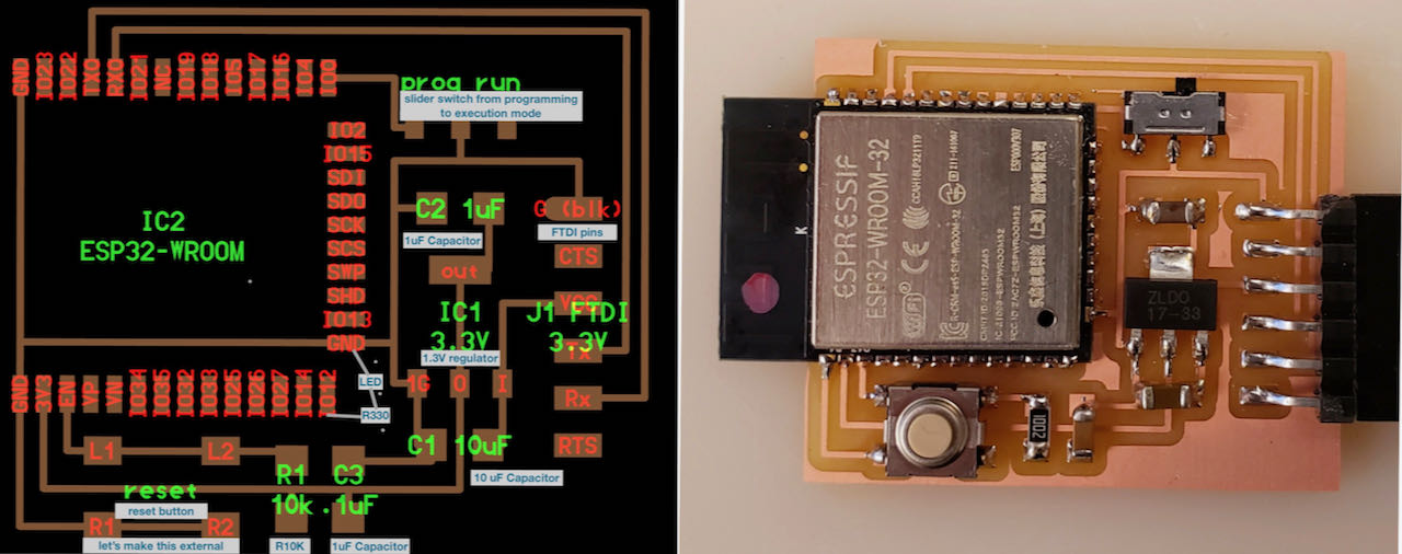
The fablab in Barcelona already spend some time on creating a board to make it easier to work with the ESP32, which is documented here on this Barduino gitlab repository)at first i only found the original which also still need to be programmed with an external FTDI..
Thankful that they continued to develop and ending up with a 2.2 version, which is documented on this gitlab repository. The great thing about this version is that they only use a mini usb connection to programme and power. I tried to download the Kicad files but with a missing library (only found that out later) it was not so so practical.
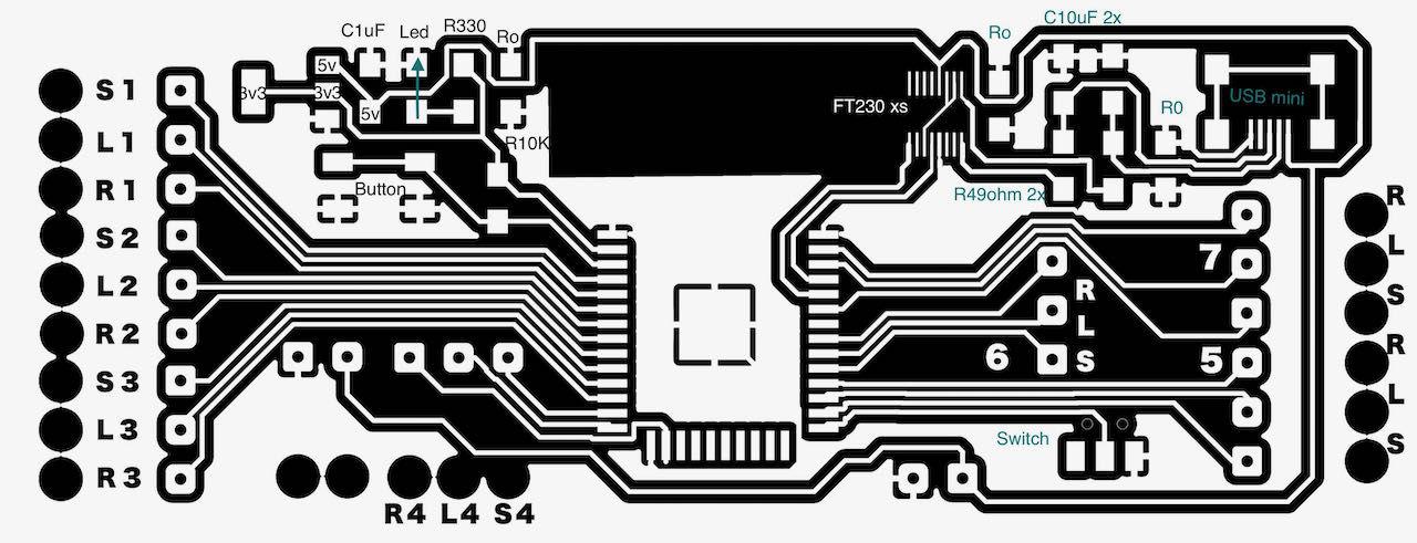
ESP32 with FTDI and USB mini connection (based on Barduino 2.2)
Decided to make my own, since i anyways need to alter a lot to fit it to my specific needs, at the moment a bit stuck on my way to the Waag to find out what component we have so i will use the right footprint. Also a bit confused with the FT230 footprint, if i leave my board setup on 4mm width i can’t connect the pins, need to experiment a bit what works best, don’t wanna mill such a bit PCB and end up not being able to solder the UPDI on.
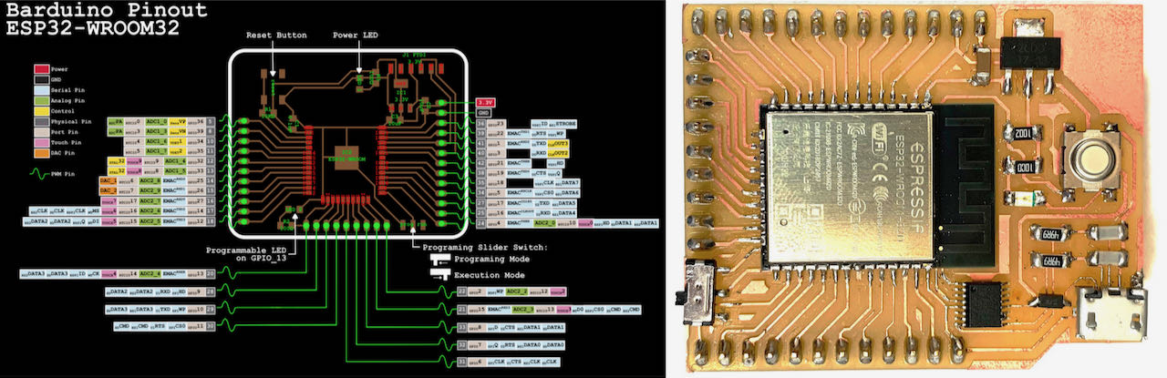
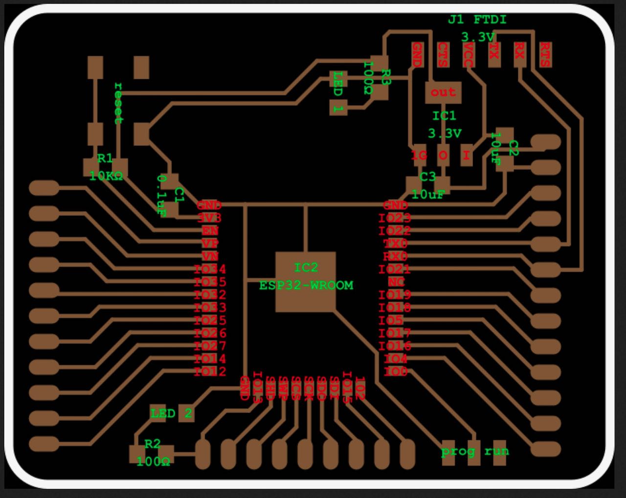
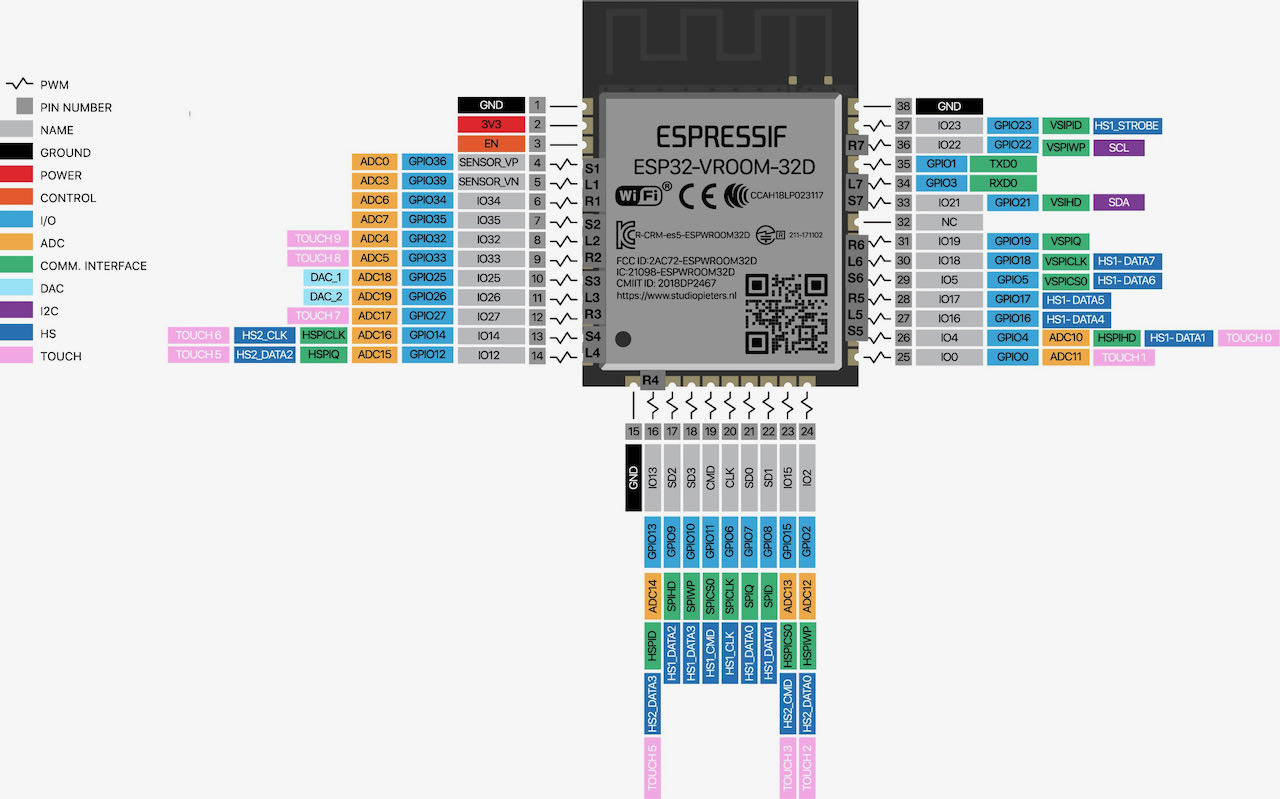
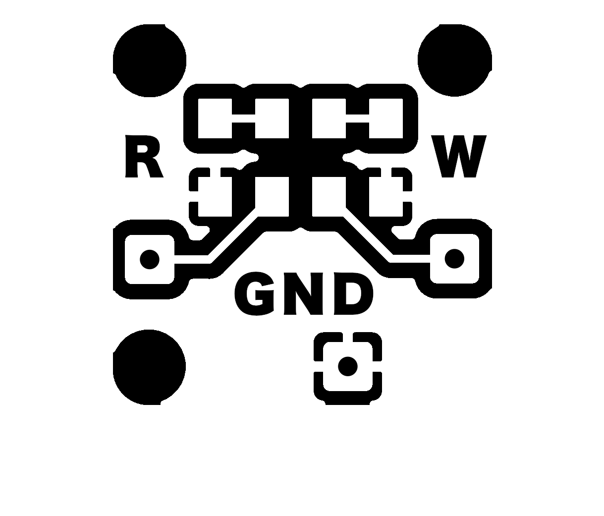
The pinout drawing helped me a bit to figure out the traces and component footprints.
The first design seems very bulky and to square, need to get a better view on how the ratio should be. So will create a mock up today to give myself an overview.
Thought it would be smart to add a little strain relief to the wire connections so imported the rest of the kicad library and used this wire connection. Ended up tweeking it a bit to my own liking but was a good place to start with this footprint.

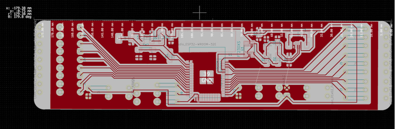
OK, it all fits but now it’s to big to fit on a milling plate, the one at the waag are 127mm wide, back to kicad.
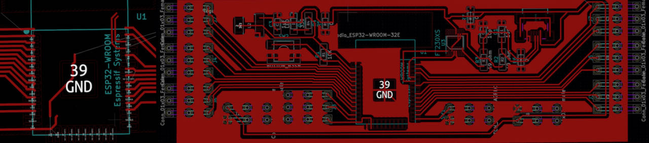
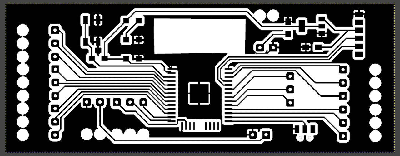
When importing in Kicad you can see the size, below from the big board and the small LEDs.
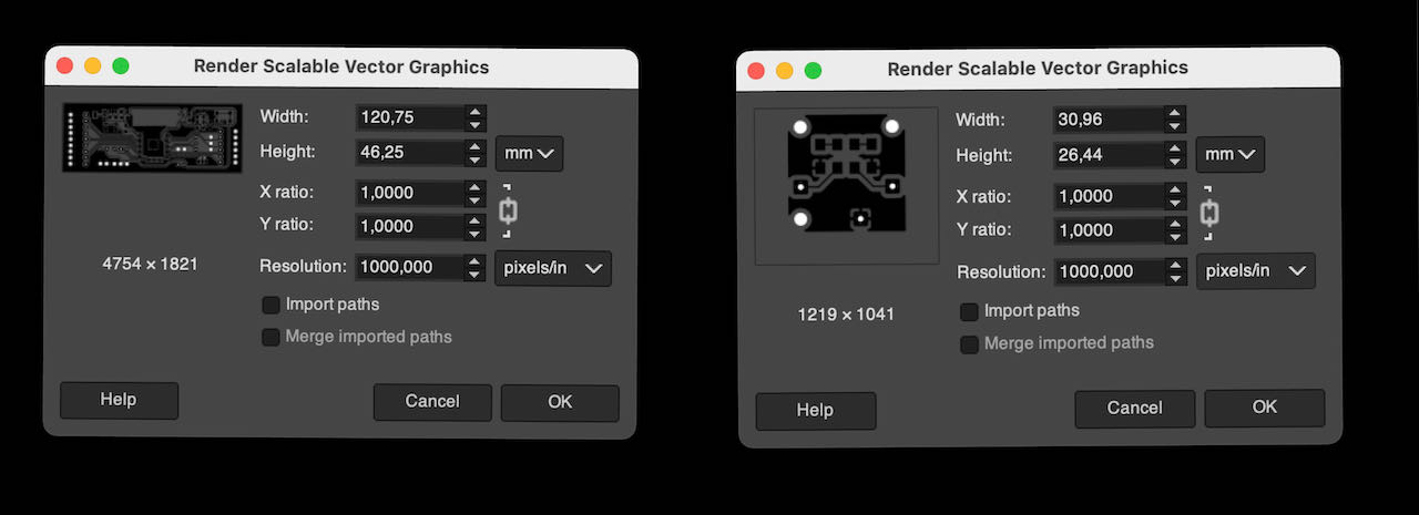
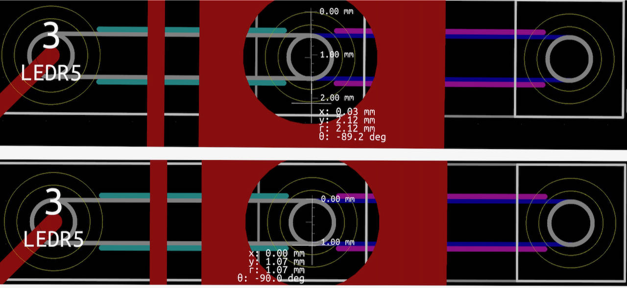
When i had tried to make the size fit better i got a message from a fellow student about the ESP32 footprint which made me look at which one was i actually using. It selected the original ESP32E wroom from the kicad library when actually i should have used the fab version, since they made the pads fit the 0.4 clearance that we need for our 0.4 mm mill. Below you can see the space in between the pads was to small on the original.

Hmmm.. if i have this issues with the ESP maybe i should check my FT230, the footprint was fine but i realized i needed to be a bit more exact on the clearance and temporarily changed my board set up to draw the traces to the FTDI chip.
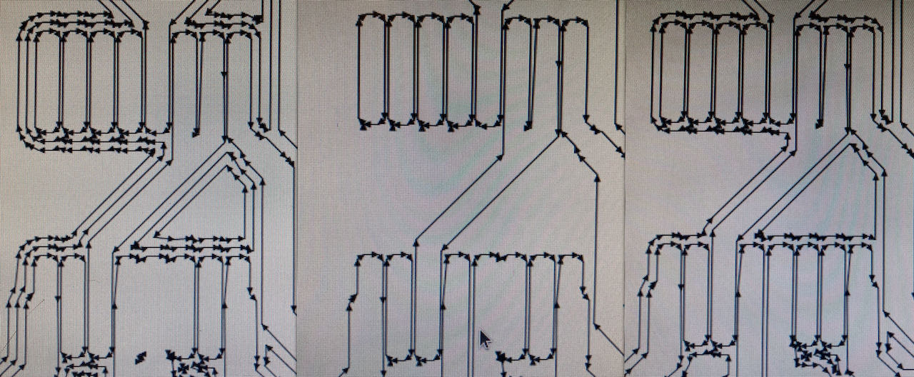
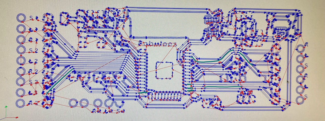
 When importing in MODS i noticed that it still went wrong, anyways need to remill due to sticky traces, so will spend another few hours on making sure the traces are not to close together.
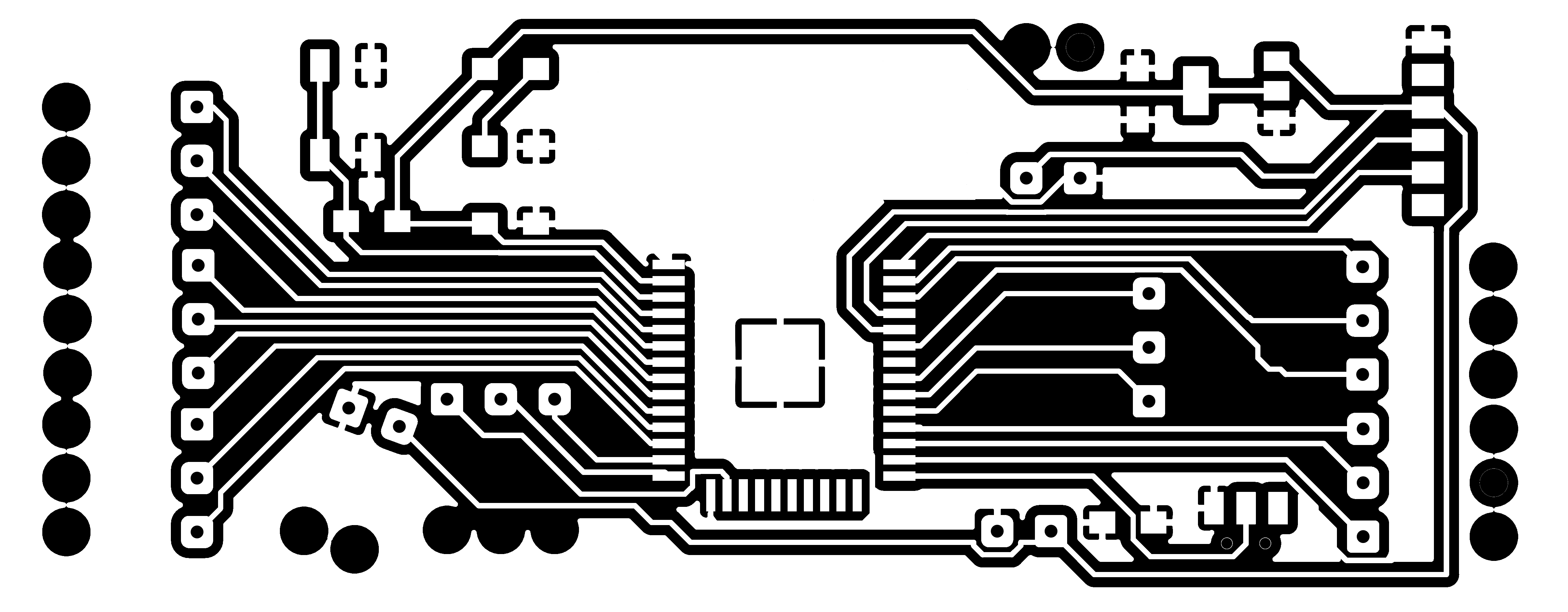
Finally got a version together that fits on a plate and it not to wide but still has the strain reliefs.
 To make my life easier i got into the habit of drawing out the components on the traces png.
 I could have noticed here already that a few mill paths were missing if i would have paid more attention.
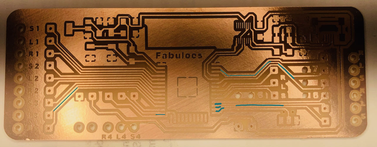
When i cleaned my pcb i finally noticed the sticky traces.. time for glasses and an focus workshop?
From the footprints i got the list from components
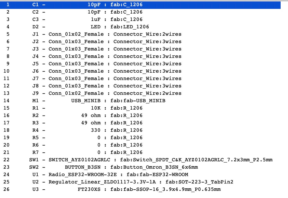
Made a new Kicad design with wider traces and looked through all the components to check if i missed something, fingers crossed. Also decided to cut out the place underneath the antenna to make sure i don’t get to much interference.
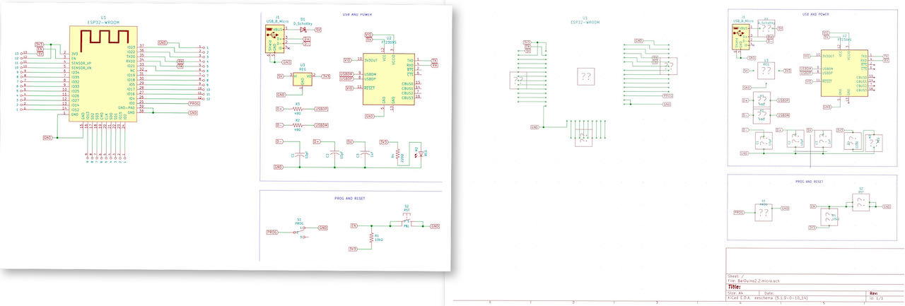
ESP32 without FTDI (based on Barduino)
Figured that since i couldn’t even get my board to be recognized by the computer i figured a back up plan would not be a bad idea so made a simpler version without the FTDI, just not sure on how to power it, but pretty sure its doable, hopefully don’t have to go to this version, the ideas was to push myself during fab :)
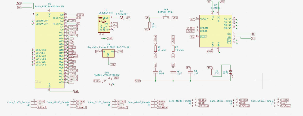
the original schematic:
My version:
After a talk with Henk decided to go for the simpler version, at least like this i have a change to actually finish this week, a bit off a bummer but maybe it means i will have to make a version 2 in the future.
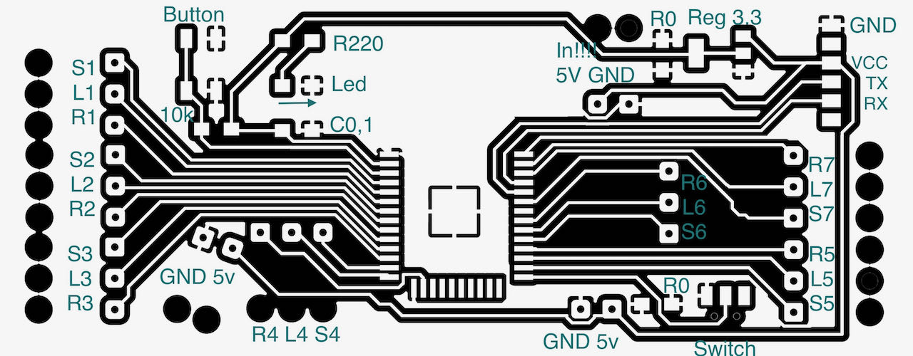
the pinout of the ESP32 with my number written on it for reference while programming.
Here you see the Roland iModela milling happily away
and me trying to solder this big esp32 with tiny feet on there (first measuring ofcourse)
Tried to make the connections as secure as possible with strain relief and additional hot glue to hold the wires in place.
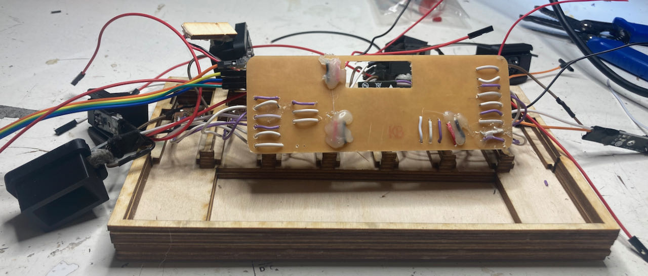
It all fits nice together although for the next version i would distribute the GND differently, going from PCB to PCB instead of having a bunch of wires that have to be connected together.
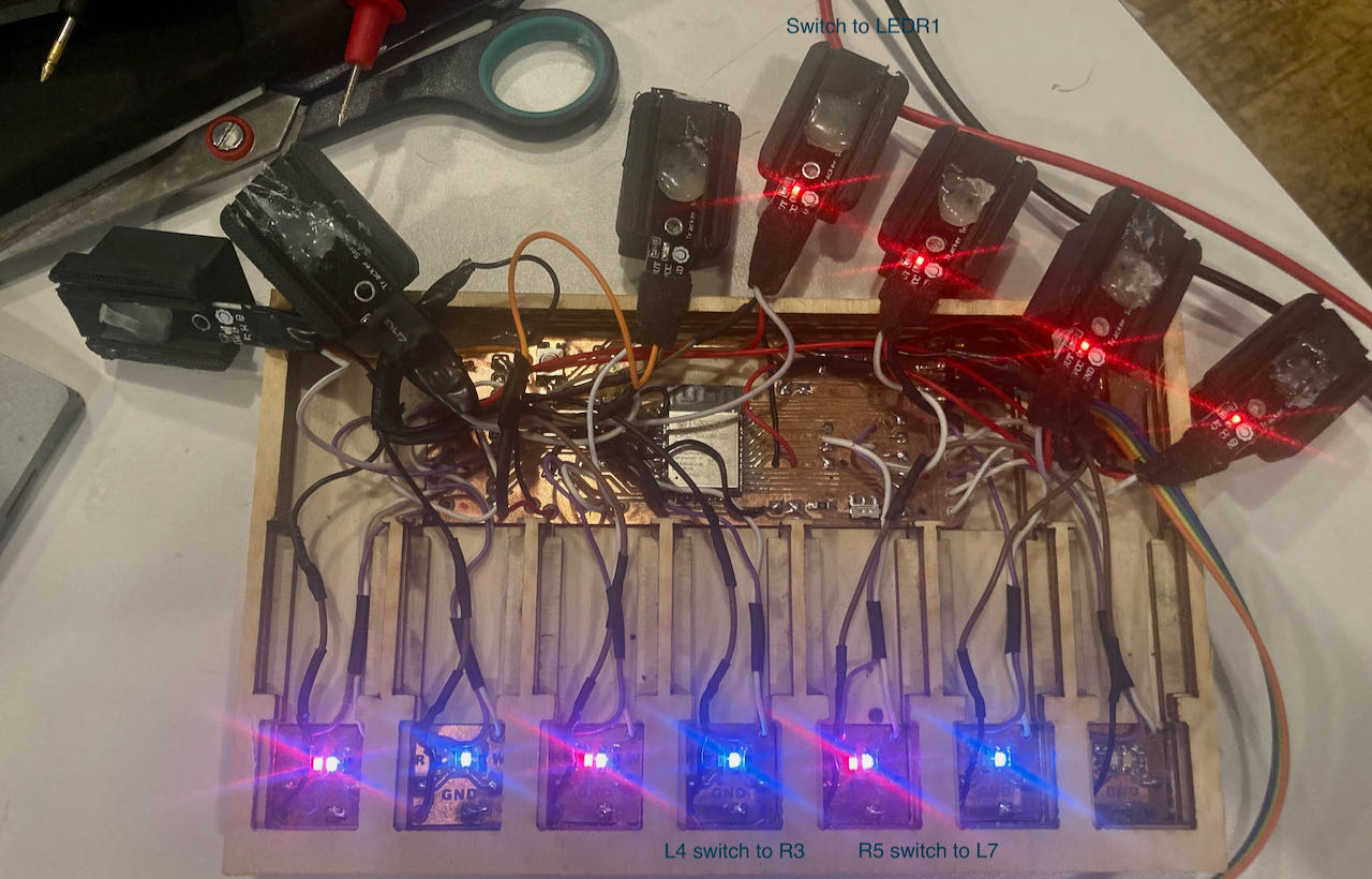
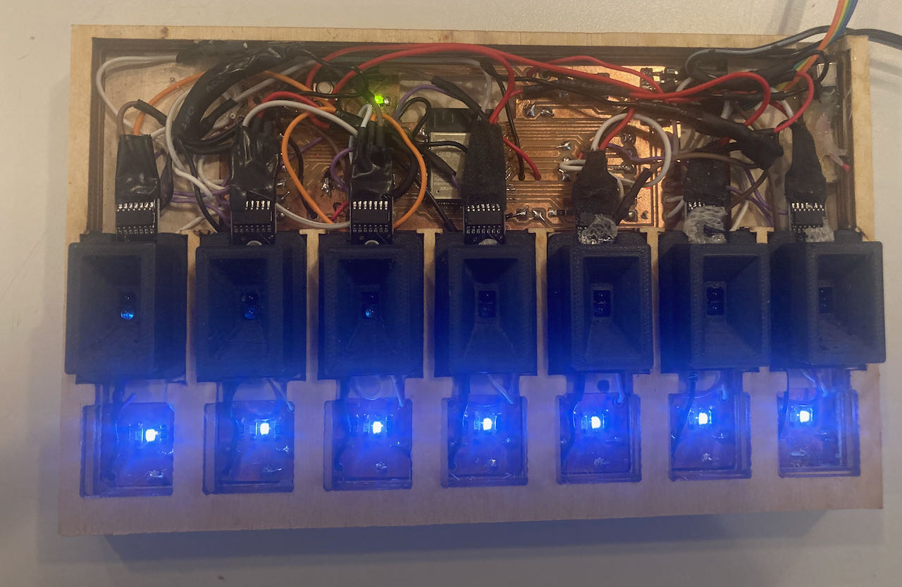
Ofcourse not all the connections were working prperly, instead of loosing time fixing this i decided to kick out the red leds for this version and at least have all the white LEDs and sensors connected so i can start to programme.
That worked :) so now on to the chapter of programming.
Programming
In my own words:
-
7 o’clock (a loop of 24 hours since the week days never change)
- the white led should go on.
- every 5 sec the sensor should check if there is still a pill in there
- if there is no more pill the white led should go off
-
10 o’clock
- f there is still a pill in there, the red led should switch on
- at the same time an email should be send to me warning me.
-
at 7 the next morning
- the red led should switch off even if there is still a pill in there.
then the cycle starts again.
AT first i had to get the ESP to work, i tried many uploads all failed this i realized i should not use the shift - command - U since that is upload with programmer which we needed with the Updi but not with the FTDI/ESP.
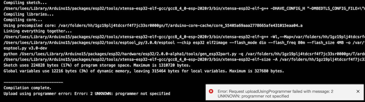
I got frustrated and decided to safe it for monday together with Henk, which was a good idea, it worked like a charm on his computer which gave me the confidence to continue this road
and with succes.
First define all the different libraries, leds and signals:
//include for time synch
#include <WiFi.h>
#include "time.h"
#include <ESP_Mail_Client.h>

//define the leds (1 is monday and so on)
const int L1 = 26;
const int L2 = 33;
const int L3 = 12;
const int L4 = 13;
const int L5 = 18;
const int L6 = 22; //Possibly used by WiFi
const int L7 = 19;

//define the reflection signals (1 is monday and so on)
const int S1 = 25;
const int S2 = 35;
const int S3 = 14; //Possibly used by WiFi
const int S4 = 27;
const int S5 = 5;
const int S6 = 21;
const int S7 = 4;

// initialize the signals value:
int SS1 = 0;
int SS2 = 0;
int SS3 = 0;
int SS4 = 0;
int SS5 = 0;
int SS6 = 0;
int SS7 = 0;

// these are some definitions to program with:
bool pil_taken = false;
bool email_send = false;
int current_day = 0;

unsigned long previousMillis = 0; // will store last time LED was updated
const long interval = 500;        // interval at which to blink (milliseconds)
int ledState = LOW;               // ledState used to set the LED

////////// WIFI //////////
//network name
const char* ssid     = "myWIFInetwork";
//password
const char* password = "MyPassword";
The definitions to program with only came later in the process when i got the help of Nadieh to put everything together. I was able to find all i neeeded but to be able to combine all the definitions i needed an extra eye and brain, programming takes practice.
Found this great random nerd tutorial on getting time and date from a NTP server,
/////////// TIME ///////////
//timeserver
const char* ntpServer = "pool.ntp.org";
//difference between your timezone and GMT in seconds
const long  gmtOffset_sec = 3600;
//the amount of sec for daylight saving time
const int   daylightOffset_sec = 3600;

//Will contain all the time info
struct tm timeinfo;

const int start_hour = 9; //When should the program start checking for the pil
const int check_hour = 2; //How many hours after start_hour should an email be send
getting the time was fairly simple:
  ///////// TIME /////////
  // Init and get the time
  configTime(gmtOffset_sec, daylightOffset_sec, ntpServer);
  getTime();

  // //disconnect WiFi as it's no longer needed
  // WiFi.disconnect(true);
  // WiFi.mode(WIFI_OFF);
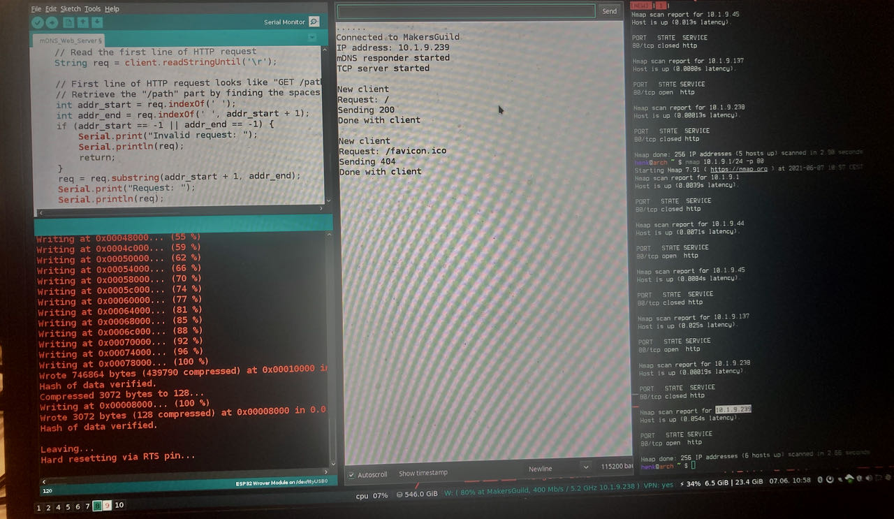
But ofcourse it first has to be connected to wifi, added some reconnecting and serial print to understand whats happening under the hood.
  ///////////////// WIFI /////////////////
  // Connect to Wi-Fi
  Serial.print("Connecting to ");
  Serial.println(ssid);

  // WiFi.disconnect();
  // delay(1000);

  //Show networks
  byte numSsid = WiFi.scanNetworks();
  Serial.print("Number of available WiFi networks discovered:");
  Serial.println(numSsid);

  for (int thisNet = 0; thisNet<numSsid; thisNet++) {
    Serial.print(thisNet);
    Serial.print(") Network: ");
    Serial.println(WiFi.SSID(thisNet));
  }

  //password and network obtained from definitions
  WiFi.disconnect();
  delay(24);
  WiFi.mode(WIFI_STA);  //modus to connect to a wifipoint
  WiFi.begin(ssid, password);
  delay(3000);

  // int del = 500;
  while (WiFi.waitForConnectResult() != WL_CONNECTED) {
    Serial.println(WiFi.status());
    Serial.println(wl_status_to_string(WiFi.status()));
    // WiFi.disconnect();
    // delay(3000);
    // WiFi.reconnect();

    Serial.println(".");
    WiFi.begin(ssid, password);
    // delay(del);
    // del += 500;
  }//while

  Serial.println("");
  Serial.println("WiFi connected.");
The first time connecting to the network i worked like a charm but i got more difficult everytime, not sure why, more people connected or did it have something to do with the same chip repeatedly connecting..? it got us confused and working on it for a couple of hours hence the couple of lines to read the status:
//reading the status of the network
const char* wl_status_to_string(wl_status_t status) {
  switch (status) {
    case WL_NO_SHIELD: return "WL_NO_SHIELD";
    case WL_IDLE_STATUS: return "WL_IDLE_STATUS";
    case WL_NO_SSID_AVAIL: return "WL_NO_SSID_AVAIL";
    case WL_SCAN_COMPLETED: return "WL_SCAN_COMPLETED";
    case WL_CONNECTED: return "WL_CONNECTED";
    case WL_CONNECT_FAILED: return "WL_CONNECT_FAILED";
    case WL_CONNECTION_LOST: return "WL_CONNECTION_LOST";
    case WL_DISCONNECTED: return "WL_DISCONNECTED";
    default: return "NONE";
  }//switch
How to send an email from an ESP32 is really good explained on this randomnerd tutorial so i followed this, set up an gmail account and got suprised how easy it is, such a different reality.. chips sending emails :)
////////// EMAIL //////////
#define SMTP_HOST "smtp.gmail.com"
#define SMTP_PORT 465

/* The sign in credentials */
#define AUTHOR_EMAIL "......@gmail.com"
#define AUTHOR_PASSWORD "Password!"

/* Recipient's email*/
#define RECIPIENT_EMAIL "recipient@mac.com"

/* The SMTP Session object used for Email sending */
SMTPSession smtp;

// /* Callback function to get the Email sending status */
// void smtpCallback(SMTP_Status status);

/* Declare the message class */
SMTP_Message message;

/* Declare the session config data */
ESP_Mail_Session session;
in the void:
///////////// EMAIL ////////////
smtp.debug(0); //1 was what was set
/* Set the callback function to get the sending results */
smtp.callback(smtpCallback);
/* Set the session config */
session.server.host_name = SMTP_HOST;
session.server.port = SMTP_PORT;
session.login.email = AUTHOR_EMAIL;
session.login.password = AUTHOR_PASSWORD;
session.login.user_domain = "";
/* Set the message headers */
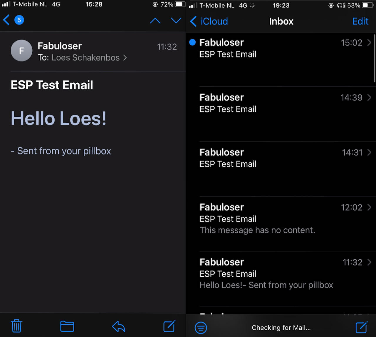
message.sender.name = "Fabuloser";
message.sender.email = AUTHOR_EMAIL;
message.subject = "Forgotten to take your pill today..";
message.addRecipient("Fabuloes", RECIPIENT_EMAIL);
/*Send HTML message*/
String htmlMsg = "<div style=\"color:#2f4468;\"><h1>Hi Fabuloser... you forgot some something this morning!</h1><p>- Sent from your pillbox</p></div>";
message.html.content = htmlMsg.c_str();
message.html.content = htmlMsg.c_str();
message.text.charSet = "us-ascii";
message.html.transfer_encoding = Content_Transfer_Encoding::enc_7bit;
Recieving this emails on my phone made me so happy :)
Initializing the LED and signals and ready to start the loop:
// initialize the leds as outputs
  pinMode(L1, OUTPUT);
  pinMode(L2, OUTPUT);
  pinMode(L3, OUTPUT);
  pinMode(L4, OUTPUT);
  pinMode(L5, OUTPUT);
  pinMode(L6, OUTPUT);
  pinMode(L7, OUTPUT);

  // initialize the reflection signals as an input:
  pinMode(S1, INPUT);
  pinMode(S2, INPUT);
  pinMode(S3, INPUT); //Pin 14 seems to also be used for WiFi interrupt
  pinMode(S4, INPUT);
  pinMode(S5, INPUT);
  pinMode(S6, INPUT);
  pinMode(S7, INPUT);


  //Starting sensor reset
  midnightReset();
}//setup
Here is the full loop, in words it does this:
- get time date from NTP server
- when it is 9 o’clock on a new day light up that day
- check constanly if the pill is in there, when out switch of LED
- after 3 hours check the signal, if the pill is still in there send an email and blink with the LED.
- at 12 midnight, reset and do the whole thing again.
//////////LOOP//////////
void loop() {
  //Update the current time
  getTime();
  //Check pil signals
  signals();

  //Check if its the next day, and if yes, reset
  midnightReset();

  delay(1000);
}//void loop

/////////// TIMEINFO //////////
// time synch and serial print
void getTime(){
  if(!getLocalTime(&timeinfo)){
    Serial.println("Failed to obtain time");
    return;
  }//failed to obtain time

  // Serial.print("Start hour: ");
  // Serial.println(timeinfo.tm_hour);
}//getTime

/////////////// RESET ///////////////
void midnightReset() {
  if(current_day != timeinfo.tm_wday) {
    //Reset variables
    email_send = false;
    pil_taken = false;
    current_day = timeinfo.tm_wday;

    //Set all LEDs to LOW
    digitalWrite (L1, LOW);
    digitalWrite (L2, LOW);
    digitalWrite (L3, LOW);
    digitalWrite (L4, LOW);
    digitalWrite (L5, LOW);
    digitalWrite (L6, LOW);
    digitalWrite (L7, LOW);
  }//if
}//midnightReset

///////////SIGNAL AND LED//////////
//signal read and led from box1
void signals(){

  if(timeinfo.tm_wday == 0) { //Sunday
    checkDay(0, L7, S7);
  } else if(timeinfo.tm_wday == 1) { //Monday
    checkDay(1, L1, S1);
  } else if(timeinfo.tm_wday == 2) { //Tuesday
    checkDay(2, L2, S2);
  } else if(timeinfo.tm_wday == 3) { //Wednesday
    checkDay(3, L3, S3);
  } else if(timeinfo.tm_wday == 4) { //Thursday
    checkDay(4, L4, S4);
  } else if(timeinfo.tm_wday == 5) { //Friday
    checkDay(5, L5, S5);
  }else if(timeinfo.tm_wday == 6) { //Saturday
    checkDay(6, L6, S6);
  }//else if


void checkDay(int w_day, int L, int S) {
  int SS;

  if(pil_taken == false) {
    Serial.print("Today is ");
    Serial.println(&timeinfo, "%A");

    //Check the correct sensor status
    //pil = inside -> HIGH, pil away -> LOW
    SS = digitalRead (S);

    if(timeinfo.tm_hour >= start_hour && timeinfo.tm_hour <= start_hour + check_hour) {
      digitalWrite (L, HIGH); //Turn LED on
      if(SS == 0) { //Pil is taken
        digitalWrite (L, LOW);
        Serial.print(&timeinfo, "%A");
        Serial.println(" pill taken");
        pil_taken = true;
      }//if
    }//if
    else if(timeinfo.tm_hour > start_hour + check_hour) { //Pil not taken at required time
      if(SS == 1 && email_send == false) {
        //Send an email
        Serial.println("going to send email");
        sendEmail();
        Serial.println("email send");
        email_send = true;
      }//if
      if(SS == 1) blink(L);
      if(SS == 0) { //Pil is taken
        digitalWrite (L, LOW);
        Serial.print(&timeinfo, "%A");
        Serial.println(" pill taken");
        pil_taken = true;
      }//if
    }//else if
  }//if pil not taken

}//checkDay

/////////////// BLINK LED ///////////////
void blink(int PIN_LED) {
  unsigned long currentMillis = millis();
  if (currentMillis - previousMillis >= interval) {
    // save the last time you blinked the LED
    previousMillis = currentMillis;

    // if the LED is off turn it on and vice-versa:
    if (ledState == LOW) ledState = HIGH;
    else ledState = LOW;

    // set the LED with the ledState of the variable:
    digitalWrite(PIN_LED, ledState);
  }//if
}//blink

///////////////// EMAIL /////////////////
void sendEmail() {
  /* Connect to server with the session config */
  if (!smtp.connect(&session))
    return;

  /* Start sending Email and close the session */
  if (!MailClient.sendMail(&smtp, &message)) {
    Serial.println("Error sending Email, " + smtp.errorReason());
  }//if
}//sendEmail

/* Callback function to get the Email sending status */
void smtpCallback(SMTP_Status status){
  /* Print the current status */
  Serial.println(status.info());

  /* Print the sending result */
  if (status.success()){
    Serial.println("----------------");
    Serial.printf("Message sent success: %d\n", status.completedCount());
    Serial.printf("Message sent failled: %d\n", status.failedCount());
    Serial.println("----------------\n");
    struct tm dt;

    for (size_t i = 0; i < smtp.sendingResult.size(); i++){
      /* Get the result item */
      SMTP_Result result = smtp.sendingResult.getItem(i);
      //localtime_r(&result.timesstamp, &dt);

      Serial.printf("Message No: %d\n", i + 1);
      Serial.printf("Status: %s\n", result.completed ? "success" : "failed");
      //Serial.printf("Date/Time: %d/%d/%d %d:%d:%d\n", dt.tm_year + 1900, dt.tm_mon + 1, dt.tm_mday, dt.tm_hour, dt.tm_min, dt.tm_sec);
      Serial.printf("Recipient: %s\n", result.recipients);
      Serial.printf("Subject: %s\n", result.subject);
    }
    Serial.println("----------------\n");
  }//if
}//smtpCallback
time managment
I couldnt make a planning on forehand simply because i only realized how much time it would take by the time we were in the last weeks. Henk really pushed us to think about our final project from day 01 so the very first drawings are coming from a mind with no idea on how to make it just a visual idea, during the process the design change to the technical demands. For example the bottom of the boxes go around the sensors and create a funnel on top for the pill. During week 11 when we studied input i realized i needed to step it up if i wanted my final project to work, whcih still gave me 8 weeks but with all the assignments it was hard to find time to spend on my final project. So i tried to use the weeks to try out small sections, like the sensors i used for networking and interface week. As for materials i was using only what was in the waag already, the last version of my wooden bottom palte is actually made from left over pieces of wood, why use new when you can recycle. My main time consumer were the actuall boxes, to print them takes time and i had to do a lot of trial and error.
 - I am using it everyday and it makes my life so much easier, really proud i could make this.

- it would have been better if all sizes of pills would have worked, if the pill is to small it will fall into the hole and the sensor will not be able to reflect.
- later i want to also create a user interface, like an app so that i could check when away from home if the pill is in there.