Week 11
Input devices
Group assignment Probe an input device(s)’s analog and digital signals
Individual assignment Measure something: add a sensor to a microcontroller board that you have designed and read it.
Group assignment
 - Probe an input device(s)’s analog and digital signals
 - understand how sensors work
 - lots of googling, mostly after the groupassignment
 - find out what sensor does what
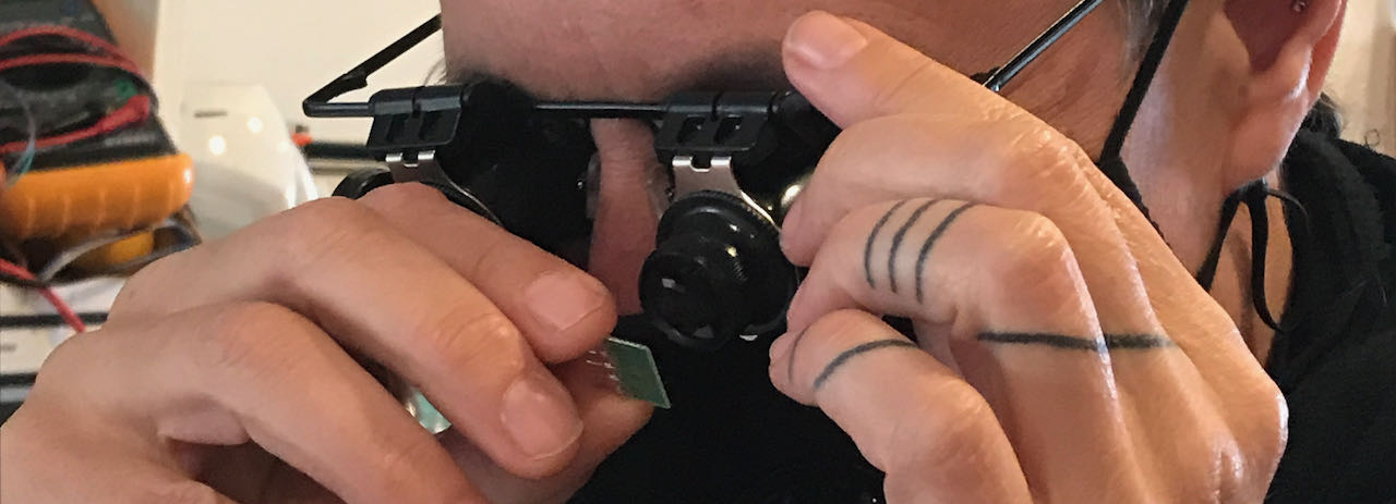
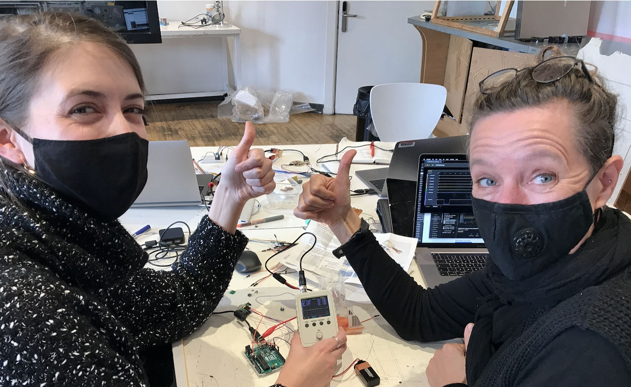
It was a bit of a hectic week at the lab in Amsterdam due to (thankfully false) negative corona test. So we had to figure out some things on our own, which ended being very beneficiary mostly because Nadieh had been learning from Henk how to use the logic analyser a few weeks before which helped us to get started. There are 2 basic tools that you use to debug and analyse which are the Logic Analyser and the Oscilloscope, both of them are in our electronic kit which some off us bought so tools enough, just a matter of learning how to use them.
The tools
Logic Analyser
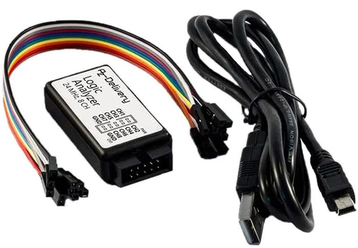
We started really simple mostly to understand how to work with the logic analyser, Nadieh was so friendly to help us figuring it out. In our kit we have an AZ Delivery logic analyser very basic, but it seems to work fine.
To use the Logic Analyser you have to install Logic2 from the Saleae website, which i already did 3 weeks ago when i was having trouble making my board with an ATtiny, a phototransistor, button and LED on it work but never learned how to use it. It turns out it’s pretty straight forward, the only thing you have to do is connect one wire to the ground and one wire to the line you wanna check, most of the time that would be one of the pins of your micro processor.
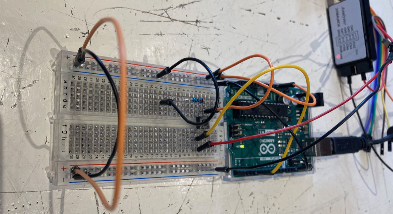
We tried a very simple button setup to figure out how to use the analyser.
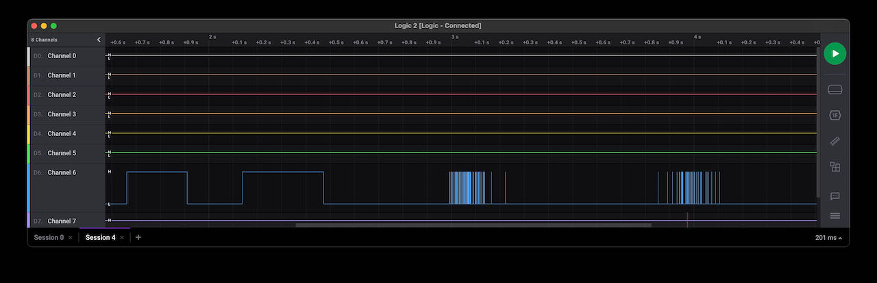
Now that i figured this out i tried my own board from some weeks ago and noticed i have a big de bounce on it as you can see on this logic screenshot.
Oscilloscope
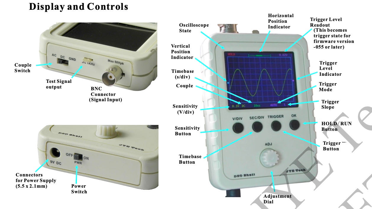
An oscilloscope is an electronic test instrument that graphically displays varying signal voltages, usually as a calibrated two-dimensional plot of one or more signals as a function of time. The displayed waveform can then be analyzed for properties such as amplitude, frequency, rise time, time interval, distortion, and other. Very handy instrument to figure out more exactly whats happening with your signal. In our kit is a KYE tech DSO Shell Oscilloscope for which we found online a detailed YouTube video
-
V/DIV: Select sensitivity or vertical position. The selected parameter indicator will be highlighted.
-
SEC/DIV: Select time base or horizontal position. The selected parameter indicator will be highlighted.
-
TRIGGER: Select trigger mode, trigger level, and trigger edge. The selected parameter indicator will be highlighted.
-
OK: Enter HOLD state (freeze waveform). Press it again will de-freeze.
-
ADJ: Adjust the parameter selected (highlighted).
-
Couple switch: Set couple to DC, AC, or GND. When GND is selected the scope input is isolated from input signal and connected to ground (0V input).
There is a pin on top which you can use for testing, which helped us at the beginning to figure out how to use it.
infra red movement sensor HC-ST501-PIR
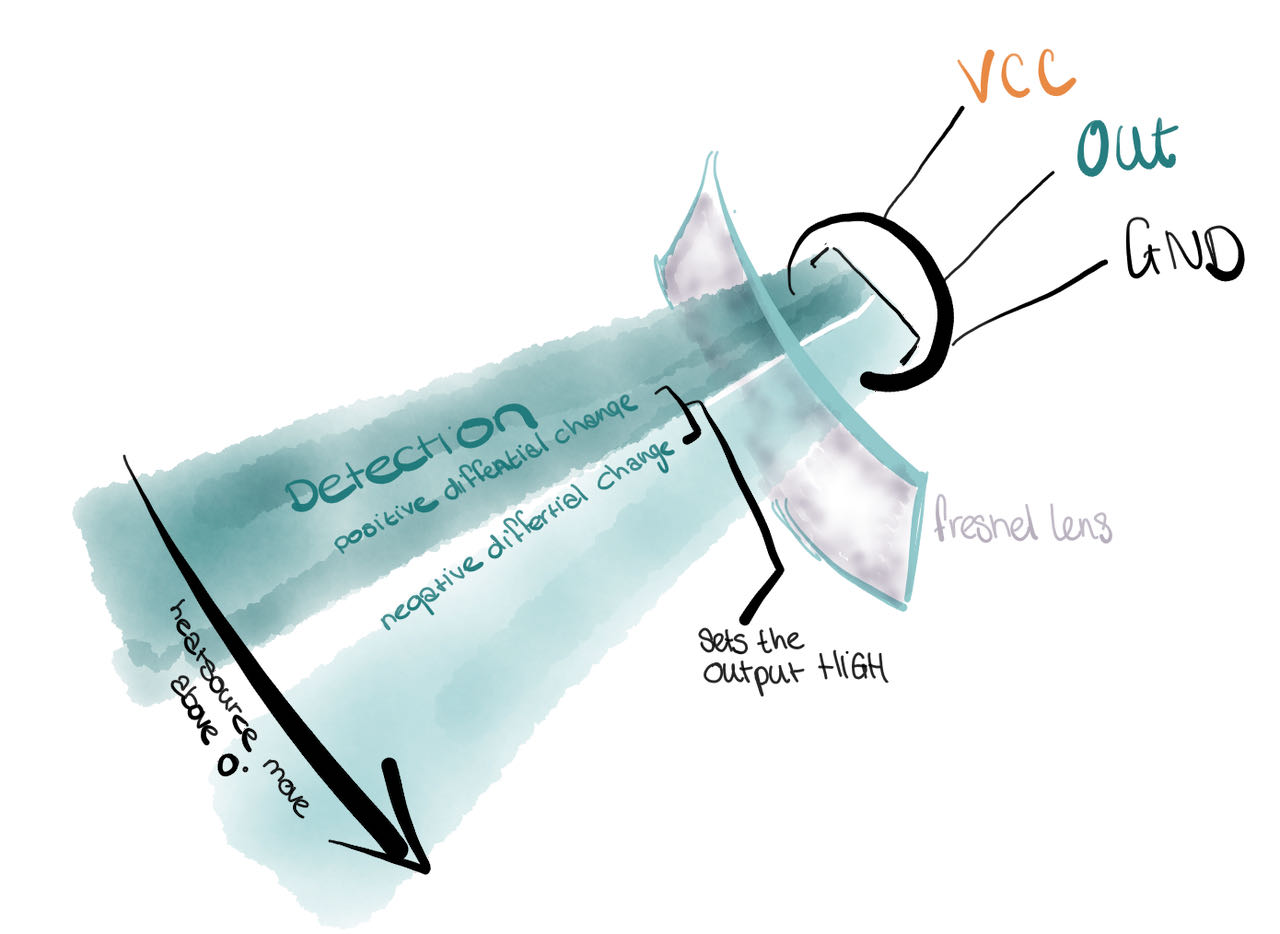
In the drawer of we found an infrared movement sensor HC-SR501-PIR which we connected to the breadboard, found some connection info and code online on this makersguide site When i was doing the documentation i also found this engineeringprojects site where its’s really well explained how it works.
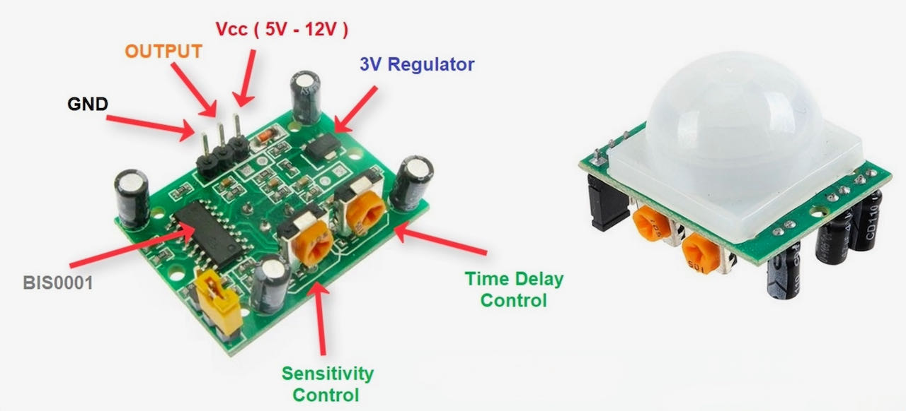
The pin out of the HC- SR501-PIR
- 1 - VCC (from 5v>12V)
- 2 - Signal out
- 3 - GND
The code we found on the makersguide site we copied into our Arduino IDE.
#define pin_PIR = 8
int value;

void setup() {
  Serial.begin(9600);
}//void setup

void loop() {
  value = digitalRead(pin_PIR); //read state of the PIR

  if (value == LOW) {
    Serial.println("No motion");
  } else {
    Serial.println("Motion!");
  }//else

  delay(500);
}//void loop
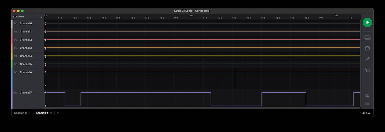
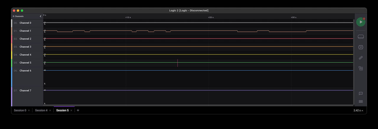
Strangely enough Nadieh her Logic Analyser didn’t seem to be working on her computer, when we moved the whole package to mine all of a sudden it worked, no logic :)
Nadieh her Logic Analyser on my computer
Light radar VL53L1X
Found some great explation on how light radar works on this makersportal site
Time of flight is based on Newtonian physics by assuming perfectly elastic contact with a surface. Most inexpensive ToF sensors use amplitude modulation to emit a singular or series of pulses at a particular frequency. For a laser, the frequency is usually in the infrared spectrum to ensure that the measurement is not visible to the human eye, and for an ultrasonic pulse its above the audible range. For an object at a distance x away from the light emitter (laser), we can approximate the reflection time for the light to hit the object and return back to the emitter. Which i tried to explain below:
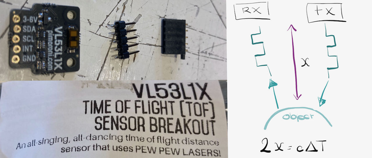
- x is the distance to the object (2x because the signal has to reflect back)
- c is the speed of the wave
- ΔT is the time it takes to travel 2x.
The width of the signal limits the minimum detectable signal. a pulse width within the nanosec range will be able to measure meters where as in the picosec range you can measure millimeters. The VL53L1X has a maximum range of 4m so probably used nanoseconds.
As always taking a picture with all the connections seen and no weird shadows is more difficult then it seems so i also put a schematic next to it this time.
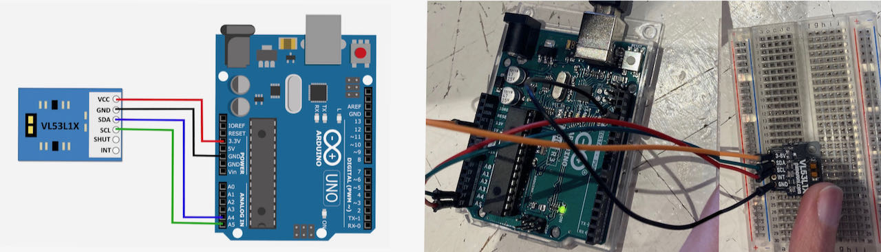
For the Light radar we had to install a library from this github site which you can see is referred to at the top of the code in the Arduino IDE.
#include <Wire.h>
#include <VL53L1X.h>

VL53L1X sensor;

void setup()
{
  Serial.begin(115200);
  Wire.begin();
  Wire.setClock(400000); // use 400 kHz I2C

  sensor.setTimeout(500);
  if (!sensor.init())
  {
    Serial.println("Failed to detect and initialize sensor!");
    while (1);
  }

  // Use long distance mode and allow up to 50000 us (50 ms) for a measurement.
  // You can change these settings to adjust the performance of the sensor, but
  // the minimum timing budget is 20 ms for short distance mode and 33 ms for
  // medium and long distance modes. See the VL53L1X datasheet for more
  // information on range and timing limits.
  sensor.setDistanceMode(VL53L1X::Long);
  sensor.setMeasurementTimingBudget(50000);

  // Start continuous readings at a rate of one measurement every 50 ms (the
  // inter-measurement period). This period should be at least as long as the
  // timing budget.
  sensor.startContinuous(50);
}

void loop()
{
  Serial.print(sensor.read());
  if (sensor.timeoutOccurred()) { Serial.print(" TIMEOUT"); }

  Serial.println();
}
The VL53L1X seems very accurate on a larger distance then 10cm although strangely enough it didn’t register the ceiling of the Waag which is for sure lower then 4m.
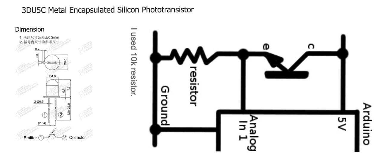
Phototransistor 3DU5C
On Henk his table was an unidentified object which i had mistaken to be an LED.. but some googling on images of photo transistors brought us to this datasheet which unmistakeably was our subject.
Some specifications:
The metal encapsulated silicon phototransistor is useful for building infrared sensors that can detect white or black. The operation of these sensors is based on the emission of IR light by an LED and its mirroring or absorption by white or black surfaces.
- Model: 3DU5C
- Material: Silicon tube
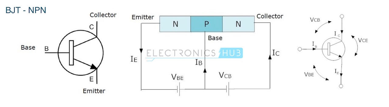
- Structure: NPN
- Maximum operating voltage: 10V;
- Current with closed transistor: 0 .3uA;
- Current with open transistor: 0.5mA - 1mA;
- Power: 30mW;
- Length of wave: 880nm (IR).
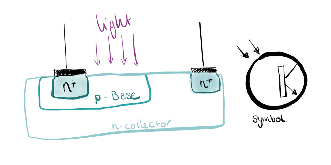
A phototransistor works just like a normal transistor, where the base current is multiplied to give the collector current, except that in a phototransistor, the base current is controlled by the amount of visible or infrared light where the device only needs 2 pins.
In the simple circuit the base current controlled by the amount of light will determine the collector current, which is the current going through the resistor (in our case 10 Ohm) Therefore, the voltage at Vout will move high and low based on the amount of light. We can connect this directly to an input of a micro controller.
The output of a phototransistor is dependent upon the wavelength of the incident light. These devices respond to light over a broad range of wavelengths from the near UV, through the visible, and into the near IR part of the spectrum. For a given light source illumination level, the output of a phototransistor is defined by the area of the exposed collector-base junction and the dc current gain of the transistor.
One of the main applications for photo transistors is object detection, could that work for my pill box?
We quickly found an Robotronics site with some instruction and code, very straightforward and easy to follow.
#define pin_Photo A0
int value;

void setup() {
  Serial.begin(9600);
}//void setup

void loop() {
  value = analogRead(pin_Photo);
  Serial.println(value);
  delay(10); // wait 10ms for next reading
}//void loop
It all seems so simple and straightforward but still wanted to know more so searched a bit on line and found this electronic notes site that explains how it works.
Photo transistor is a semiconductor and uses the basic bipolar transistor concept to operate. It works because light striking the semiconductor frees electrons / holes and causes current to flow in the base region.
Pro
- Have a relatively high gain and therefore they are relatively sensitive.
- Relatively cheap as they are effectively a transistor that is open to light.
- They can be incorporated into an integrated circuit.
- Offer a reasonable speed.
Con
- Cannot handle the high voltages of other semiconductor devices like photo-thyristors and triacs.
- In applications where they are exposed to transient voltage spikes and surges, they are open to damage
- Not as fast as other light sensitive electronic components like photo-diodes.
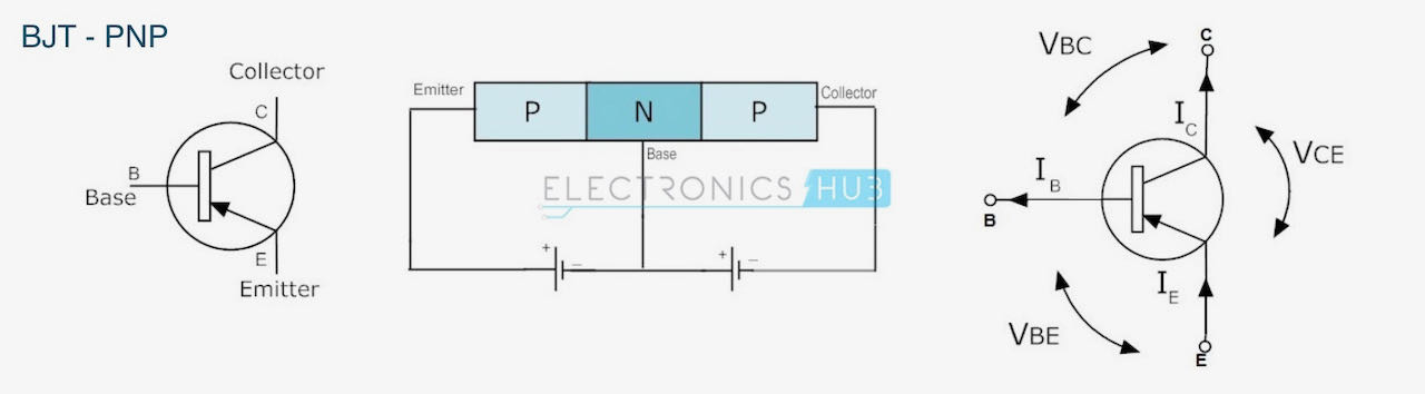
Phototransistors are classified into two types namely BJT and FET. The 3DU5C is BJT
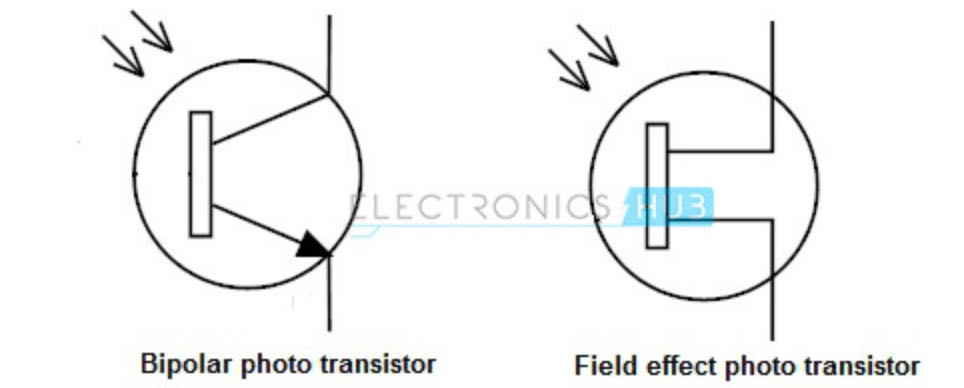
- BJT (bipolar junction) Phototransistor - Current controlled device, f small amount of current flows through the base of a BJT transistor then it causes to flow large current from emitter to collector. This distinguishes it from photo diode which cannot allow much current. The BJT transistors are only the transistors which are turned ON by the input current which is given to the base. Bipolar junction transistors can operate in three regions, they are:
- Cut-off Region: Here the transistor is in ‘OFF’ state i.e the current flowing through the transistor is zero.
- Active Region: Here the transistor acts as an amplifier.
- Saturation Region: Here the transistor is in fully ‘ON’ state and also works as a closed switch.
The BJT transistors are classified in to NPN and PNP transistors depending on the construction.
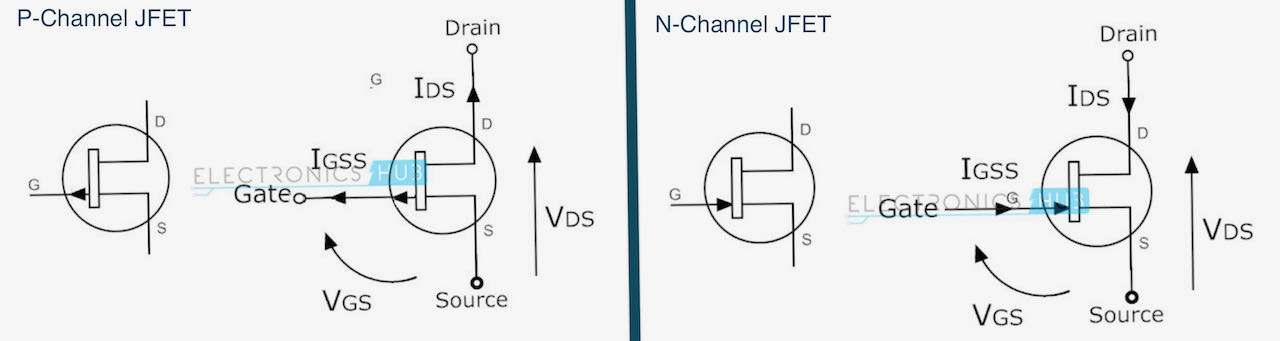
- FET (field effect) Phototransistor - This kind of phototransistor includes two terminals that connect inside through its collector & emitter otherwise source & drain within FET. The transistor’s base terminal reacts to light & controls the current flow among the terminals. Basically the FET transistors have three terminals they are
- Gate (G)
- Drain (D)
- Source (S).
The Junction-Field-Effect transistor (JFET) is an earliest and simple type of FET transistors. These JFETs are used as switches, amplifiers and resistors. This transistor is a voltage controlled device. It doesn’t need any biasing current. The voltage applied between gate and source controls the flow of electric current between source and drain of a transistor. The JFET transistors are available in both N-channel and P-channel types.
Sound Sensor Module micro for Arduino
Lucia was interested in the use of audio in sensors so we gave it a go and tried out a Arduino sound sensor module. The connection was very straight forward but appeartly it was not very sensitive .. took a lot of effort to get some input even though we really tried to be as precise as we could with the adjustable threshold. Here is theamazon site and this is the instruction & code we found here online
int ledPin=13;
int sensorPin=7;
boolean val =0;

void setup(){
  pinMode(ledPin, OUTPUT);
  pinMode(sensorPin, INPUT);
  Serial.begin (9600);
}

void loop (){
  val =digitalRead(sensorPin);
  Serial.println (val);
  // when the sensor detects a signal above the threshold value, LED flashes
  if (val==HIGH) {
    digitalWrite(ledPin, HIGH);
  }
  else {
    digitalWrite(ledPin, LOW);
  }
}
individual assignment
- Measure something: add a sensor to a microcontroller board that you have designed and read it.
- figure out which ones work for my final project
- research on the options with light reflecting
- have a clearer view on which sensor i can use
I have my mind set on making a board with a reflecting program and a hall sensor on it, which would just fit on an ATtiny412.
On the board will be close together an LED with a phototransitor and on the other side a hall sensor.
The way the LED/phototransistor can work is with Synchronous Detection, which i can explain a bit in words but better with the diagram below based on Neil his explanation. The curved line is the surrounding light and the cubic line the LED sending out pulses.
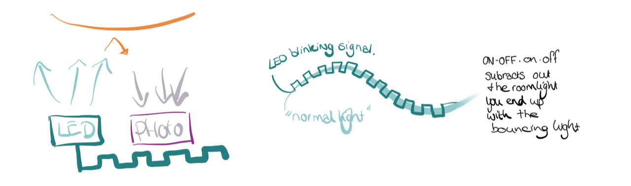
Synchronous Detection
In electronics, a synchronous detector is a device that recovers information from a modulated signal by mixing the signal with a replica of the un-modulated carrier. This can be locally generated at the receiver using a phase-locked loop or other techniques. Synchronous detection preserves any phase information originally present in the modulating signal. Synchronous detection is a necessary component of any analog color television receiver, where it allows recovery of the phase information that conveys hue.1 Synchronous detectors are also found in some shortwave radio receivers used for audio signals, where they provide better performance on signals that may be affected by fading. To recover base band signal the synchronous detection technique is used.
Hall effect
A Hall-effect sensor is a device to measure the magnitude of a magnetic field. Its output voltage is directly proportional to the magnetic field strength through it. Hall-effect sensors are used for proximity sensing, positioning, speed detection, and current sensing applications. Frequently, a Hall sensor is combined with threshold detection, so that it acts as and is called a switch.
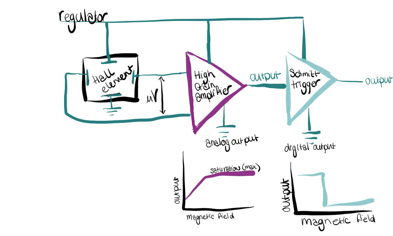
Analog version linear output, so you can also use the in between moments and use a treshold on in the curve where you want it.
Digital version basiscly switches between ON/OFF. would be curious if you can set the moment it switches ? Would that we in programming?
Soldering
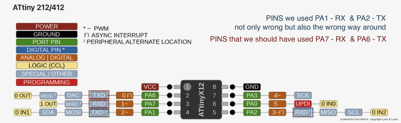
Before even starting I realized i never really understood the pins of the ATtiny so back to the drawingboard and while i am at i may as well swap the TX and the RX to their normal postions and not the ones we used last time so i dont have to use serial swap in my code.

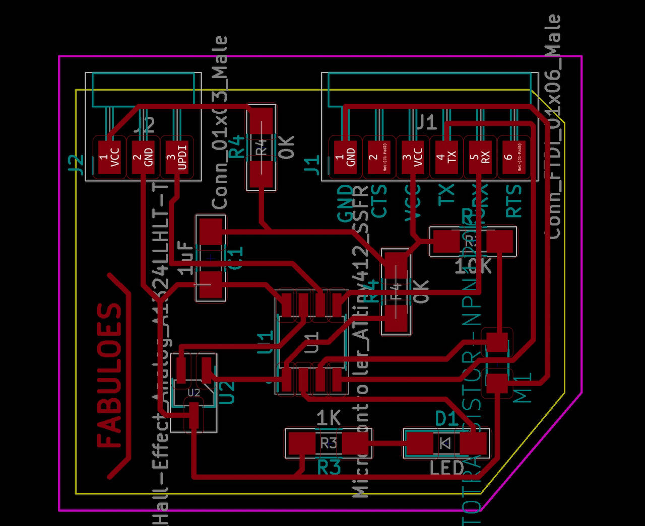
Here is the schematic, when i was blissfully unaware of the trouble ahead :)
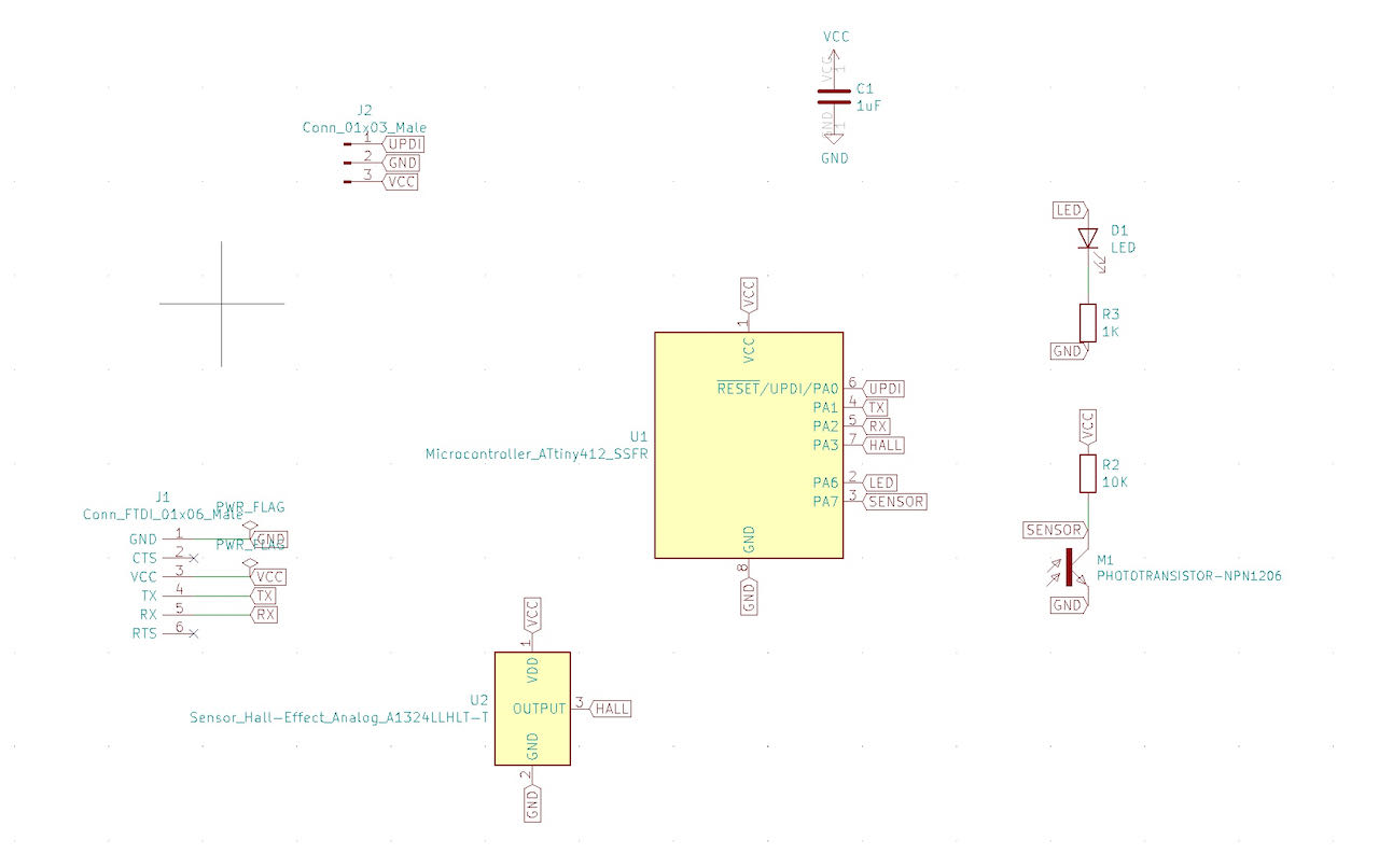
Ofcourse also put the board set up right to avoid traces issues.

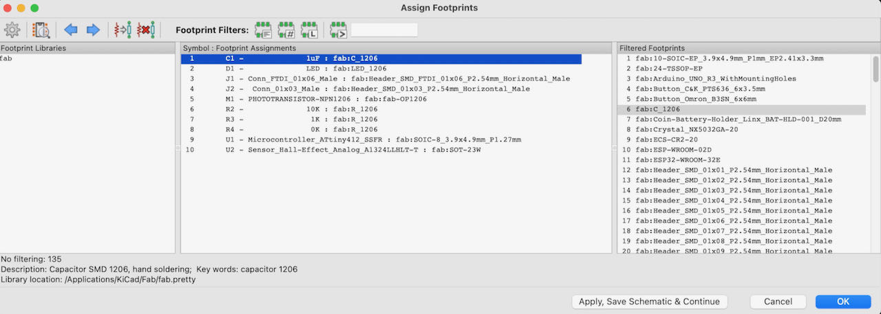
Had to dig up the Header footprint for the 3 pin header.

Which you can do with double clicking on the right one, don’t forget to apply, save schematic & continue before you click ok.
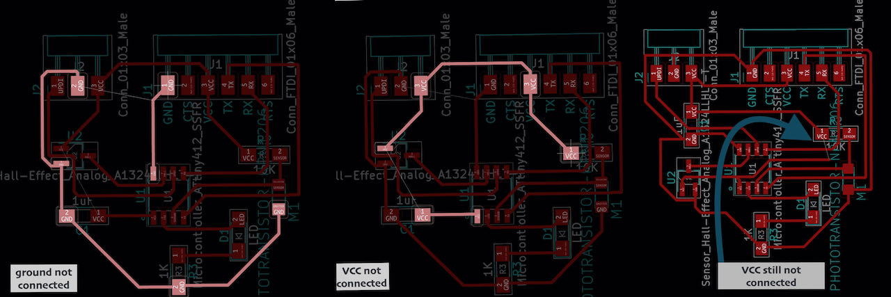
with update PCB from Schematic i got this beautiful ratsnest.

The untangling took a bit of time, even had to use a bridge from a 0R to connect the VCC.

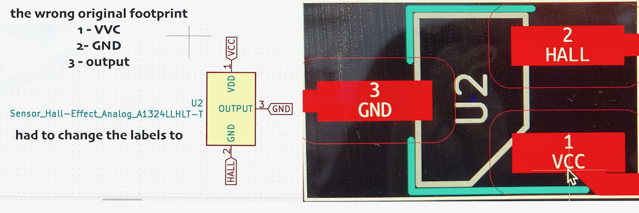
And just before i was exporting i got a txt in mattermost Hall pins are switched in Fab library... so happy that Nadieh warned me before i started milling. Took me a few minutes to change them around and reconnect the traces.
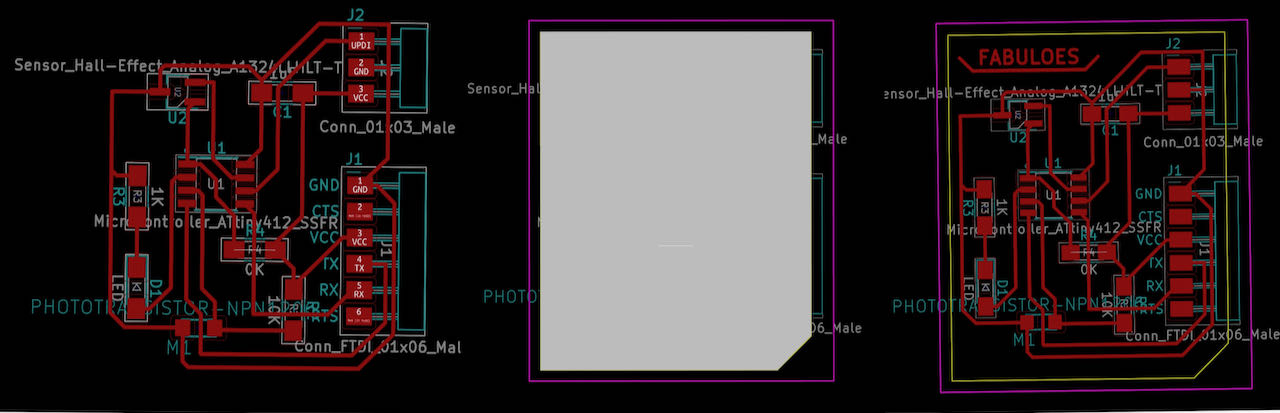
Finally the last steps:
- drawing an edge in the edge layer (yellow)
- creating a margin around the edges in the margin layer (magenta)
- and a new trick Nadieh taught me to draw a section in the DWG layer. (lightgrey)
When the mill was running i realized i was very lucky, tried to meaure out the size of the plate, it fitted just a bit bit less good as i thought.. i hear my coworker in my head “meten is weten” (measuring is knowledge).
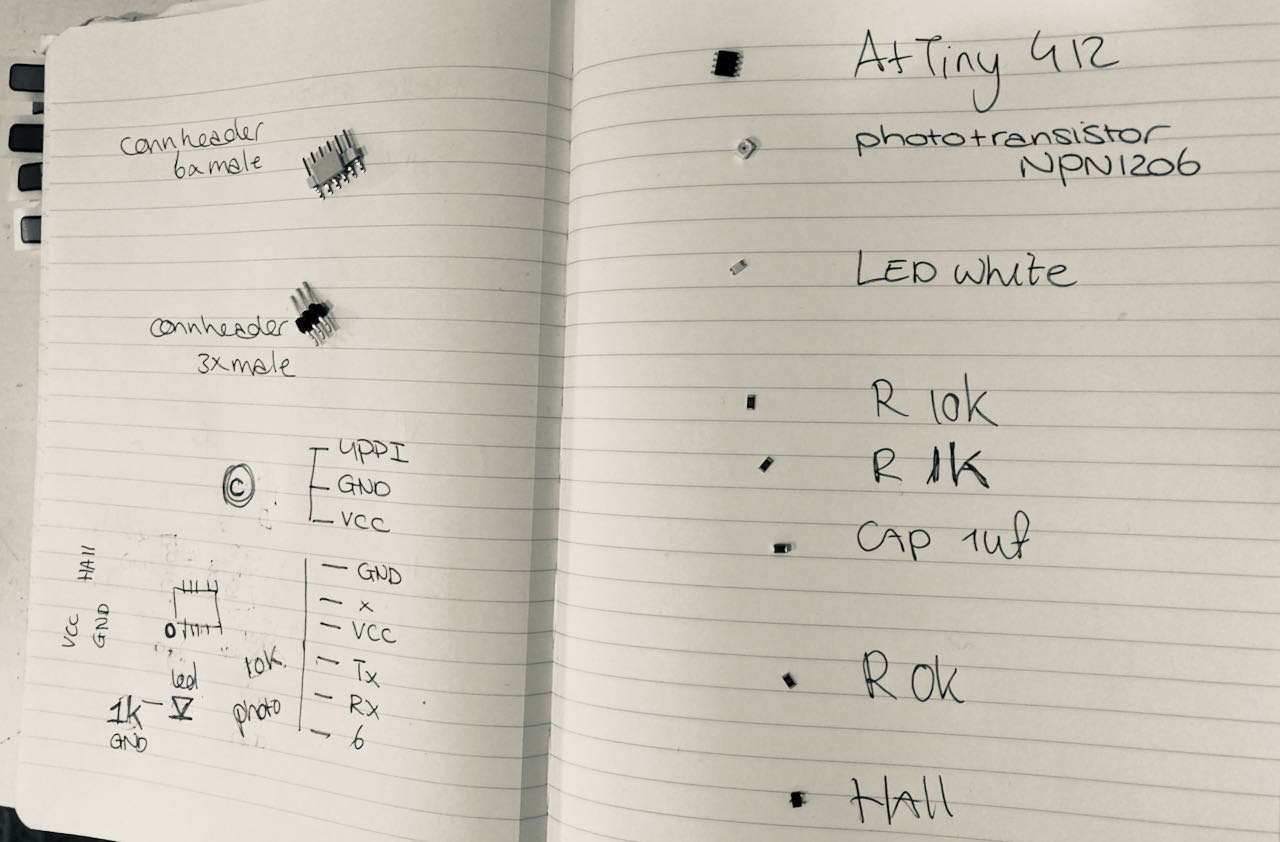
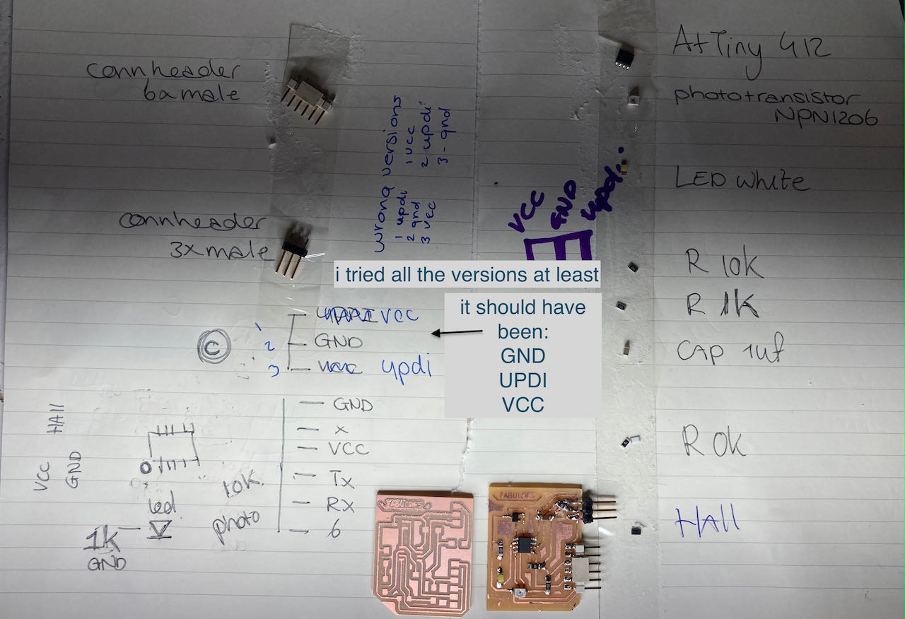
Got all my components together:
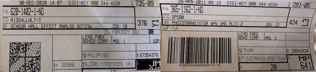
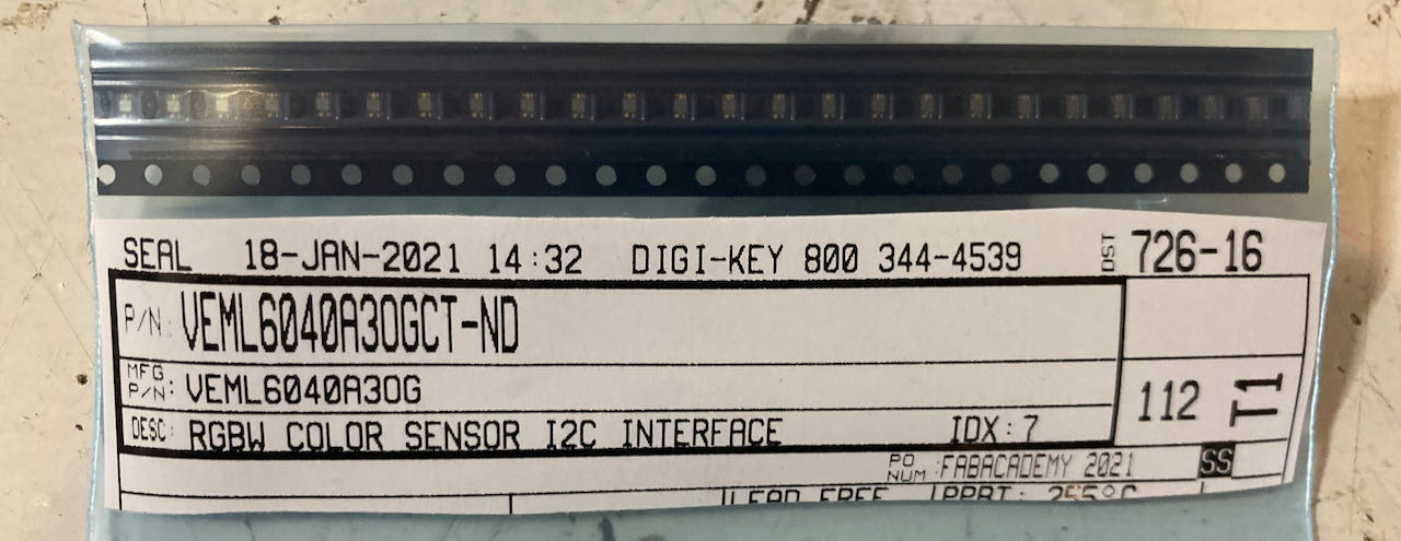
Just in case i need to look up specifications took pictures of the serial number of the Hall sensor and the phototransistor.
Back home i started soldering, first the VCC traces and the ATtiny so that i can check it.
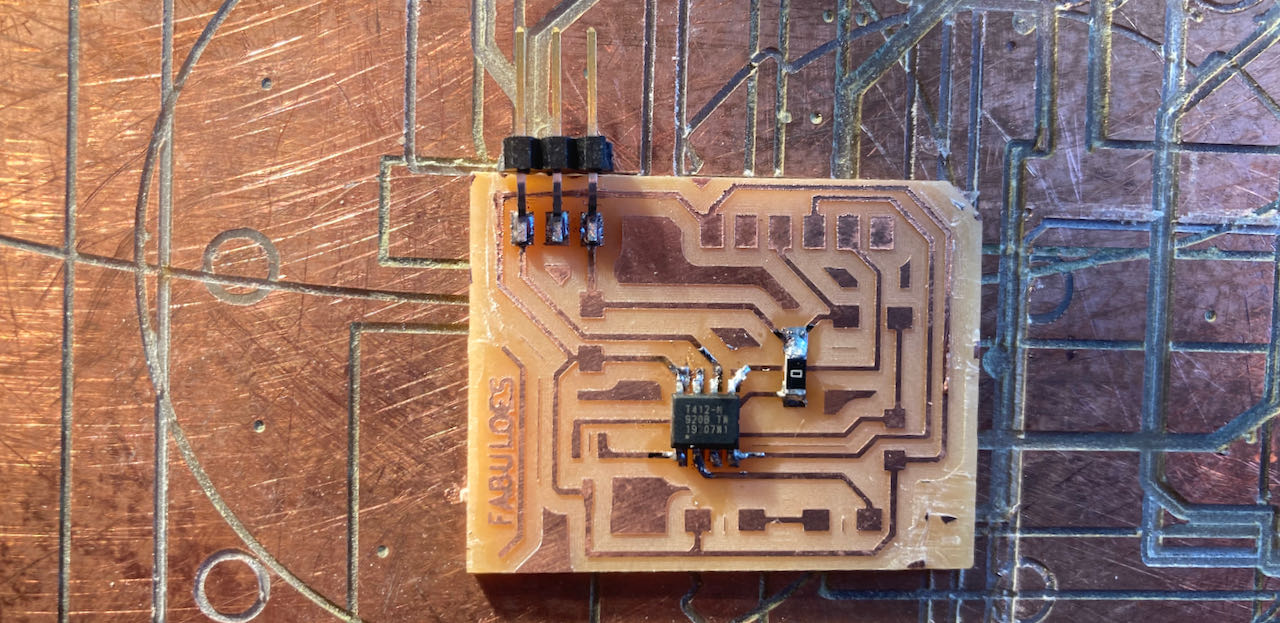
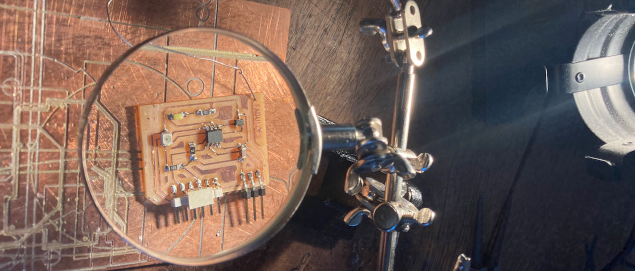
Continued with the rest, since my loop was not strong enough for my eyes to really see details i took pictures which showed me this big fail. There is a camera in my electronic kit, maybe time to unpack it.
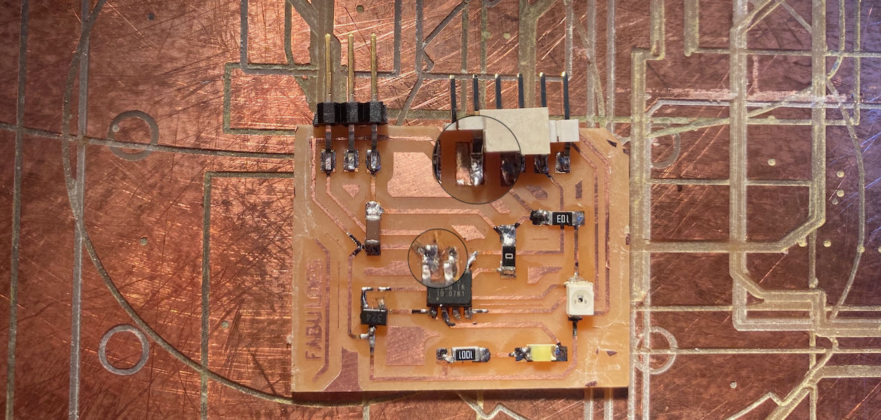
Look shiny and pretty before trouble started.
pin logic mistakes
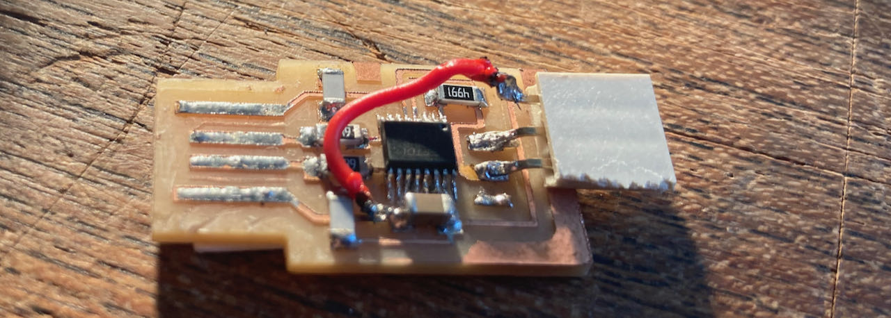
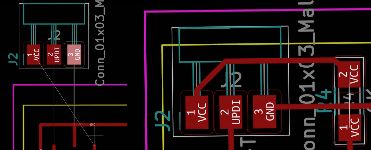
 I made an extra pin on my fpdi to be able to have VCC on the updi from the USB, so i don’t have to connect my FTDI for power. Maybe i should have not taken this turn in retrospective but now i have to deal with it. The original looked like this, with an extra wire on the 3rd pin to the VCC, but i realized it was wrong just not exactly how wrong..
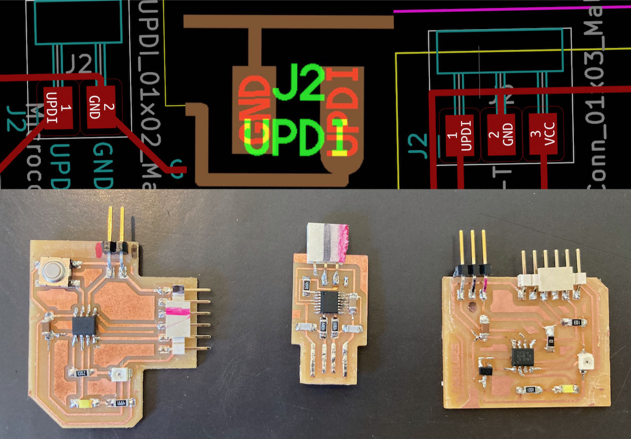
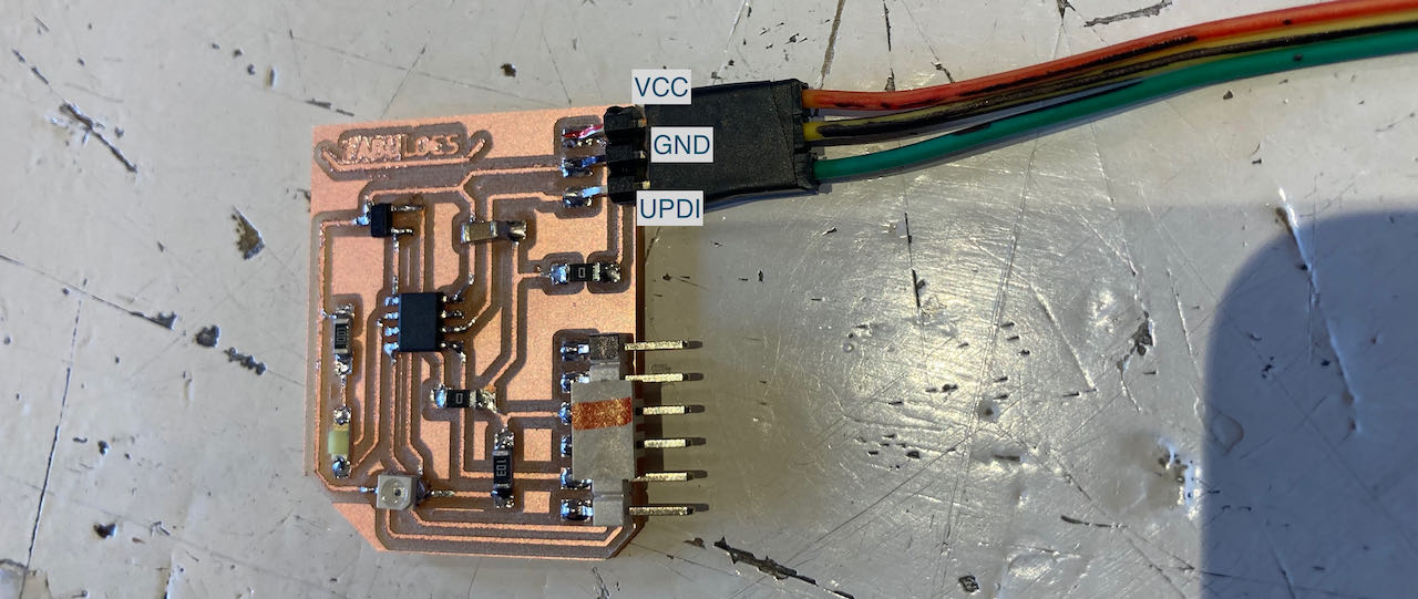
Another version of the Bypass as i was trying to get the pins right, but i am afraid i was able to blow up my UPDI with it.. not 100% sure yet but since time is running out i quickly made a overview for myself of the pin connections, also added the board i made before since i knew that one work with the FPDI before it had the bypass.
But with all the combination i kept on getting this error, the computer was not able to find the UPDI anymore.. the port was also not showing up in Arduino. by now if am really thinking i must have really connected it wrong and short circuited the board.

So decided to go to plan B, try to change the pin configuration on my new reflecting/Hall board.
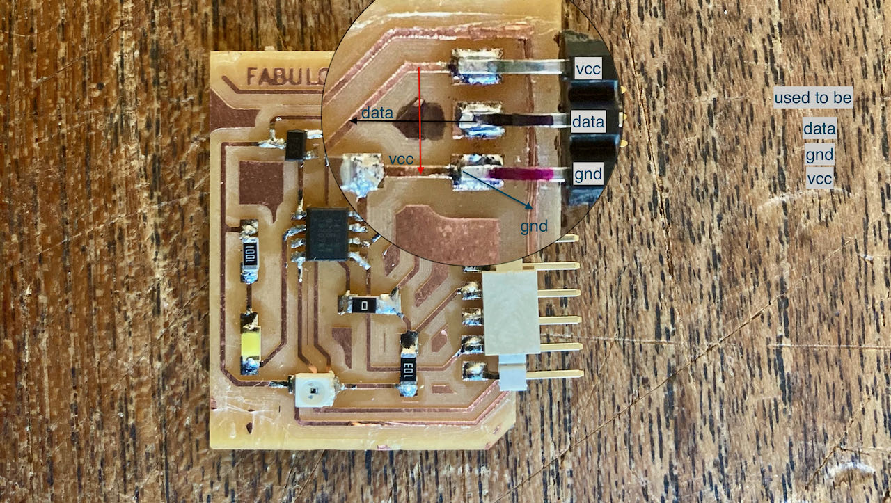
Took some scrapping and tapping of coppertape, but it seems to work according to the multimeter at least they are connected to the right pins on the ATTiny412.
Just in case i do get some milling time at the Waag tommorow i also changed it in the kicad file and exported it as a png, ready to mill. In retrospective i realize now that the pins are mirrored in this schematic..
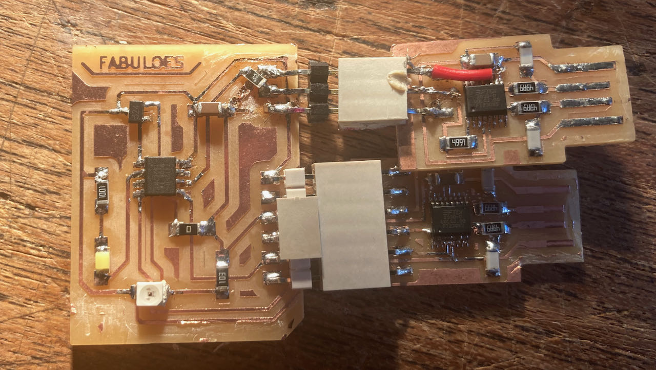
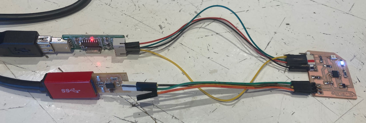
For now this is what i have.. an unreadable FPDI connected to the reflection hall board which i still have to program when i can reach it and am able to debug it.
If i still have time i want to mill this version of my board tomorrow with the right Hall sensor pins and the right (i hope) configuration of the FPDI pins, now that i was on it anyways i also made the gap a bit bigger between the headers, it was a bit cramped.
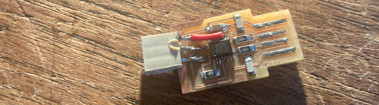
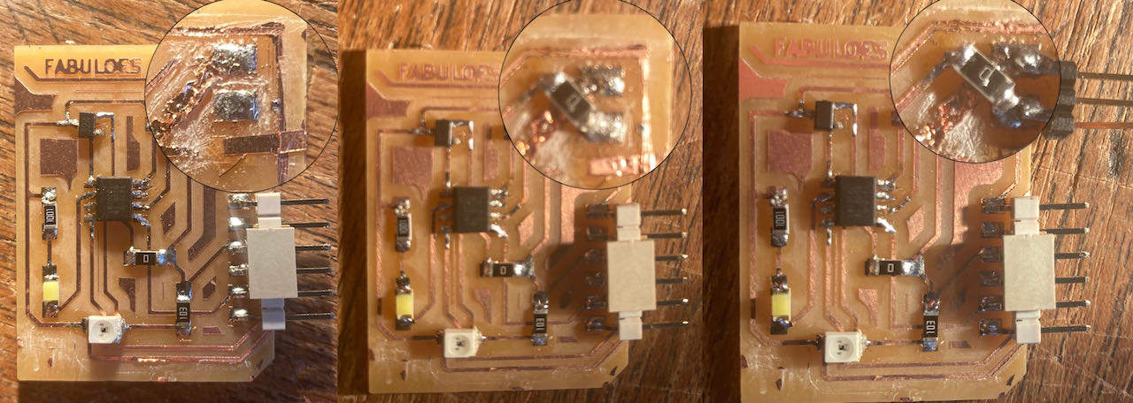
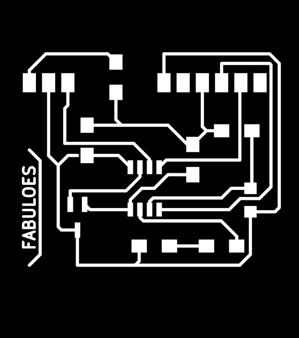
So i have to do another milling job, below are the traces and the layout. For the trained eye and people that understand you can see that again i messed up the pins for the UPDI…
After soldering i “fixed” the problem with wires in between the connections.
and the last and most stupid mistake with the pins i’ve made is not properly checking the RX and TX pins placement, so did swap them just not to the right place.. but strangely enough with using the serial.Swap(1); again it seems to work fine. Only checked the hello.code so far.
But when trying to get a serial reading it came out empty everytime..
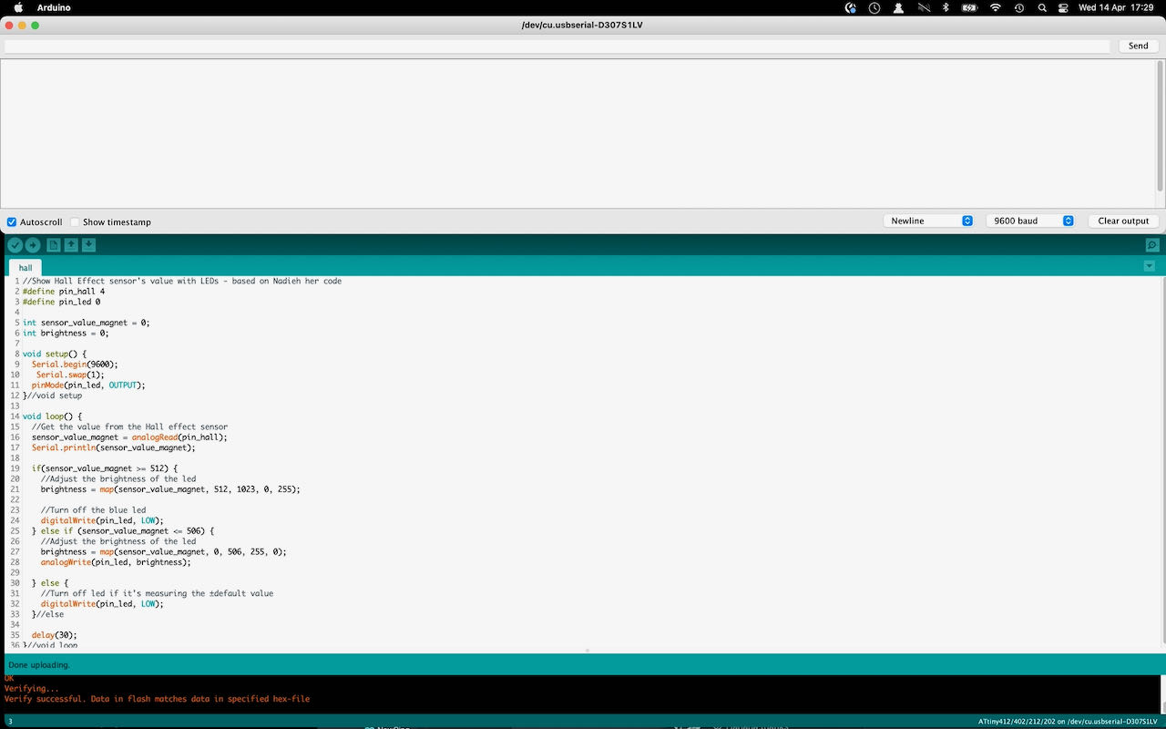
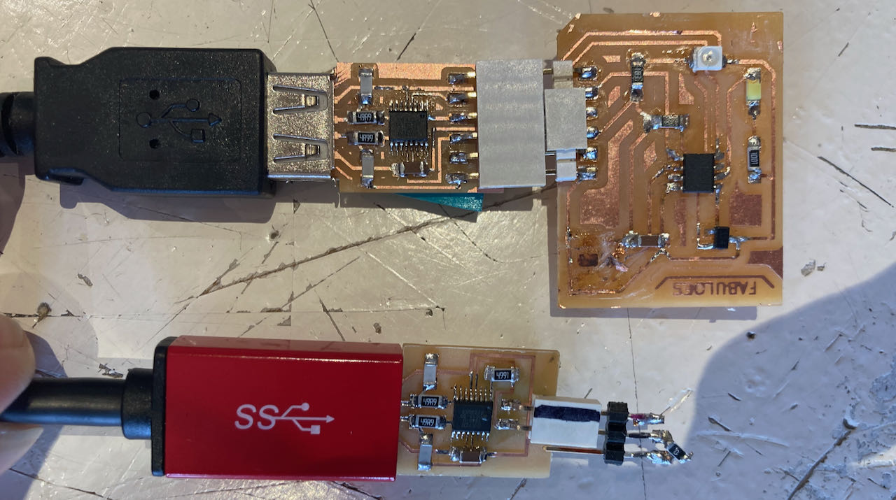
Even with this USB with a pin connection so that you can put the RX and TX where ever you need them, i guess literally swapping them has made it impossible to get any data out.
Luckily enough the code did seem to work, the LED reacted how it should to the Hall sensor and also the phototransistor. I made a few video to proof it :).
Hall sensor:
//Show Hall Effect sensor's value with LED - based on Nadieh her code

#define pin_hall 4
#define pin_led 0

int sensor_value_magnet = 0;
int brightness = 0;

void setup() {
  Serial.begin(9600);
   Serial.swap(1);
  pinMode(pin_led, OUTPUT);
}//void setup

void loop() {
  //Get the value from the Hall effect sensor
  sensor_value_magnet = analogRead(pin_hall);
  Serial.println(sensor_value_magnet);

  if(sensor_value_magnet >= 512) {
    //Adjust the brightness of the led
    brightness = map(sensor_value_magnet, 512, 1023, 0, 255);

    //Turn off the led
    digitalWrite(pin_led, LOW);
  } else if (sensor_value_magnet <= 506) {
    //Adjust the brightness of the led
    brightness = map(sensor_value_magnet, 0, 506, 255, 0);
    analogWrite(pin_led, brightness);

  } else {
    //Turn off led if it's measuring the ±default value
    digitalWrite(pin_led, LOW);
  }//else

  delay(30);
}//void loop
Phototransistor:
//Show Phototransistor value with LED - based on Nadieh her code

#define led_pin 0 // ATtiny PA6
#define photo_pin 1 //ATtiny PA7
int sensor_value = 0;
int output_value = 0;
int output_value_ease = 0;

void setup() {
  pinMode(led_pin, OUTPUT);
  pinMode(photo_pin, INPUT);
}//void setup

void loop() {
  // Read the analog value coming in from the phototransistor
  sensor_value = analogRead(photo_pin);
  //Map to 1 - 1000 and then ease that value
  output_value = map(sensor_value, 0, 1023, 1, 1000);
  output_value_ease = easeOut(output_value, 1.0, 1000.0);

  // Blink the LED with a 2*output_value_ease timing
  blinkLED(output_value_ease);
}//void loop

//t = current value, b = start value, d = end value
int easeOut(int t, float b, float d) {
  float n = (t - b) / (d - b);
  return(int)(d - b) * (1.0 - n*n*n*n) + b;
}// int easeOut

// Make the LED blink with a delay of delay_time
void blinkLED(int delay_time) {
  digitalWrite(led_pin, HIGH);
  delay(delay_time);
  digitalWrite(led_pin, LOW);
  delay(delay_time);
}// void blink
I am also very interested in this RGB sensor but suprise suprise i didn’t have time this week, on the todo list.
- a bit lost with all the pins, but learned a lot as the week was progressing, still unsure about some things bt hopefully the coming weeks will give some answers.
 - as i typed before..(will i ever learn?) research better before starting, time pressure seems to be the limitation every week.
- find time the coming weeks to mill a board with the right TX/RX and UPDI connection and read it out.