Week 09
Mechanical Design
Group assignment Design a machine that includes mechanism + actuation + automation. Build the mechanical parts and operate it manually. Document the group project.
Individual assignment Document your individual contribution.
Group assignment
 - Design a machine that includes mechanism + actuation + automation. Build the mechanical parts and operate it manually. Document the group project.
 - lights :) lets crack those those prefab lights
 - google for lots of ideas and later on for components
 - learn learn learn
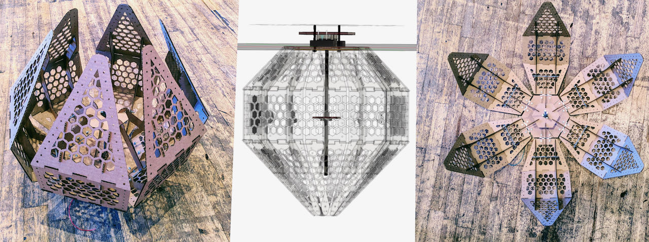
After Neil lecture our group stayed talking a bit longer and brainstormed a bit what could be a cool project to work on and fit within the assignment and soon we got on the track off folding and unfolding, Nicole found this inspiration of a Kinectic Smart Facade which triggered my brain towards StudioDrift. When we kept on talking and thinking, Nadieh found another flower this time an unfolding tulip. The idea was stuck in our brain.. how to makes this reality?

After a morning of brainstorming with Nicole guiding as through the process to make a beautiful nature inspired lamp which can fold in and out like a flower reacting to the amount of sunlight. Nadieh (the pedals and origami) and Nicole (the actual movement) already made it so far its impressive, Douwe is on top of the input department and i am in my comfortzone with the lights.
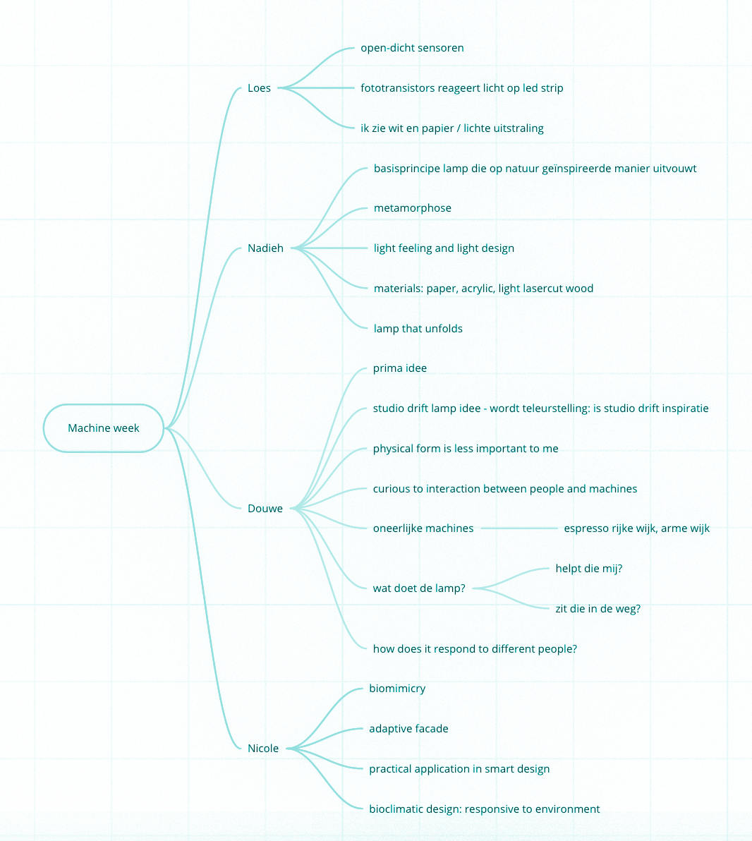
This diagram shows our individual views of what we were making, some comment are in dutch but you get the idea.
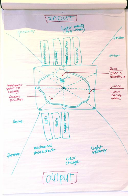
To be sure we were all on the same page and to understand all the in and outputs we drew it on a big board, during this process i personally realized i think differently about light, so it was very helpful to draw it out and put words on it. For instance for me the impact of a light can also be achieved with slight color changed between warm and cold not only with intensity.
With this in mind we started all our separate and yet connected roads to making flo glow. Nadieh and Nicole were very fast with creating a cardboard version which helped us all a lot visualize and for me specially to realize where and how to put create the lights.
individual assignment
- Design the lights to compliment the structure and movement
- lights :)
- do proper research for options before starting
- learning to crack some prefab systems
Not used but still great ideas:
Tungsten light dimmer
I really wanted to use a led bulb but it was so far impossible to find a good tutorial on line, seems very hard to do. So for now i will go with Tungsten to be able to fade at all, found a nice tungsten bulb light fade using TRIAC and Arduino projectsite
The first thing on the site is a warning that the circuit is connected directly to the mains AC voltage which of course scared me a bit but Henk is gonna help me to figure out a way to make it work, he already ordered the components for me (and i ordered a tungsten lightbulb).
I typed down some of the first thoughts that Henk shared while researching:
RGB LED strip WS2812B 5050 LED with RGB LED Strip Driver
This one we are probably not gonna use but it’s good for future reference. They belong to the Adafruit Neopixel family which is described below.
Led bulb RGB - ASTERA
I am using an Astera NYNX for my work and using a ready made CRMX (wireless DMX) sender but in the process of trying to find out if i could make my own, think at the moment it’s to much for me to oversee so slowly gathering information and learning.
To be able to send CRMX signal i would need one of these chips:
-
CRMX TIMO is fully compliant with the ETSI EN 300328 (v1.8.1) ‘2015’ revision, as well as fully FCC certified with a modular approval to 300mW – the highest allowed output power of any manufacturer within the industry due to LumenRadios unique CRMX technology.
-
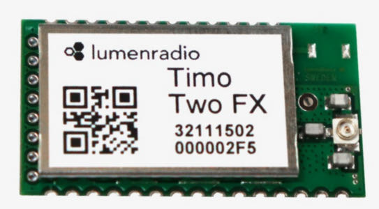
TIMOTWO is a fully integrated DMX/RDM module and offers over-the-air firmware upgrades, SMT mounting and a UF.L connector for external antennas.
Since the TimoTwo also has Bluetooth options i decided to order it but not sure if it will arrive in time, maybe for the wild card week?
TiMoTwo and Arduino link
TimoTwo and Github link
Usefull ideas for this project:
The options that could work are now narrowed down to 2 components first one:
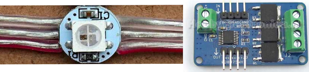
Led modules with drivers integrated - NEOPIXELS
I ordered a couple of led modules with drivers Neopixels to be more exact so that if the lightbulb doesn’t fit into the design i would have some alternatives. They seem very user friendly and with a nice online documentation on how to use the Neopixel library. Which ended up being the right choose since the bulb doesn’t really fit within the structure plus using a tungsten light within a paper structure sounds like asking for trouble.
Before i start googling its good to know that not all addressable LEDs are NeoPixels. “NeoPixel” is Adafruit’s brand for individually-addressable RGB color pixels and strips based on the WS2812, WS2811 and SK6812 LED/drivers, using a single-wire control protocol.
Practical limits of the Neopixels:
RAM:
NeoPixels require some RAM from the host micro controller; more pixels = more RAM. It’s only a few bytes each, but as most micro controllers are pretty resource-constrained, this becomes a very real consideration for large projects.
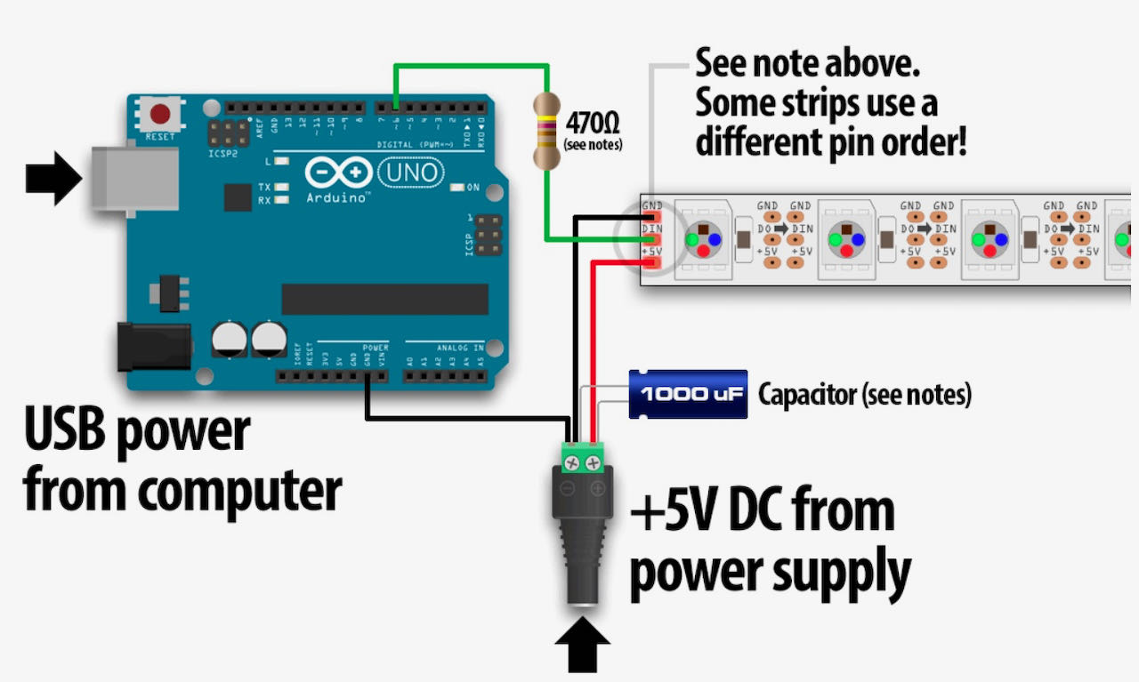
Power
- 5V DC power supply or a 3.7 Volt lithium-polymer battery.
- Each NeoPixel can draw up to 60 milliamps at full brightness
- When using a DC power supply use a large capacitor (1000 µF, 6.3V or higher) across the + and – terminals. This prevents the initial onrush of current from damaging the pixels. The capacitor buffers sudden changes in the current drawn by the strip.
- If powering the pixels with a separate supply, apply power to the pixels before applying power to the micro controller.
- Adding a ~470 ohm resistor between your micro controller’s data pin and the data input on the NeoPixels can help prevent spikes on the data line that can damage your first pixel. Neopixel rings already have one on there.
- Maximum of 2m of distance between the micro controller and the first pixel.
3.3V signal from the micro controller may not be “loud” enough to register with the higher-voltage device.
There are two ways this can be addressed:
- Lower the voltage to the NeoPixels so it’s closer (or equal) to that of the micro controller.
- Use a logic level shifter to step up the signal from the micro controller to the first pixel. This transforms 3.3V tot 5V and visa versa.
Luckily enough i don’t have to worry about this since we are using a separate power supply of 5V for the Neopixels.
I will use the safest way to calculate the current they use, there is a lot of debate online on how much it is exactly, figured better safe then sorry so 24 NeoPixels × 60 mA ÷ 1,000 = 1.44 Amps or the bigger ring 60 NeoPixels × 60 mA ÷ 1,000 = 3.6 Amps
Thus the power for our 60 Neopixels will be DC 5V/3.6Amps.
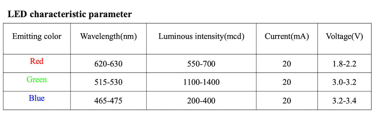
Same data of the individual leds i found in the datasheet:
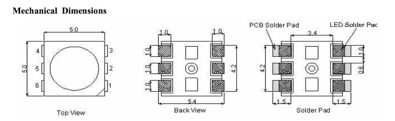
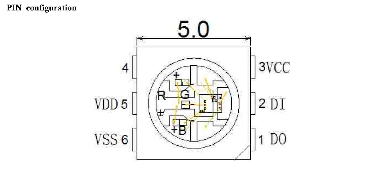
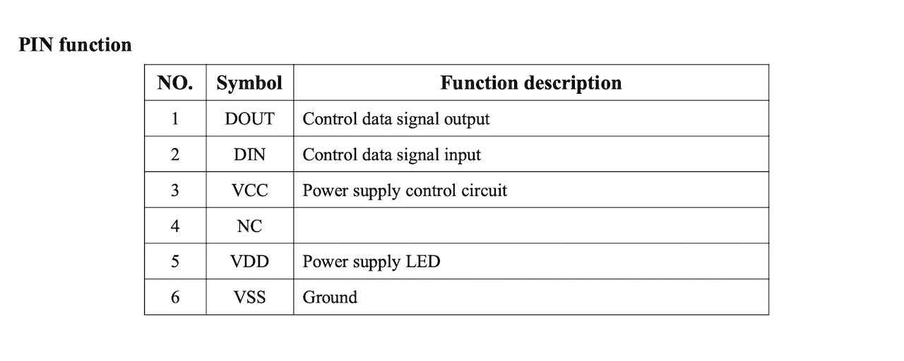
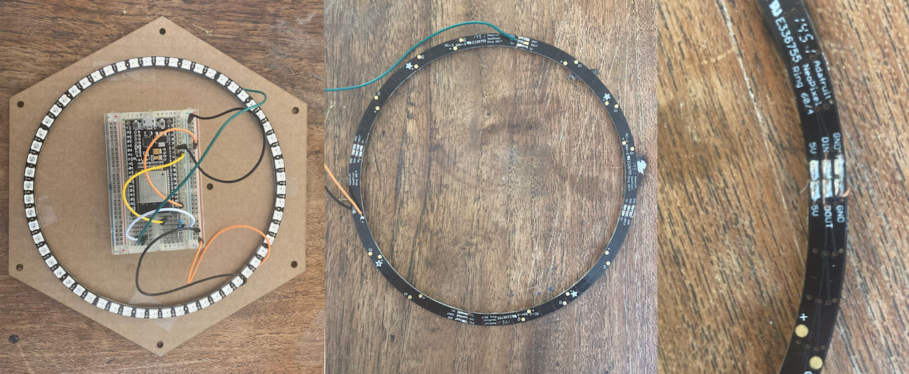
WS2812 5050 RGB LED Ring 24 & WS2812 5050 RGB LED Ring 61
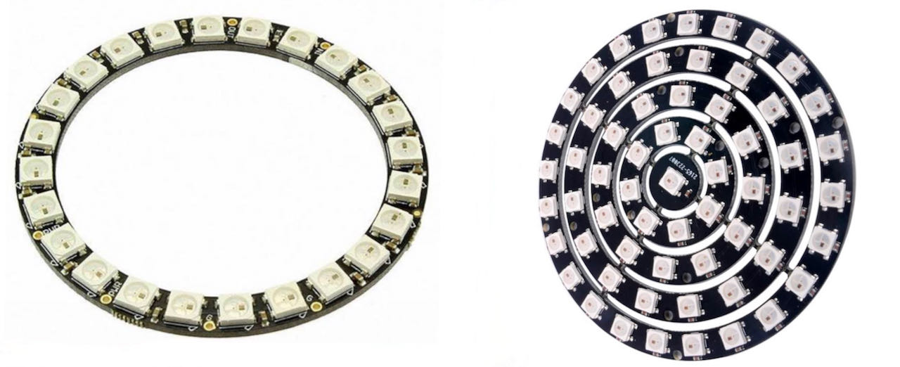
On the right the 24 ring and on the left the 16 circle of the full circle.
The 12 circle of the full circle.
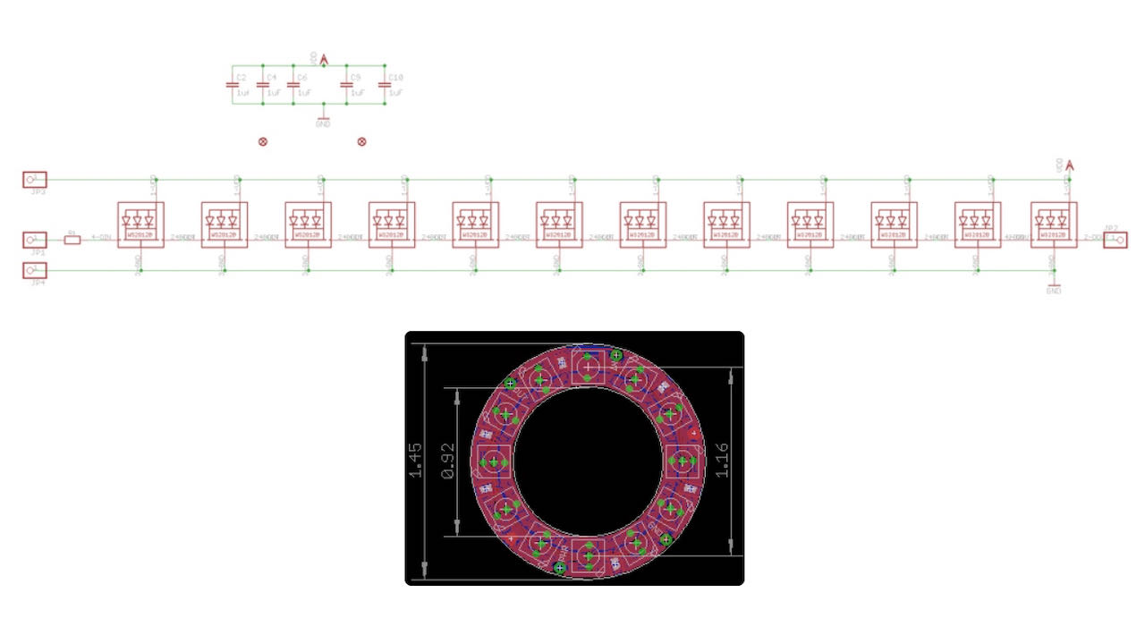
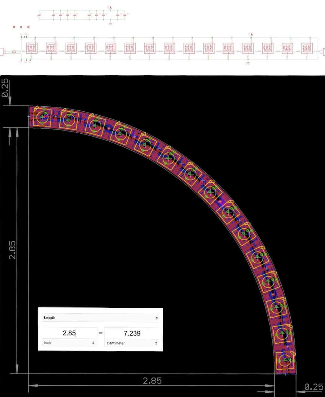
I also wanted a “big” circle so decided to go for it and order 4 of the 1/4 circle.
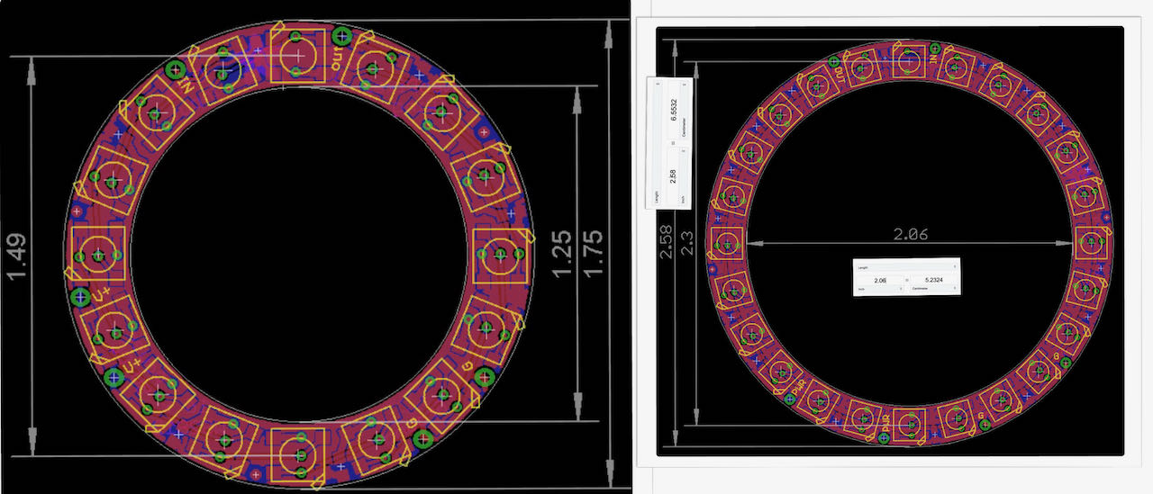
Some data on the NeoPixel 1/4 60 Ring - 5050
- Outer Diameter of Full Circle (four put together): 157mm
- Inner Diameter of Full Circle (four put together): 145mm
- Width of individual section: 6.4mm/0.25"
- Height: 2mm
When connecting put all the GND and 5V together and only 3 of the 4 D IN to D OUT, the remaining D IN in de input for the entire ring.
Controlling the Neopixels
There is a lot of information out there on how to control these LED module with an Arduino, for example this one but since we wanna fit all the code onto an ESP32 i need to find the right information on that. Fairly quickly bumbed into this tutorial from Instructables Circuits which ticks all the boxes (well close enough). Important note is that the library of Neopixels is not supporting any AVR microcontrollers, so no ATTiny this week.
- using an ESP8266 (in our case a ESP32)
- WS28112 Led ring
- Arduino IDE
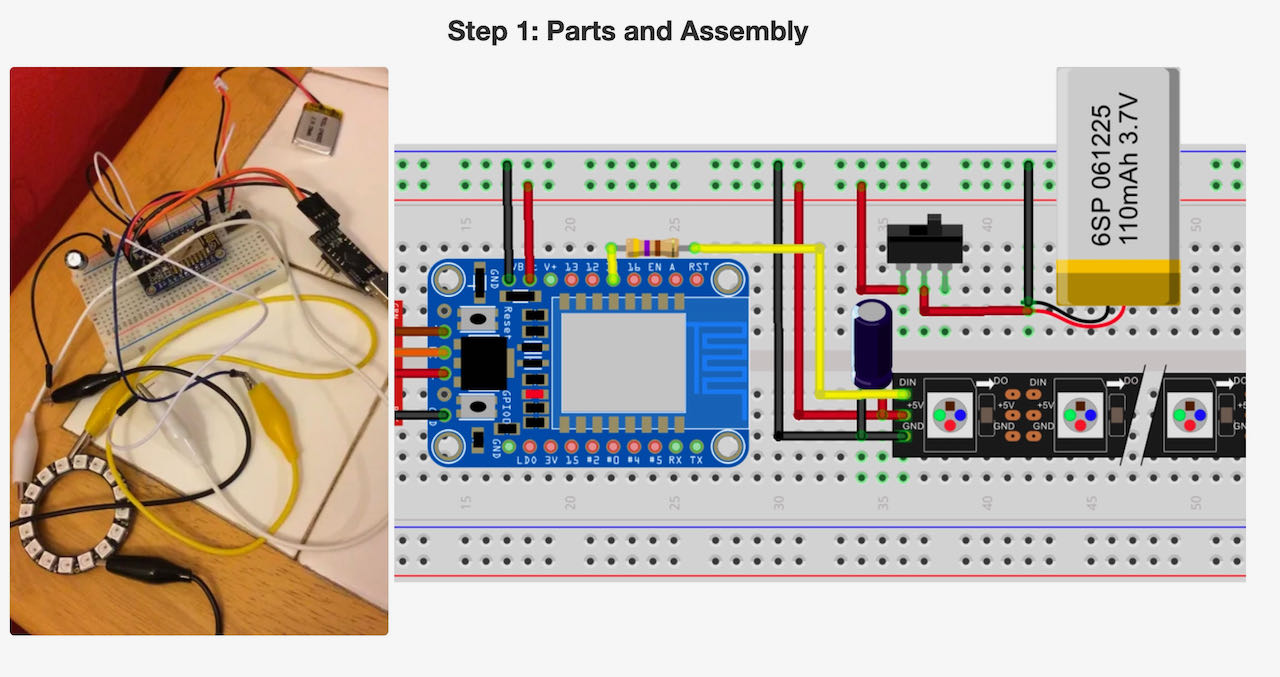
Thing i will need:
- ESP32
- USB cable
- 5V DV Power
- Capacitor to protect the Neopixels - 1000 uF
- 470ohm resistor
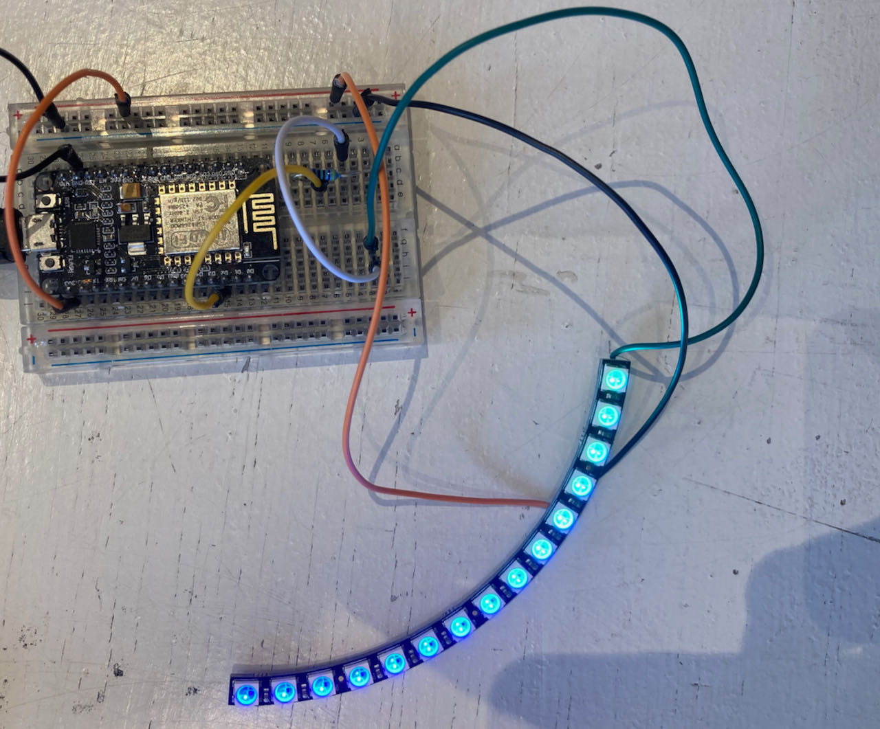
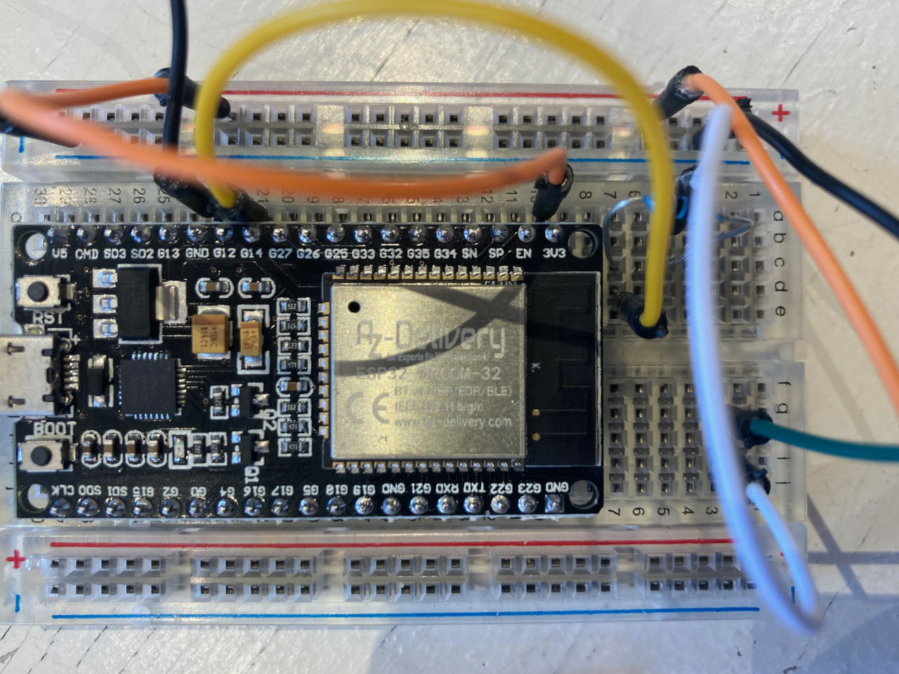
Made a small setup using a breadboard and a ESP8266 first to make sure i understood what i was doing, even went back to just making a single led blink and eventually 1/4 of the led ring.
 During this process i got an pyserial error as i also got a week ago, went to this Arduino Forum Site and followed the instructions again.. probably with all the reinstalling etc last week i must have recreated this problem.
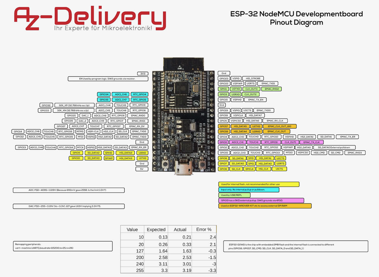
After making sure that worked and i understood i continued to change the board for an ESP32 and downloaded the Pinout Diagram.
Soldering the Neopixel ring, i started out with wire making a connection with the point but not only did it look ugly i was hard to make the pieces really connect so i ended up using a tiny copper wire and put this in the solderbridge, first a bit of a struggle but slowly got the hang of it till Henk had to kick me out of the Waag. Later on i found a great tutorial which could maybe help other but i would suggest to put a tiny bit of wire in it.
To work with the Neopixel i had to install the AdaFruit Pixel Library which i found here
Found a funny site which is called LedstripsEffectsGenerator and it does exactly that but not only would that result in me never learning code it also seems like the code is a bit overcomplicated (big file 275K for a simple task) and not so easy to read, which makes sense with it being a generator.
Ofcourse there is this great strandtest with the explampels which showed me the possibilities, now i wanna learn how to do this myself.
Some of the experiments but still a lot of programming to do:
- pretending to be a sunset
- blinking for attention
some bonus info:
El Wire
EL wire is capacitive, and cannot be PWM’ed or easily dimmed which makes this process harder to achieve. Electroluminescent wire is not easily adjusted in brightness, therefore fading in and out is hard. Two main techniques are used to change the brightness of the electroluminescent wire, one is based on a custom build driver that actually shifts electroluminescent wire brightness by changing the alternating current frequency.
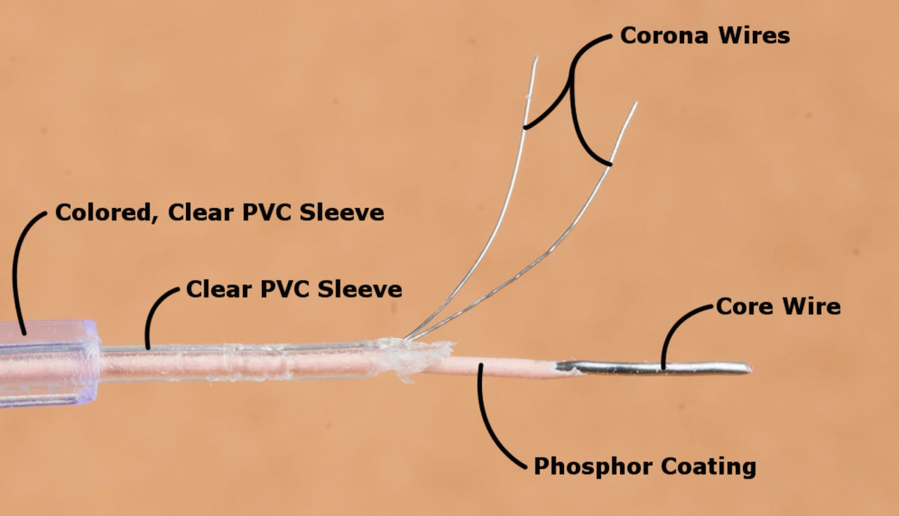
EL wire production starts with a solid copper core, which acts as a conductor. A conductor is a material through which electricity - a flow of electrons - moves easily. The entire copper core is covered with an even layer of phosphor lubricant. Phosphorus - like the kind in light sticks and other glow-in-the-dark products - is the key to electroluminescent wire. Phosphorus is a solid material that gives off light when exposed to an energy source, such as electricity.
Then two very thin copper wires are tied together into a long wire. This wire is coiled around the phosphor coated copper core. You now have a layered unity. Think of its core as a sandwich - two conductors with electricity flowing through it provide the energy needed to light up the phosphor.
EL wire can break if exposed to moisture. This is where the two PVC sleeves come into play. These sleeves protect the EL wire from the elements - this is especially important when using EL wire outdoors - and give it its flexibility. The first PVC sleeve, which is quite thin and lightweight, is pulled over the entire guide unit. This inner cover is made of a clear, waterproof plastic. The second PVC sleeve, which is often chemically dyed to produce a wide variety of colors, is laid all over the strand. It provides an extra layer of protection and is often variegated to give the illusion of texture.
In order for EL wire to glow continuously, it needs a constant supply of electric current. With alternating current (AC), the electric current moves back and forth between the positive and negative terminals of the circuit. This alternating polarity means that electricity is constantly flowing through the circuit, giving the EL wire a constant supply of current. As a result, the phosphorus atoms are continuously ionized or their electrons have a different energy level. Since these ions always jump their electrons from one energy level to another - the process by which they emit light - they will glow continuously. In addition, AC can deliver higher voltages than DC, because alternating current can be turned up or down by using transformers. This is key to determining how bright your EL wire will shine. Higher voltages cause more electron excitation, which in turn leads to brighter light.
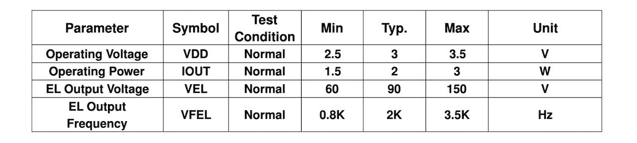
Power
- each meter draws about 10-15mA at high voltage
- El wire is sort af a capacitor.
- The voltage should be between 50-120V AC RMS (root mean square) (150V-360V peak-to-peak). Higher voltages result in a brighter display (but lower overall wire-life)
- The AC frequency can run from 60Hz to 2000Hz, higher frequency results in a brighter display (but lower overall wire-life).
15mA per meter will give us 90mA for our 6m setup
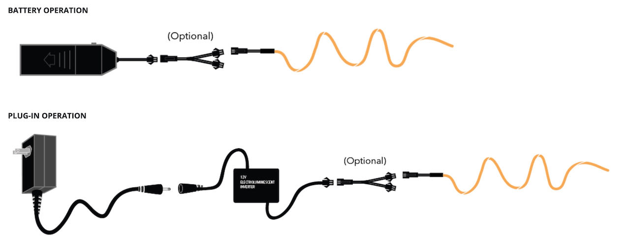
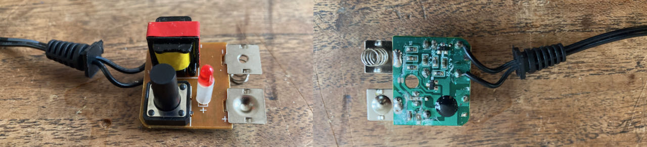
EL wire inverter
The inverter sends a specific voltage and frequency throughout the panel which excites the phosphor particles inside the wire creating the glow.
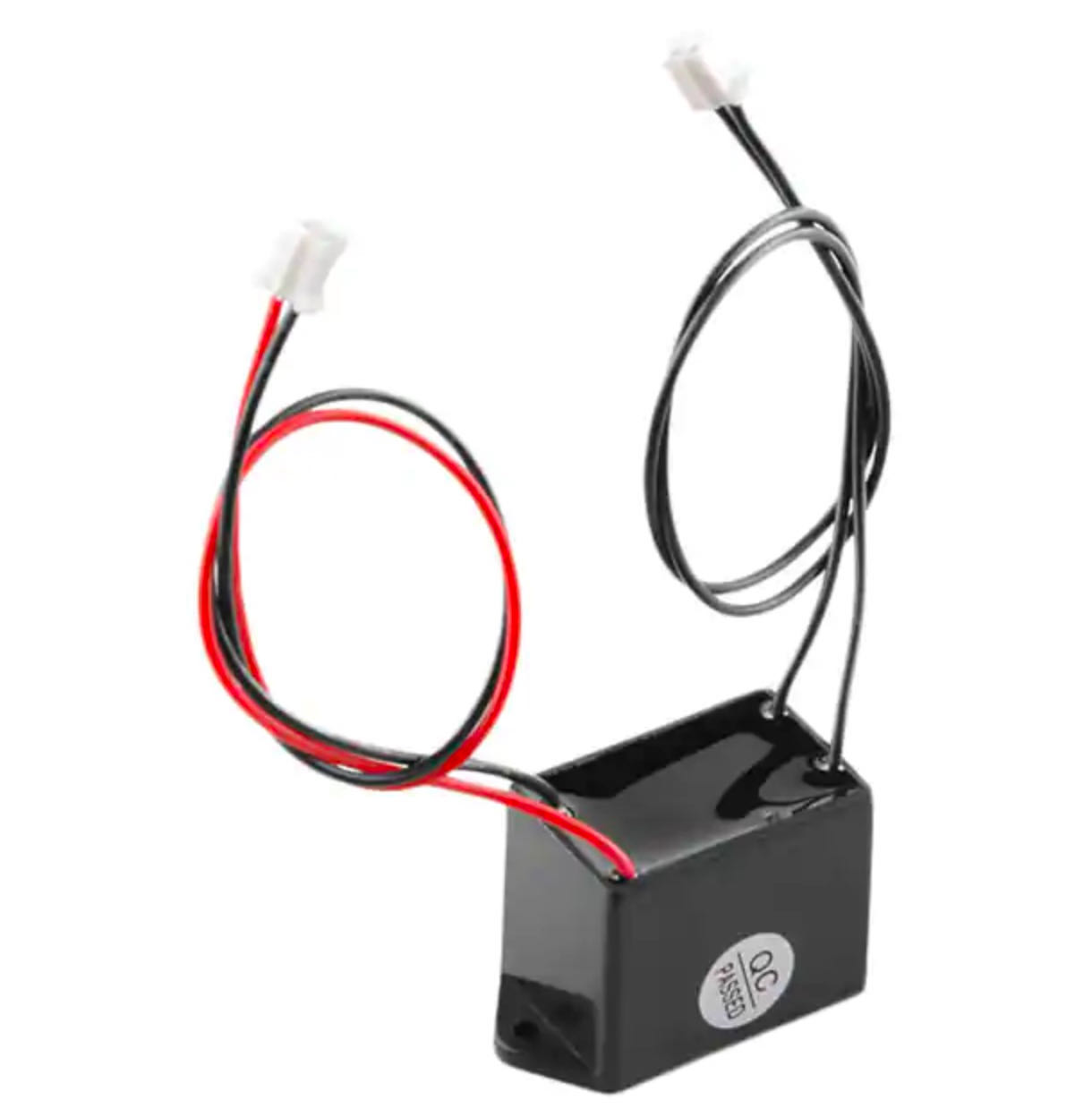
The particular EL inverter COM-10201 we bought accepts between 2.7-4.2V input and outputs 110VAC to drive EL wire. The wires both terminated with JST PH connectors. These are designed to plug directly into our EL Escudo or EL Sequencer (explained above), which i don’t have yet. Luckily you can drive EL wires with them directly.
The most important thing to note is that without a load capacitance/resistance, the voltage output can peak very high, up to 400Vpp (Voltage Peak to Peak)! This will damage the pass transistors and for this reason you should never run an EL inverter without EL wire attached
The data i found online about the COM-10201
Note 1: The inverters that we are currently shipping are not labeled input/output on the body. Instead, the new units have a red/black pair (supply voltage) and a black/black pair (output voltage). New pictures are forthcoming.
Note 2: Some real world testing revealed that this inverter can easily drive a 3m length of EL wire. When adding a second 3m length, the two get a bit dimmer, but still close to full brightness. Above 2 strings (6m) the amount of light is to low to be noticed.
Construction
EL Wire can be cut at any point along the line and will continue to glow to the point where it is cut. It’s recommended to cut at a 30° angle and immediately after cutting to apply an end cap to the wire. This will keep debris and moisture out of the wire and keep it lasting time after time.
You can also solder El wire but it a little tricky to work with. It is made of three wires, one large middle wire and two very thin ‘corona’ wires.
dutch site with basic Elwire information
How to control the ELwire
Dimming
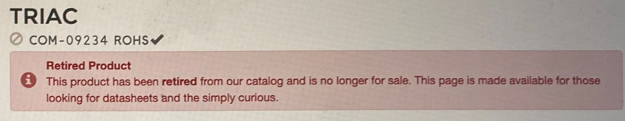
Found this site which has a tutorial about dimming EL wire but got stuck at the TRIAC not being available anymore. A TRIAC is a three terminal electronic component that conducts current in either direction when triggered.
Erwin was so thoughtful to point out to me that the tutorial is actually for 110V not 220V so suggested i would use a much higher Voltage, 600V instead of the 200V from the tutorial. Which in retrospective may have been a mistake since we need the AC to be high frequency.
The description of the TRIAC on the site of Sparkfun: This is a sensitive gate TRIAC (also known as a thyristor) with a 200V blocking voltage in a bread board friendly TO-92 package. Use a TRIAC to control an AC load (like EL wire, small incandescent lamps, etc) from a DC source.
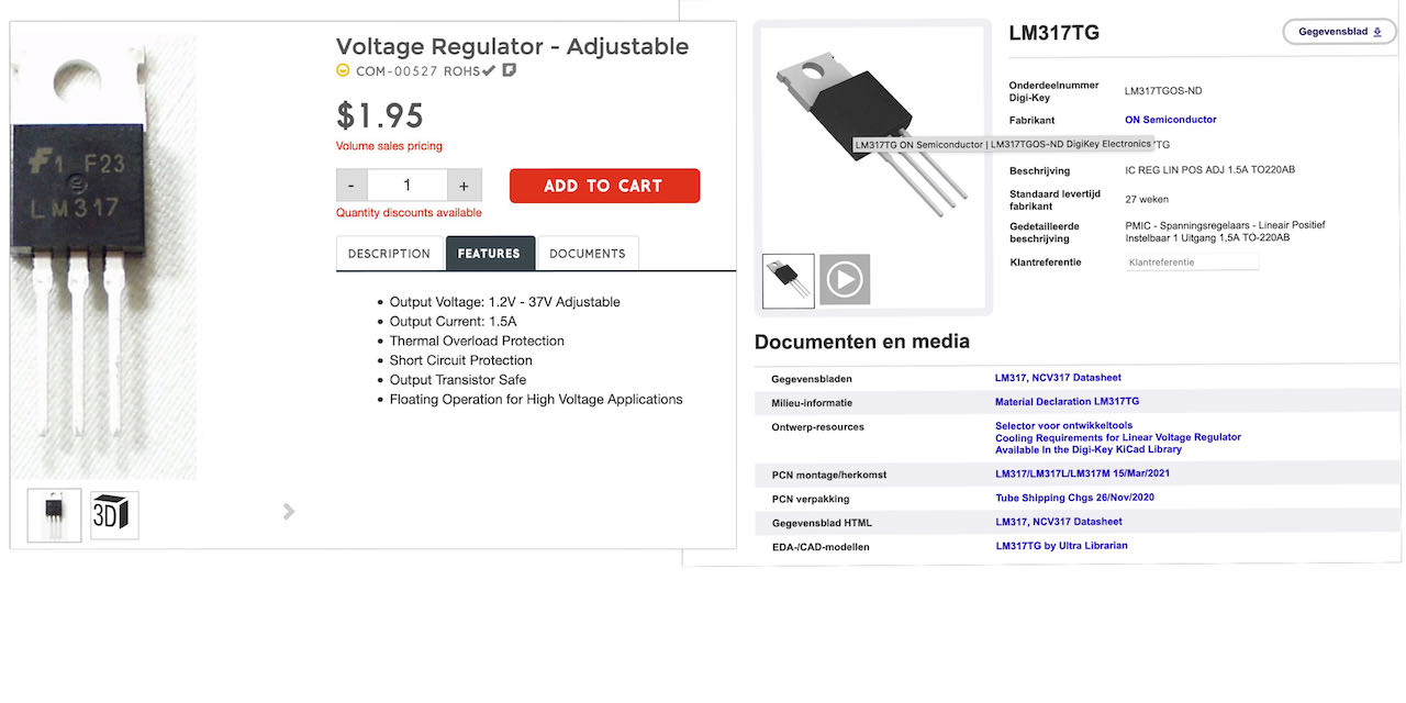
For the Voltage regulator it was a bit easy, could just use the type number to find it digikeyorder
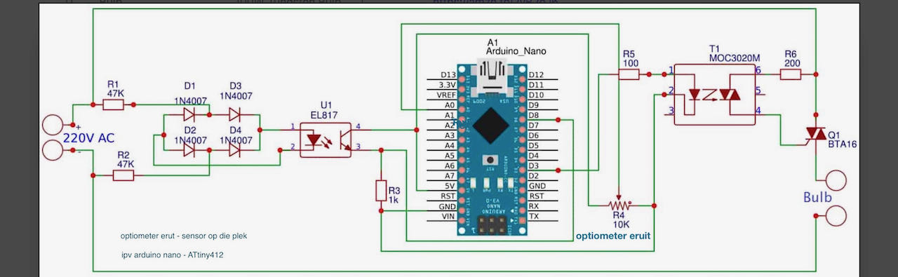
This is the schematic thats also on the dimming EL wire by Rikkurd site
Can’t seem to locate the TRIAC on this one so getting a bit confused..
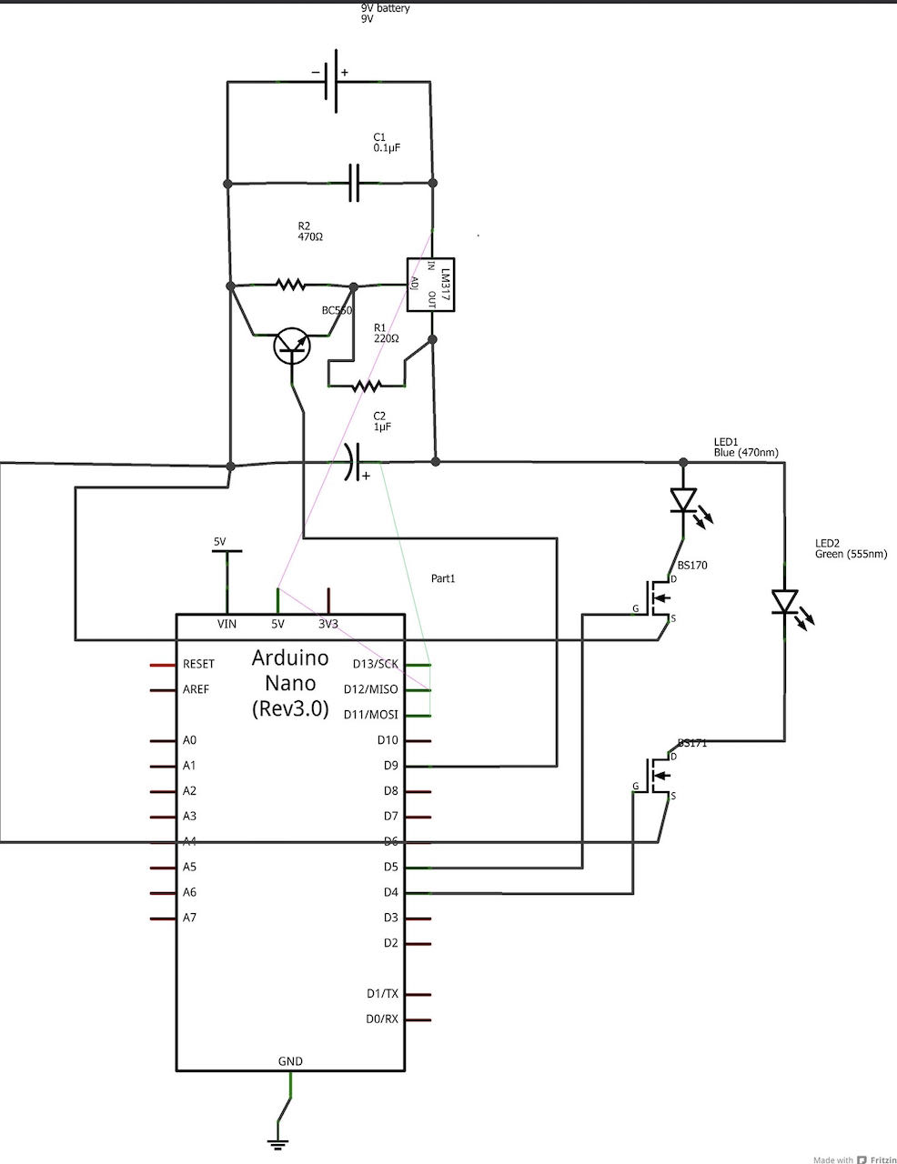
also the picture doesn’t help me
I am a bit afraid to get lost in this so will do a bit of more research before deciding. My main worry is that i don’t understand how much Voltage the TRIAC should block.. should it the 200V or the 600V?
No dimming but just blinking
Found a few different versions and many opinion on how to make EL Wire blink
The relay version from 2013
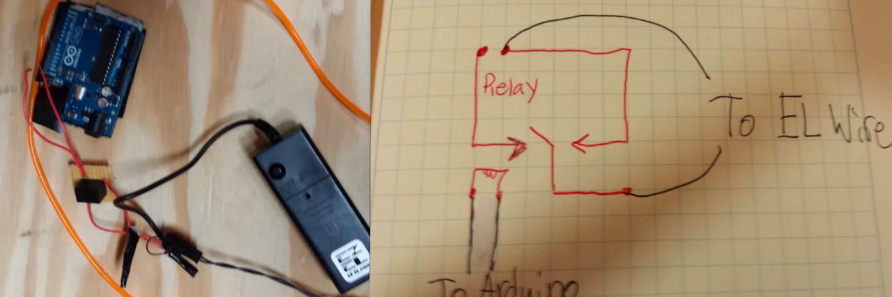
The inside of the controllers with inverters that come with the ELwire, which holds 2x AA battery.
Things i will need for the relay version:
- ESP32
- EL wire
- El inverter (3V)
- relay 5V
The TRIAC version from 2011
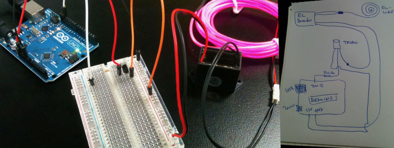
Things i will need for the TRIAC version:
- ESP32
- EL wire
- El inverter (3V)
- TRIAC (funny enough not specified)
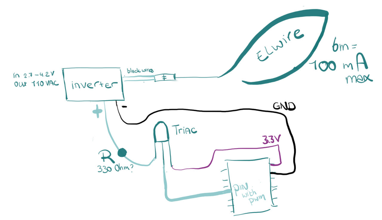
- 330 Ohm resistor - not sure if this depends on the length of the wire..?
- Connect the output wires of the inverter to the el wire
- Input wires of the inverter need to be connected to GND and 3V
- Put a TRIAC in between the power supple and the positive wire of the inverter
- The black wire is directly connected to the GND
- whenever you set the PINn high the TRIAC closes the circuit making the EL wire glow.
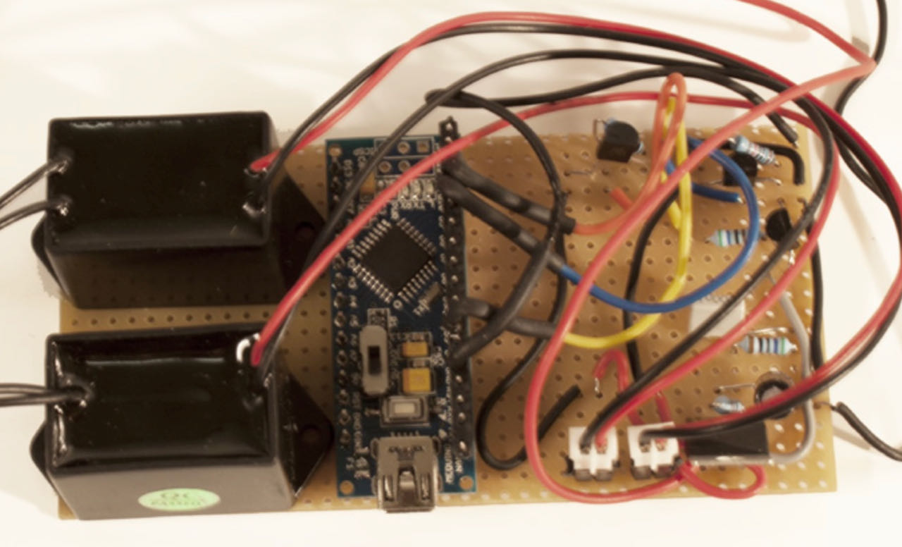
If i put it together i get something, like this:
Ready made boards
Another way of controlling El wire is a prefab shield to use in combination with an Arduino, they are called EL Escudo or EL Sequencer, which felt a bit like cheating but i ordered a EL Escudo Dos which will probably arrive next month so that i have the knowledge for future projects. The El Escudo Dos contains circuitry to safely switch high-voltage AC on and off, allowing you to create animated displays or whatever else your imagination can come up with.In addition to this shield, you will need Arduino headers, an inverter (a component that generates the high-voltage AC needed by EL wire), and the EL wire itself. There is a 3V-input version that can drive max 3m of EL wire, and a 12V-input version capable of driving around 10m of EL wire
- researching gave me so many different versions and options that i got a bit lost
 - when i understand more then the researching will also go more efficient
- keep on looking into learning programming