Revisions to final video based on comments from final presentation
After presenting my final project in the final presentation session, I received the feedback that the final project was good but the video needed the following elements to be demonstrated more clearly:
- Show the functionality of the temperature gauge more clearly
- Show voltage and current of the pelletier modules to make clear that there is power being generated by them
- Make it more clear that the fan is working.
Taking these comments into consideration, I performed another more controlled experiment that could better demonstrate the pelletier voltage and current and replaced the section at time 1:05 - 1:12
I also tried to indicate the fan flow being shown by pointing out the air flow in through the inner combustion holes at time 0:42-0:45. Below is the updated video.
Revised final presentation video
Furthermore, I have included the original videos so that they can be seen on their own here below.
Temperature, voltage, and current
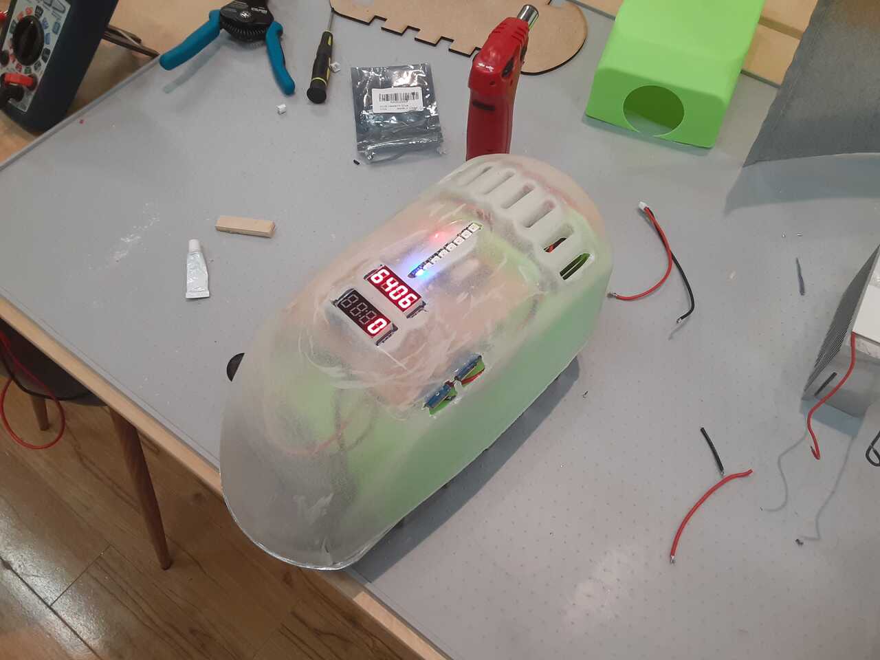
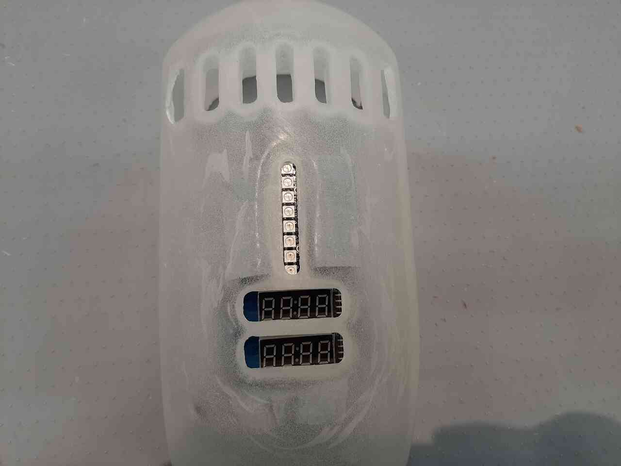
The videos below show the temperature, voltage, and current being produced by the heat. Notice that the LED bargraph increases over time as the pelletier plate warms up (temperature), indicating that there is sufficient heat being created to create current.
Also with the voltage and current, you can see that the voltage and current both increase over time as things heat up, the voltage gets up to around 6V and the current gets up to between 800 mA and 1200 mA. Another note, is that I only programmed the LED Displays to show three digits so when the current gets above 1000 mA the first digit does not get displayed.
Original videos so you can watch each indvidually
Fan
Lastly, here is a video that is demonstrating the fan flow, when you look closely, you can see the eddies being created and flame jets coming out of the holes that are in the inner combustion chamber wall. Also, the large flames that are produced from burning just a few pieces of wood is also a good indication that the fan is providing a lot of oxygen.
In the following sections I will discuss each element in detail. There are more videos demonstrating functionality of each system as the prototype was being constructed in the sections below.
Background
55% of rural Africans across the continent have little to no access to electricity as they try to cook in the nighttime . The PowerStove will immediately provide electricity for these families with a short payback period compared to buying a conventional stove and small solar panel. PowerStove provides a solution much more elegant than cooking without the benefit of creating electricity and/or the complexity of having to buy additional equipment
The PowerStove is designed for user’s with no training required. Simply fill the stove with biopellets, ignite them and you’re ready to cook while powering your electronic device through the USB port.
This two in one solution replaces your conventional charcoal stove and comes with the added bonus of electric power. No need to buy a solar panel, this stove powers while you cook. A similar stove has proven successful in Nigeria with little to know user training necessary.
Final project requirements
In this section I will go through and answer step by step all of the questions listed in the project requirements assessment page.
What it does
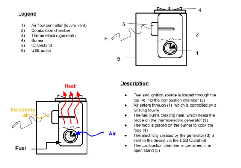
The Powered Stove converts heat from cooking into Direct Current Electricity using Thermoelectric Generators (TEGs). TEGs are thermo-electric component that take advante of the (Seebeck Effect)
The electricity is used to power a USB terminal suitable to charge a phone. Critical to the Seebeck effect is the requirement of a thermal differential. As such, a heat sink and fan are required on one side of the TEG to appropriately cool the TEG. The photo below provides a general overview of what it does.
IoT Component
Furthermore, the concept for this stove will have an IoT component that will measure and display the power it is producing and how warm the plate is and will relay this information via a ESP-32 module to a telephone app.
Who has done what beforehand
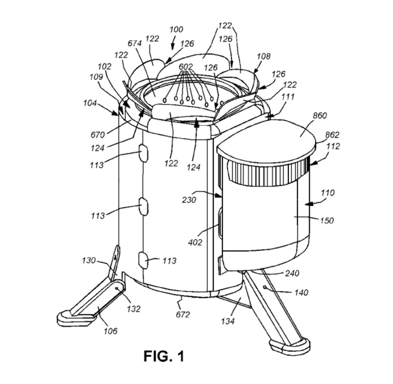
To date a commercial product called the BioLite exists. Much of my design is based on that. Details can be found here at this Biolite Link
There is also very good description of their invention in the Biolite patent application and shown in the photo below.
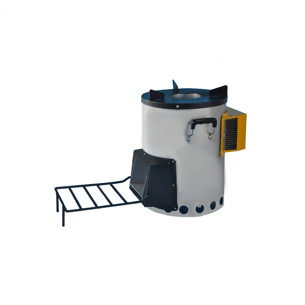
There have also been pelletier module stoves that have been developed and are sold on Alibaba as per the following link and the photo below.
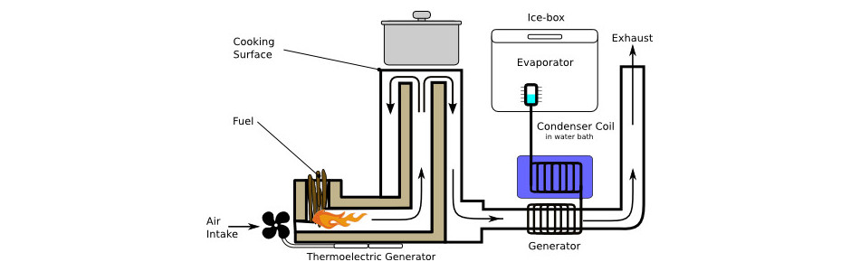
Lastly, a Fab Academy student Ferdinand Meier who made a trigeneration stove that could generate heat, cold and electricity from a woodfire. His project can be found at the following link. Below is a photo of his concept:
These resources will all be very great sources of imformation for future projects.
What I designed
For this project there are four main elements the were designed. They are:
- The combustion chamber
- The power unit and electronics
- The cover
- The IoT user interface
I designed and constructed each of these elements.
Bill of Materials
In this section I will present the bill of materials for each of the four main elements. It has been asked that we answer the following questions:
- Describe where they came from
- Describe how much will they cost
Below the bill of materials for each system is presented.
The total BOM cost for the project was $262.32 CAD or $209.86 USD
Excluding taxes and any shipping costs that may apply. Note that all prices in the following sections are given in May/June 2021 Canadian dollars.
1. Combustion Chamber
The combustion chamber is made of two concentric CNC milled sheets (more details below). The manufacturing processes and documentation regarding fabrications are shown in Wild Card Week
| Part | Quantity | Source | Cost | Link |
|---|---|---|---|---|
| 16"x36" Joist Panning lining | 3 | Home Depot | $9.88 | link |
| 12" x 12" x 3/16" Aluminum Plate | 1 | Metals Supermarket | $33.31 | link |
Total Combustion Chamber cost = $62.95 CAD
2. Power Unit and Electronics
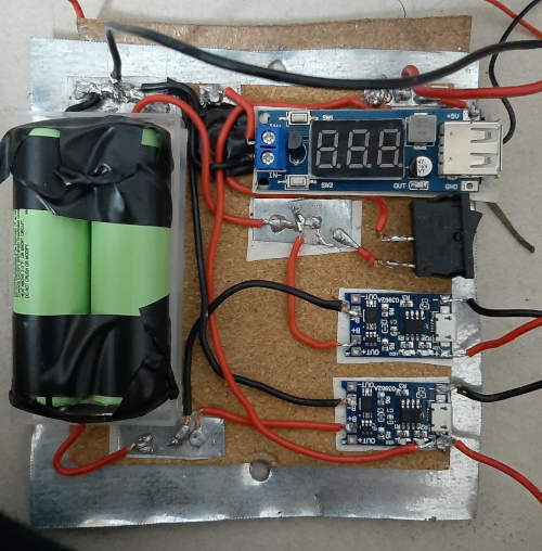
The electronics is made of two systems, a) the power systems which includes the pelletier modules, heat sink, fan, baterries, and charge controllers and b) the electronics which inclues the microcontroller system and design based on the Satscha kit, the input and output devices, the ESP 32 unit, and other electronic components.
a) Power Unit
| Part | Quantity | Source | Cost | Link |
|---|---|---|---|---|
| 5V Fan | 1 | Amazon | $13.99 | link |
| TEGs | 10 | Alibaba | $5.99 | link |
| 18500 LiOn Batteries | 4 | Amazon | $3.33 | link |
| Deep Fin Heat Sink 14271.5120mm | 2 | Alibaba | $8 | link |
Total Power Unit cost = $ 103.21 CAD
b) Electronics
| Description | Part | Package | Quantity | Source | Cost | Link |
|---|---|---|---|---|---|---|
| Microcontroller | ATMEGA328P-ANRCTND | TOFP-32 | 1 | Digikey | $2.52 | link |
| 16 MHz crystal | 535-9875-1-ND | SMD 11.4 x 4.77 | 1 | Digikey | $0.336 | link |
| Green LED | 1516-1073-1-ND | 1206 | 1 | Digikey | $0.284 | link |
| Blue LED | MCL-S250BL | 1206 | 1 | Digikey | $0.37 | link |
| Switch | SW262CT-ND | 6 x 6 x3.1 mm | 1 | Digikey | $0.98 | link |
| 10K Resistor | ERJ8GEYJ103V | 1206 | 4 | Digikey | $0.14 | link |
| 4.99 K Resistor | 311-4.99KFRCT | 1206 | 3 | Digikey | $0.03 | link |
| 499 Resistor | 311-499FRCT-ND | 1206 | 2 | Digikey | $0.103 | link |
| 0 Ohm Resistor | 311-0.0ERCT-ND | 1206 | 8 | Digikey | $0.017 | link |
| 22 pF capacitor | 1276-1203-1-ND | 1206 | 2 | Digikey | $0.062 | link |
| 10 uF capacitor | 1276-3038-1-ND | 1206 | 1 | Digikey | $0.182 | link |
| 1 uF capacitor | 1276-1204-1-ND | 1206 | 1 | Digikey | $0.149 | link |
| 100 nF capacitor | 732-CML1206x7R104KT50VCT-ND | 1206 | 2 | Digikey | $0.078 | link |
| 40 V 2A Schottky diode | 478-SD1206T040S2R0CT | 1206 | 4 | Digikey | $0.39 | link |
| 20V 4.7A P-channel MOSFET | TSM500P02CXRFGCT-ND | SOT23 | 3 | Digikey | $0.68 | link |
| 5V linear voltage regulator | LM2940IMP-5.0/NOPB | SOT23 | 3 | Digikey | $1.49 | link |
| N.O. Temperature Switch | 12080600ux0947 | Normally Open | 1 | Amazon | $1.55 | link |
| Toggle Switch | KCD1-5-101-CX | SPST | 1 | Amazon | $2.59 | link |
| ESP-32 module | ESP-WROOM-32 | 19 PIN | 1 | Amazon | $14.50 | link |
| 25 V Volt Sensor | Yanmisfmadgin8y2 | - | 1 | Amazon | $3.52 | link |
| +/- 5A Current Sensor | ACS712ELC-05A | - | 1 | Amazon | $4.45 | link |
| Temperature Sensor | DS18B20-3M-3 | - | 1 | Amazon | $9.33 | link |
| 5V USB Outlet | PFM DC-DC | 0.9V-5V | 2 | Amazon | $1.64 | link |
| 5V 1A LiON Charge Controller | TP4056 | MicroUSB 5V 1A | 3 | Amazon | $2.06 | link |
| LED Digital Display | TM1637 | 7-Segment | 2 | Amazon | $2.95 | link |
| LED light bar | ES2812 5050 RGB | 8 LEDs | 1 | Amazon | $15.95 | link |
| 4x1 Female through Pin | - | - | 4 | Amazon | $0.025 | kit |
| 7x1 Female through pin | - | - | 1 | Amazon | $0.025 | kit |
| 2x1 JST through pin | - | - | 7 | Amazon | $0.175 | kit |
| 3x1 JST through pin | - | - | 1 | Amazon | $0.175 | kit |
| Male through pin | - | - | 1 | Amazon | $0.025 | kit |
| FR1 Copper Clad PCB Board | - | - | 1 | Carbide 3D | $1.00 | link |
Total Cost of Electronics Components = $83.96 CAD
3. The cover
The cover consists of the epoxy cover that was made using rotary casting methods described in the 12 - Moulding and Casting assignment. There is also an element that is 3D printed which contains the heatsink enclosure.
| Part | Amount | Source | Cost | Link |
|---|---|---|---|---|
| 2 -part epoxy resin 500 mL bottles (1L) | 300 mL | Fibertek | $36.60/L | link |
Total Cost of Cover = $12.20 CAD
Parts and systems
As mentioned the systems described are as follows:
- The combustion chamber
- The power unit and electronics
- The cover
- The IoT user interface
In the following subsections I will provide the details on the parts and systems and their functions.
1. The combustion chamber
The combustion chamber is meant to house the flame and provide the heat for power generation and cooking. There is an inner wall and an outer wall. The outer wall contains the vent hole and the inner wall has holes that allow the forced air from the fan to enter the combustion chamber in order to increase efficiency.
Version 1
Version 2
Next I will discuss the power unit and electronics.
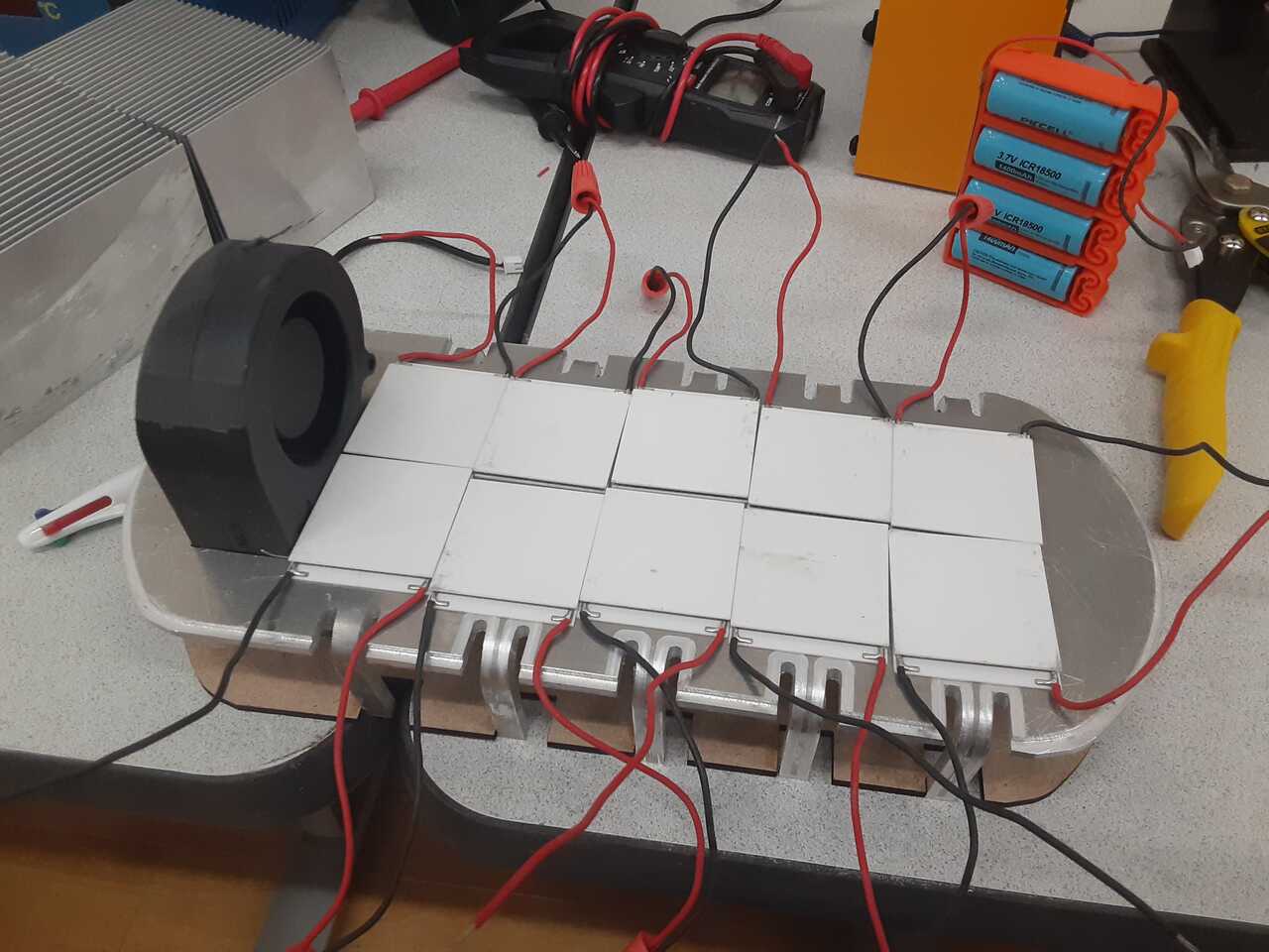
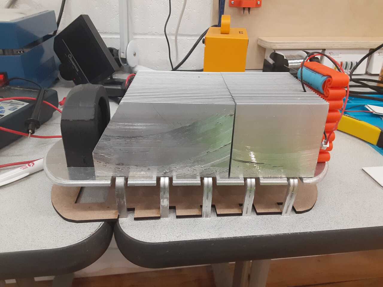
2. The power unit and electronics
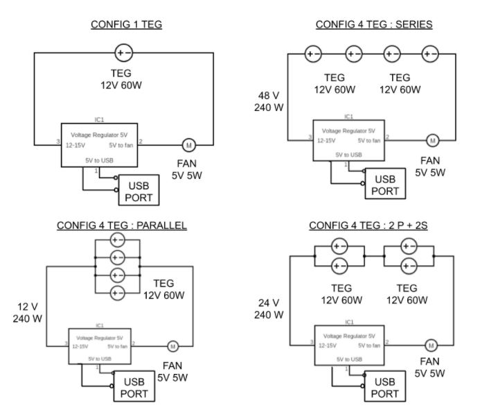
The powerunit is the system that converts the heat into electrity and powers the circuit board and electronics. It uses 10 thermopeltier modules (2 parallel sets of 5 wired in series) that are mounted to an aluminum mounting plate that conducts heat from the combustion chamber via the legs. The pelletiers are cooled using the heat sinks and the fan which draws air across the heat sinks through the windbox.
The unit is activated using a thermal switch that closes when the plate reaches 50 C. There is also a built-in by-pass switch that can be used if you would like to use the battery pack to charge your phone.
The electricity from the pelletiers is diverted either directly to the USB outlet or to charging the batteries based on the voltage provided at the p-channel mosfet.
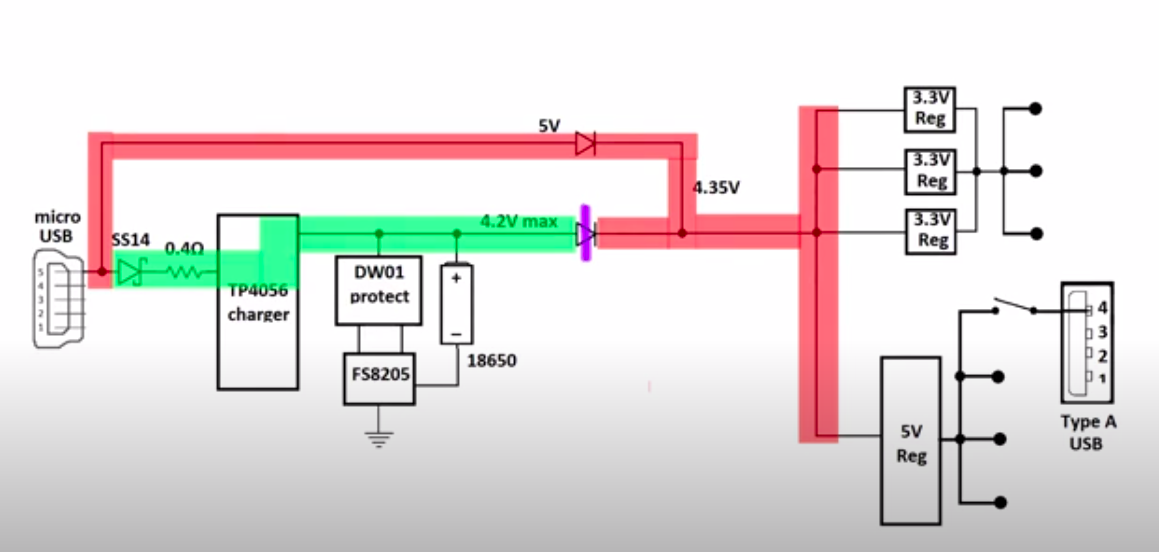
The voltage is then stepped up through the USB modules and used to power the AT-MEGA chip. The chip reads from the voltage sensor the current sensor and the thermocouple and outputs the values of current and voltage to the two TM-1637 displays, and indicates the temperature on an LED bargraph using the NeoPixel LED strip.
The AT-MEGA also sends the temperature, current and voltage values via I2C when requested by the ESP32. The board design is shown below:
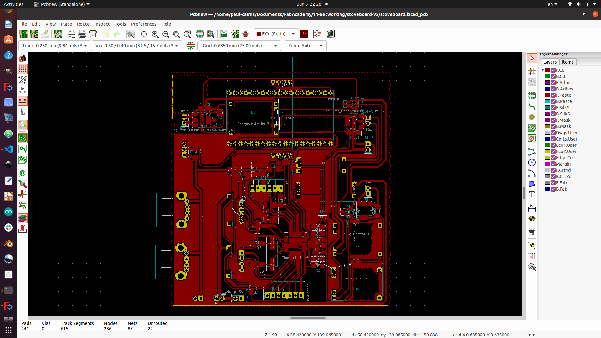
the AT-MEGA code can be found at this link
3. The cover
The cover is the outer shell that houses the power unit and electronics. The circuit board is glued into the cover using a glue gun and the wires are connected to it using JST connectors. Lastly, the cover was held on to the mounting plate using glue, but that was insufficient for the temperature, therefore metal bands will be used in the future.
Stickers were added to the cover using the vinyl cutter (not shown here, but can be seen in final video at the top of the page).
4. The IoT user interface
The IoT user interface was programmed in HTML and Java and uploaded onto the ESP32 board. The HTML page is accessed by using the IP address of the ESP32. Details regarding this development are given below.
The IoT user interface takes the Voltage, Current, and Temperature readings and displays them graphically on a IP based webpage that can be accessed by any device that is on the same network.
the html code and ESP32 code can be found at this link at should be kept together in the same folder.
Processes used
The processes to be used will be borken down by system as follows.
1. The combustion chamber
The combustion chamber is comprised of the inner chamber, outer chamber, bottom, legs, and mounting plates. The fabrication processes will be described as follows:
- Inner chamber: 2D design, sheet metal cutting with large format CNC, riveting
- Outer chamber: 2D design, sheet metal cutting with large format CNC, riveting
- Mounting plate: 2D design, sheet metal cutting with large format CNC, bending with the press
- Bottom: 3D design, sheetmetal cutting with large format CNC, forming/drawing using MDF die discussed in wildcard week
- Legs: 2D design and CNC milling of an aluminum plate, followed by bending using a press-break and hand powered hydraulic press.
2. The power unit and electronics
The powering unit and electronics comprises of the power system which includes the pelletier modules as well as the electronic system such as the circuit board. The processes used to produce and assemble each are discussed below:
- Pelletier modules and heat sinks: these were sourced and glued to the mounting plate using thermal paste and the connections were made using soldering techniques
- Circuit Board: PCB design, milling using a small CNC of a copper PCB board, soldering
- Battery holder: 3D design and additive manufacturing through 3D-printing
3. The cover
The cover consists of two elements, the cover, and the heatsink enclosure:
- The cover: designed using 3D modeling and made using rotary casting techniques covered in the Moulding and Casting Assignment
- Heat sink enclusore: designed using 3D modeling and manufcatured using additive manufacturing (3D printing)
4. The IoT user interface
The IoT interface was all done completely using programing on the Arduino IDE and HTML code with JavaScript to produce the webpage.
Questions that were answered?
After the work completed the following questions were answered:
- Is it possible to produce sufficient electricity from heat using pelletier modules ? Answer : Yes, but at what economic cost and how reliably?
What worked and didn’t work
Things that worked
- The combustion chamber worked extremely well
- The fan was very effective at producing a highly efficient combustion flame
- The thermocouple and temperature gauge worked perfectly
- The thermal switch worked well and was able to turn the system on when temperature was reached
- The AT-MEGA program was highly effective and produced excellent results on the serial monitor
- The rotary casting worked surprisingly well, more care can be taken in the future to reduce bubbles which resulted in the frosted look
- The ESP32 was highly effective at passing values to the HTML page on the local network (there were issues with the I2C communication bus between the AT-Mega and ESP-32 though)
- The interface on the HTML page worked flawlessly
Things that didn’t work
- In this project, most of the electronics worked until they were finally packaged and run, which seems to indicate that the traces may have been too thin for the current.
- The copper began to oxidize and destroy the traces overtime.
- I had difficulties getting the I2C connection working correctly, this may have been a trace or programming issue, further debugging may be necessary.
- The first version of the insulation (laser cut particle board) was not heat resistant enough and caught on fire during the final test.
- The voltage sensor stopped working on the first version of the board, again this may have been a trace issue, a newly designed board will be necessary.
How it was evaluated
In the applications and implications week I set the following standard of evaluating success:
“The project will be considered a success if the Stove is able to produce electricity, charge the batteries, and output results to the app.”
I would say that overall the project was a success, with the caveat that better results could have been achieved and can be achieved in the future
Implications
I would say that in order to make this product marketable to the African market a siginificant amount of simplification and cost reductions will be necessary. For this course I added all of the bells and whistles in an effort to ensure that I met all the criteria of the Fab Academy program.
Recommendations for simplified versions would include:
- Remove the IoT elements and I/O and simplify to simply a peletier with a USB and charge controller/battery pack
- Work to reduce the costs of the combustion chamber
Files
The files for the final project are given based on the system in the links below.
Combustion Chamber
- blank.dxf
- bottom.stl
- die.stl
- guide.dxf
- punch.stl
- plate.stl
- plate.dxf
- platepocket.dxf
- outsidesheet.dxf
- insidesheet.dxf
PowerUnit
Circuit board
- Kicad Project Included Eeschema and pcb files as well as project specific footprints
- Stoveboard trace
- Stoveboard holes
- Stoveboard edgecut
Programs for Ardunio IDE
Cover moulding/casting files
Project development history and construction details
In this section I will elaborate the entire history of the development of the prototype including work done prior to FabAcademy, through work done as part of the assignments towards this project.
Concept development
In this section I present the original concept and sketches that originated this project.
Combustion chamber assembly
The combustion chamber assembly mates with the electric generator assembly. The sketch below illustrates the concept for how it will be constructed for this prototype
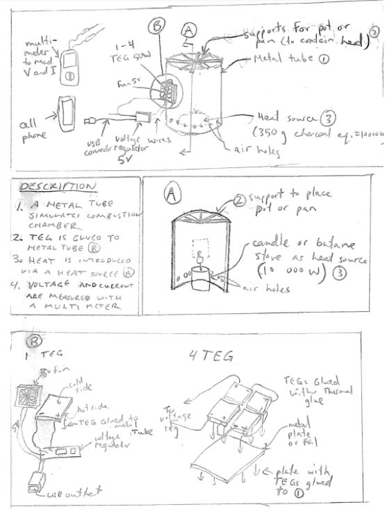
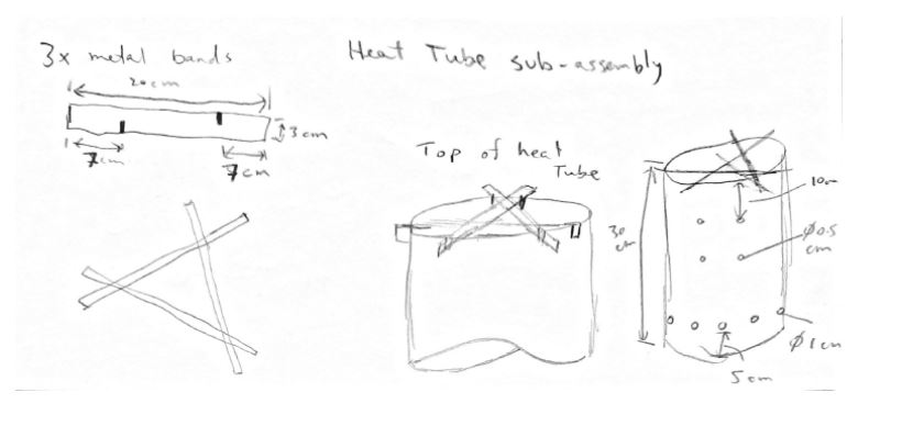
Electric generator assembly
The eletric generator assembly contains the TEGs and the cooling fan and heat sink. The sketch below illustrates the concept:
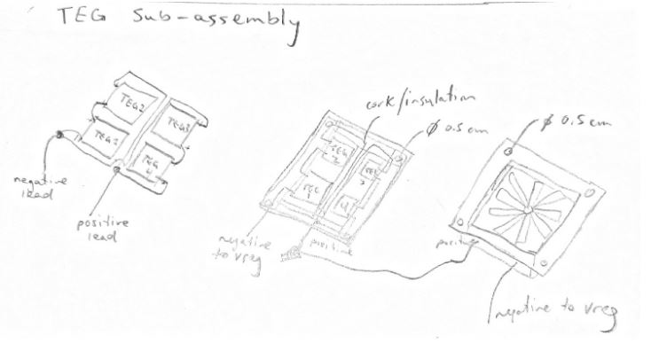
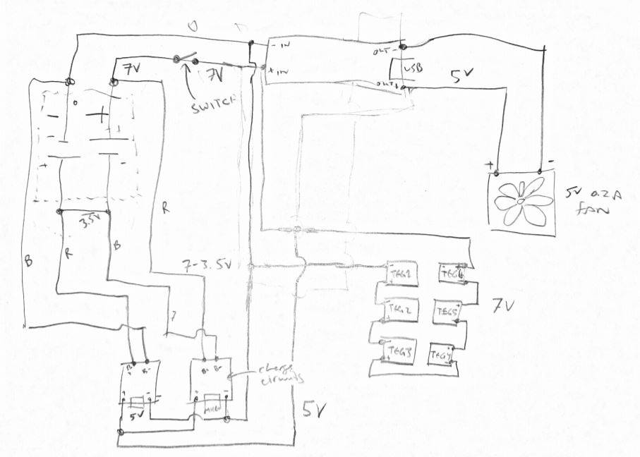
Electronic Assembly
The last assembly includes the wiring for the LiOn batteries, charge controller, voltage regulator and USB port. The first spiral used soldered wires and the next spiral will use a circuit board and will add temperature sensing as well as an LED bar graph.
History of my work on this concept
Prior to starting the FabAcademy, I had built a very first prototype of this concept as a way to learn the main subassemblies and where to improve the development. Below is a video of the first prototype:
In the first prototype, I proved the concept of using heat to produce suffient amount of electricity to power the fan and cool the back side of the TEGs.
Overall development goals (spiral developments)
In the first prototype, I experimented with using the TEGs to produce sufficient electricity to power a 5V fan. Although successful. There were many improvements that could be made. Below is a list of the improvements to be made.
Improvements required
- Construction of a better heat sink
- Construction of a better TEG
- Creating a circuit board rather than using wires and solder
- Adding a temperature sensor with an LED bargraph similar to the biolite
- Creating a more aesthetic housing for the electronics assembly
Spirals
Using the improvements listed above, below is an idea of the spirals that could be followed over the evolution of the project
- Completed prototype as is (TEGs that power fan)
- Addition of a heat sensor and led bargraph
- Refinement of heatsink assembly
- Custom build of the TEG
Objectives for this course
In this section I will discuss the next stage of development as my prototype evloves and how I plan to make it more responsive
Primary objective
In this course I intent to focus in on Spiral Step 2: Addition of a heatsensor and led bargraph. The objective is to build a heat sensor system and not focus so much on the combustion chamber. The BioLite video below illustrates the objective
Secondary objectives
The secondary objetives would be to successfully attach this electronics sensing assembly to an existing stove configuration and power it using off the shelf TEGs and heat sinks.
Moonshot
The moonshot would be to make my own custom heat sink and TEGs
Progress to date
As I have progressed through the weekly assignments, I have aimed to pick a design that applied to my final project as often as I could. As a result I was able to test and prototype various elements across various weeks. The list of work per assignment is as follows:
- Assignment 3 - CAD: Did a first draft of my models in FreeCad
- Assignment 4 - CNC: Flattened out my inner ring to practice milling my sheet metal using vinyl
- Assignment 6 - 3D Printing: Printed test pieces of the TEG cover so I could test my modelling skills
The following sections below illustrate how I have been working towards my final project throughout the weeks.
Computer Aided Design
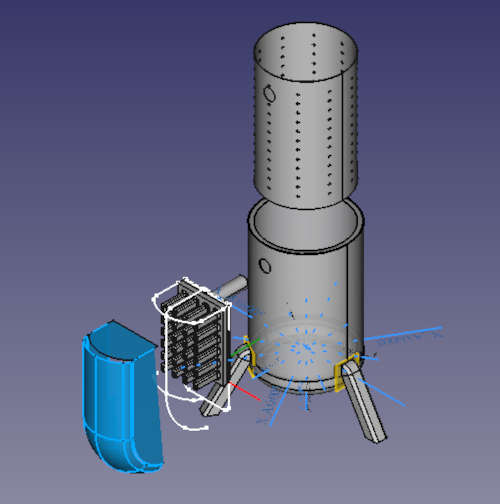
To date I have completed a overall concept of the final project, a stove that generates electricity for cell phone appliances and other low voltage DC electronics. An expoded view of the final 3D model is shown below
To create this model various computer aided design skills were needed both in Inkscape, and in FreeCAD including:
- (Making a sketch and constraining it)
- (Creating a datum plane)
- (Parameterising a sketch - includes Spreadsheet Workbench discussion)
- (Creating a shapestring)
- (Making a sketch and transforming it onto a surface - includes Surface Workbench)
- (Pad and Pocket (Extrude and Cut))
- (Sweep
- ([Multi Transform - linear and polar](https://youtu.be/
- (Make a union between two bodies)
- Make a cut between two bodies (same link as above)
- (Linear array)
- Polar array (same as above)
- (Bend)
- Flatten (same as above)
- ([How to make surfaces](https://www.youtube.com/watch?
- (Creating an assembly)
- (Mating parts)
- (Meshing and exporting your CAD file as a .OBJ for 3D printing or Rendering)
- (Rendering Your Assembly using Blender)
- (Rendering using CadRays)
Computer Controlled Cutting
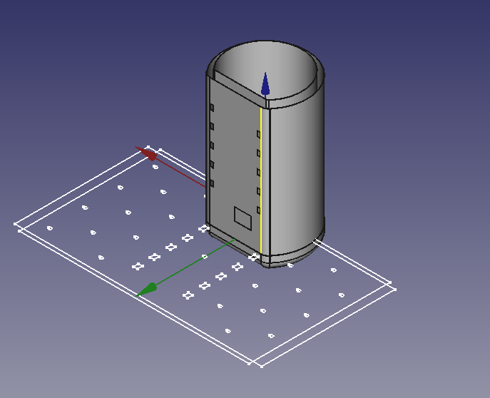
For this assignment I elected to practice laser cutting a piece for my final project that I will eventually want to mill with a CNC out of sheet metal. I wanted to practice taking a circular object, and flattening it out so that you can cut holes in it before bending and riveting it together. To test this out, I made a parametric design of the combustion chamber internal tube shown in the image below.
I then created a flattend version of this sheet in cad to use as the basis for my sketch export to SVG. The photo below provides a view of the CAD file with the part flattened.
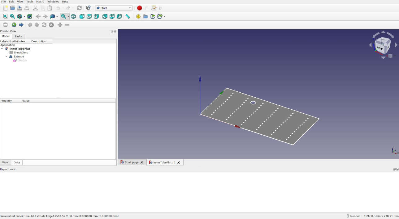
To make the model parameterized I had to perfom several calculations using the FreeCad Spreadsheets workbench combined with defining/constraining certain variables using equations. I did an in depth look at how to create a parameterized CAD file in Assignment 3 - Computer Aided Design.
For this week, I chose to focus my time on demonstrating how to take a parameterised sketch made in FreeCad, and prepare it for cutting with the laser. The video below demonstrates how to do this:
Once the .eps file had been created and imported into the computer that controls the laser cutter, it was simply a matter of cutting it and doing the final preparation. The video below documents that process.
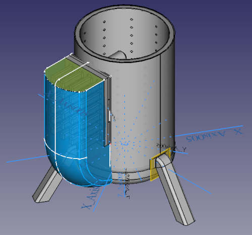
3D Printing
For this part of the assignment, I elected to model and print the cover for the Thermoelectricgenerator assembly that I will be building for my final project. As a reference, the image below illustrates the cover that will be necessary for my project. The cover is shown in blue.
in the following section I will discuss the modelling of it.
Modeling the piece
The pieve was modeled using Free Cad. The features that were used include:
- A sweeping loft for the profile
- Surfacing to build side walls
- Converting surfaces into a shell to create a body
- Converting shell into a solid
- Cloning the solid and scaling it down
- Using the scaled down and cloned solid to de a subtractive boolean to hollow out the bottom.
to ensure that the piece could not be created subtractively, and only using a 3D-printer I added two lips on the backside such that it would not be possible to get a machine into the top and bottom edges using any kind of 3-axis subtractive machining.
The final modelled piece is shown in the video below:
Printing the pieces
Unfortunately, the full scale piece could not be printed in the 3D printer because it was too big, and the time to print it would have been prohibitive. I therefore elected to print two scaled versions of the piece. Images of the two printed pieces are below:
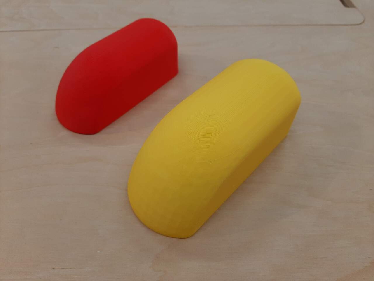
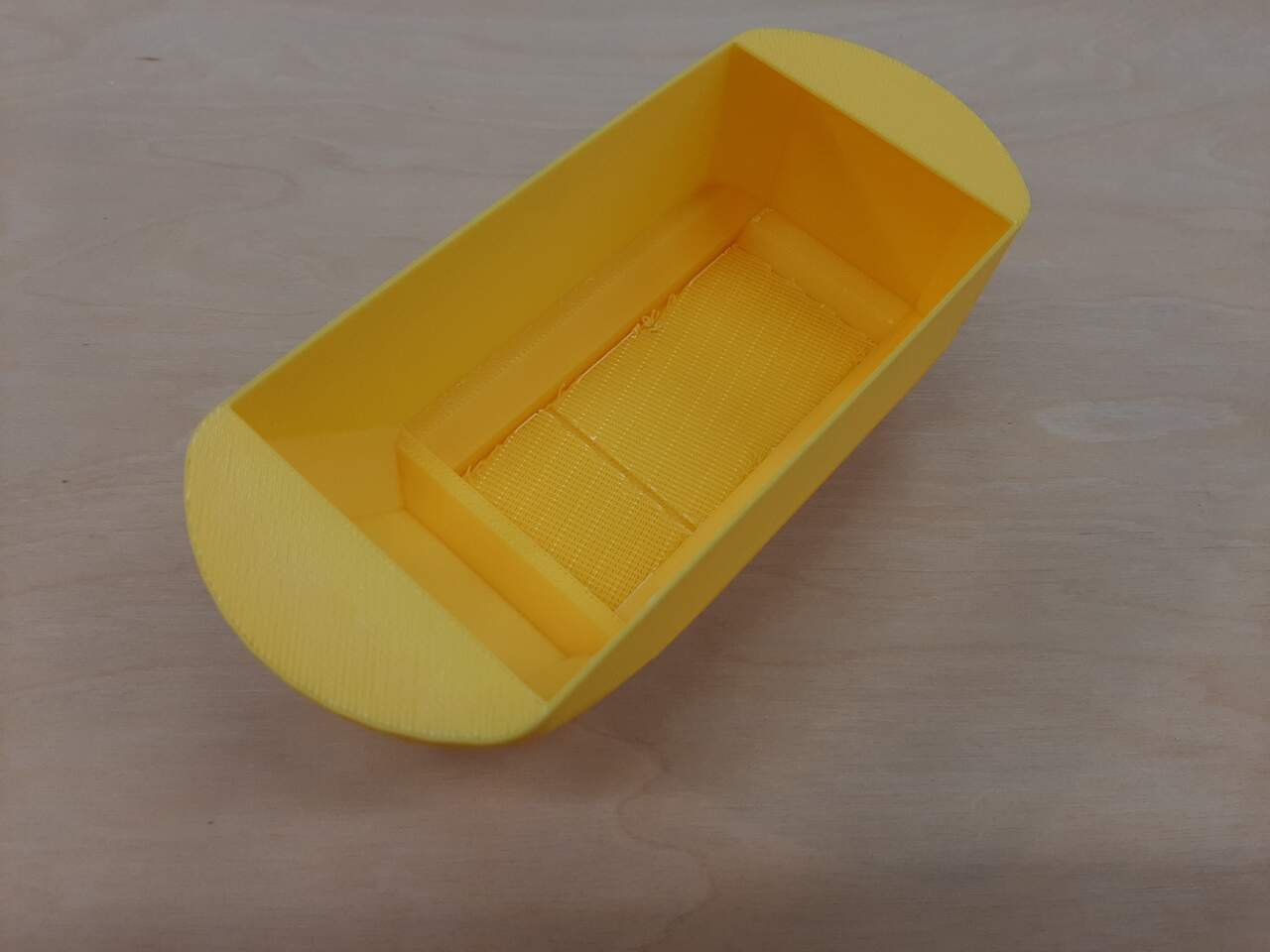
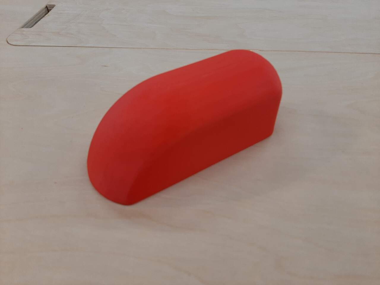
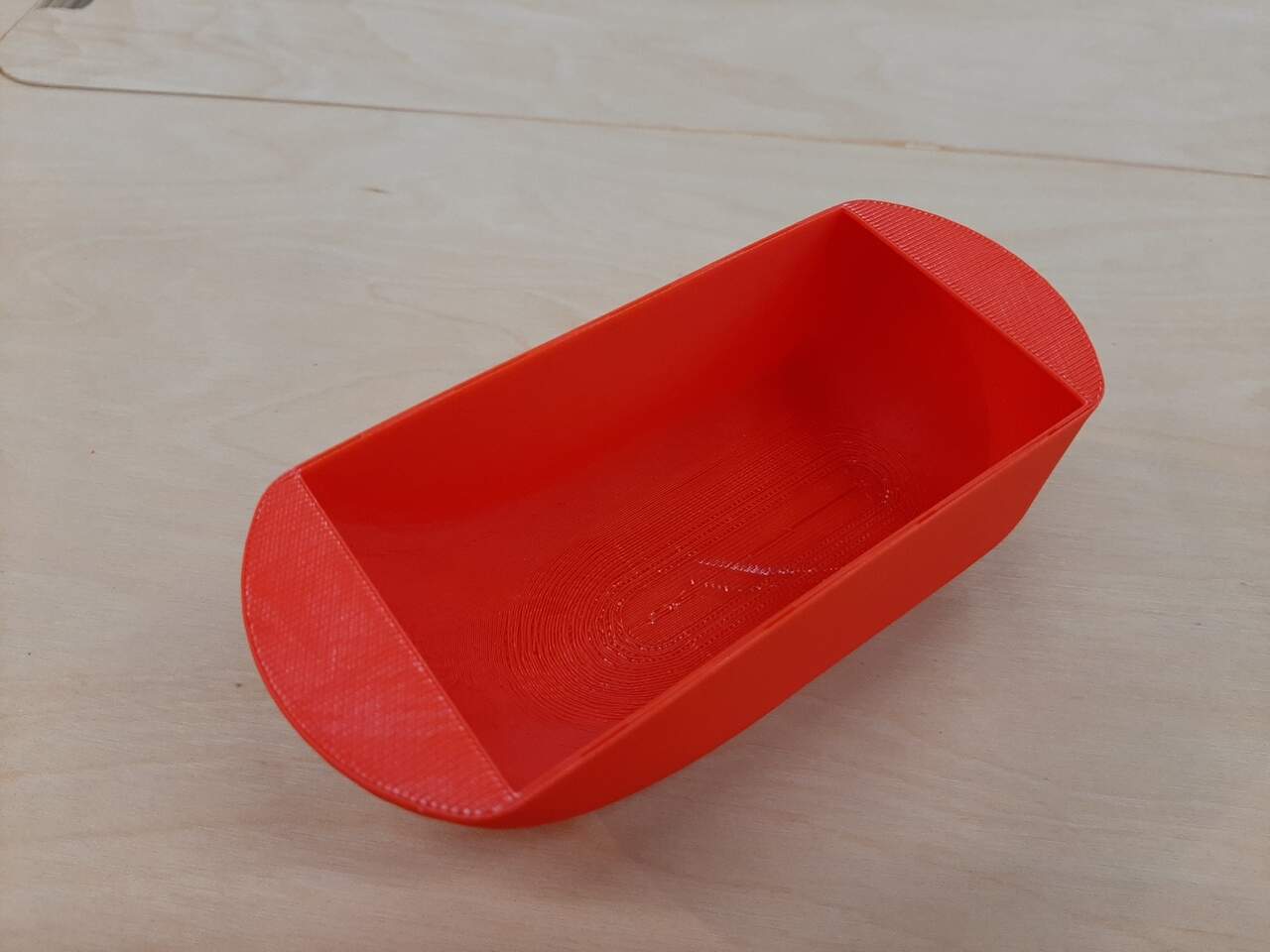
As you can see from the image, the two bottom walls make it not possible to make this cover subtractively. In theory I could have extended the bottom to make a completely hollow piece, but I wanted to remain as true to the original design as possible.
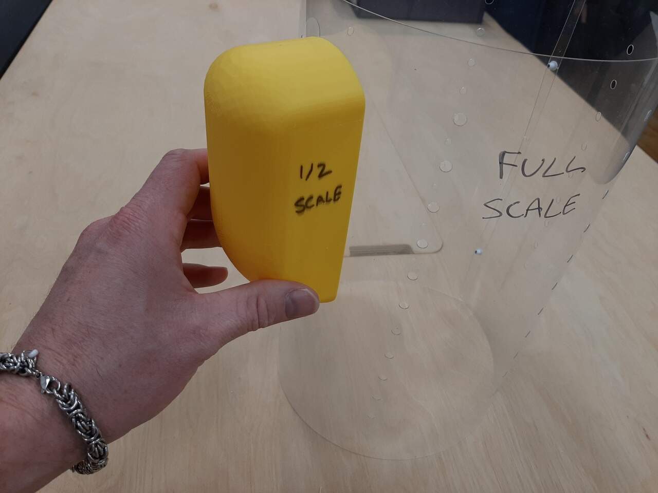
Dry fitting onto test piece from laser cutting
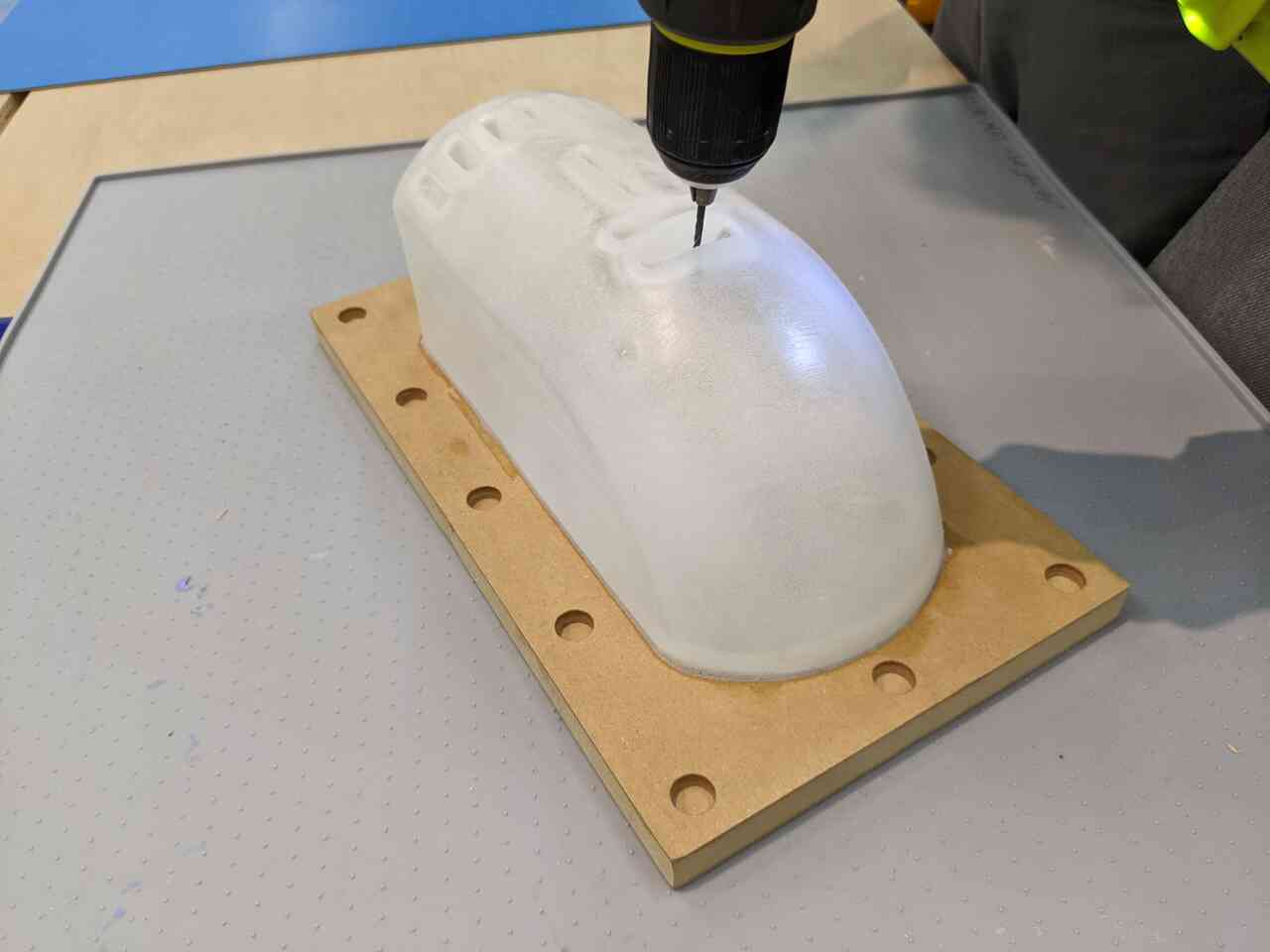
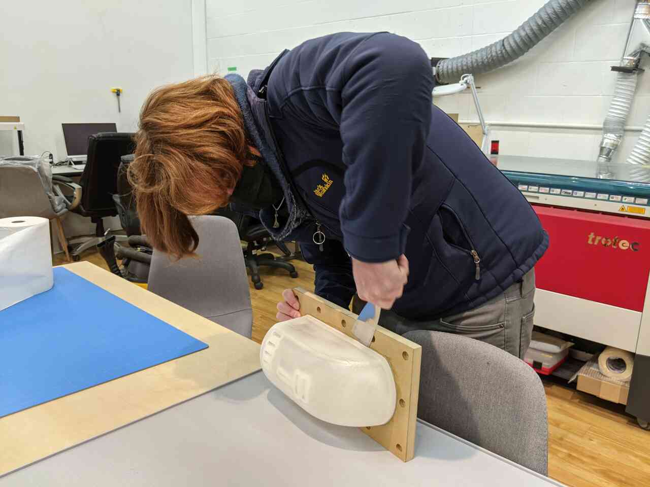
The last step was to dry-fit the cover to see how it would look with regards to the combustion chamber inner wall that I cut using the laser cutter as a proof of concept for milling sheetmetal later with the CNC. Below is a photo of the “mock-up” prototype with the 1/2 scale TEG cover and the full-scalle combustion chamber wall.
FIXTURING THIN SHEET METAL FOR CNC MILLING
Casting the TEG/electronics cover
During the moulding and casting week, i casted the full scale version of the cover using the rotary casting machine I built during the machine building week.
Here is a video of me removing the piece
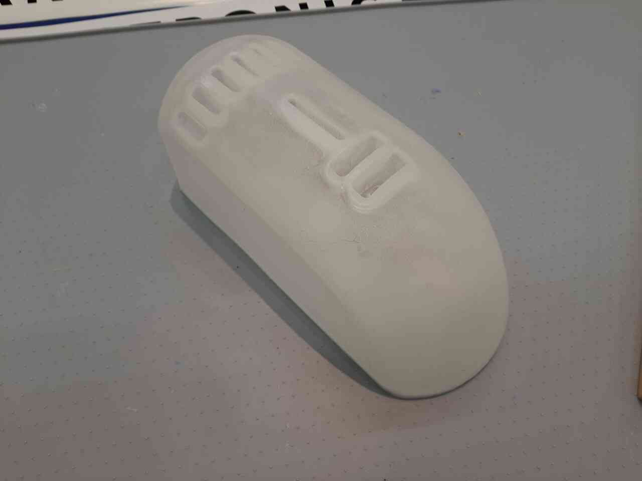
Here some images of performing the finishing touches
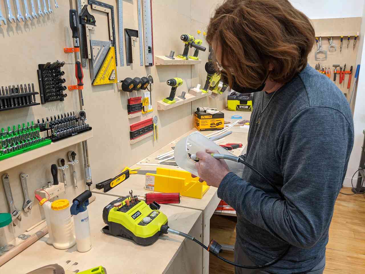
Next a video of the final result. Note that I was a little careless with the dremmel and ruined the interior finish which affected the overall appearance.
Lastly, some photos.
Testing the input and output devices
During the input devices week I tested the sensors (temperature, voltage, and current) to try and understand how to use them.
During the output devices week I outputed the voltage and current to LED displays and also linked the thermometer to an LED bargraph. The results are demonstrated in the following videos.