Individual assignment
This week was so challenging after professor Neil's class on Electronics Production, I was very confused especially because my educational background is medical & quality so it was difficult to understand all the new terminology.
Thanks to FabLab UAE instructor they helped me to learn the steps of the electronic production of PCB.
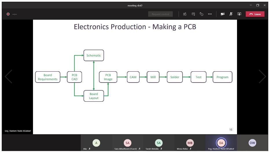
To sum it up this week will contain the steps shown in the screenshot below of our fablab UAE virtual lecture on Electronics Production
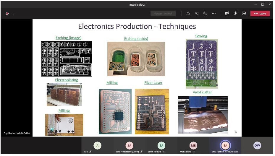
There are several techniques for electronic production of PCB as shown below.
I will use the Milling techniques to Building the FabTinyISP, My reference is in this link
1-MILLING
first I Download the PNG files for the traces and the board outline:
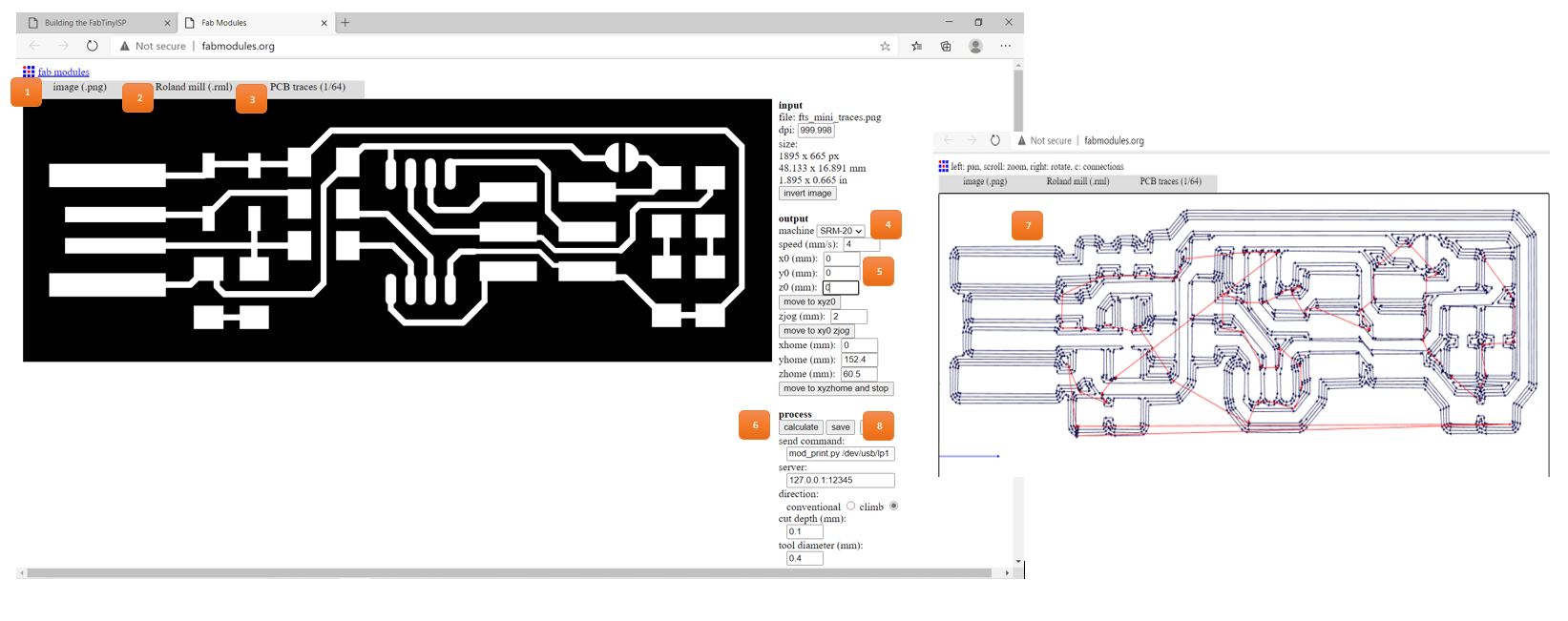
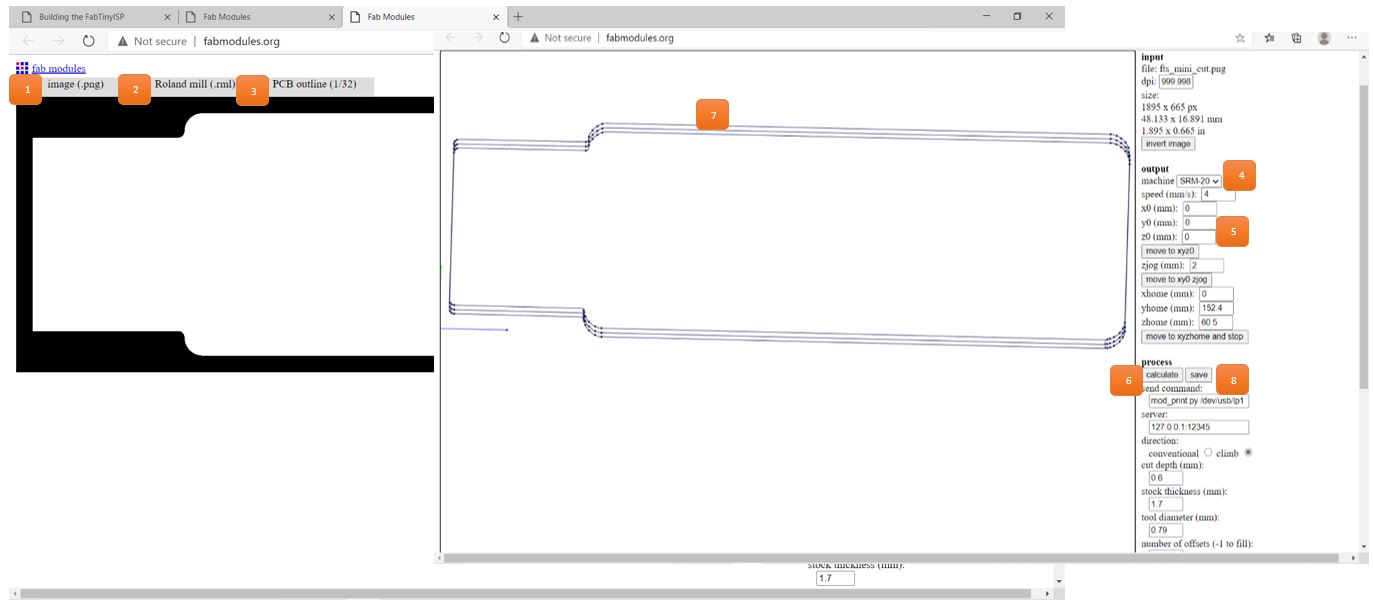
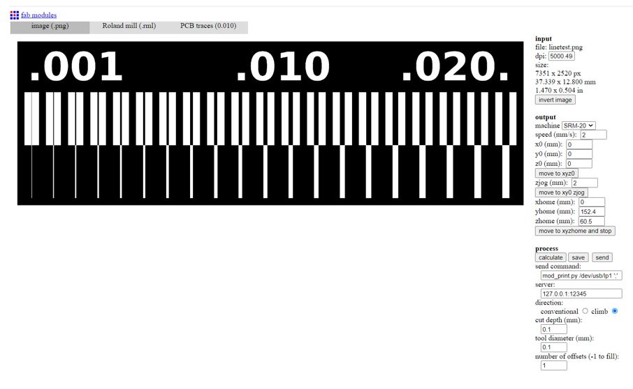
then I generate the toolpath from fabmodules, following the steps as shown in the below picture:
Traces
Outline
Saving the RML file & import it to a milling machine program, Roland SRM-20 was used to mill the PCB boards
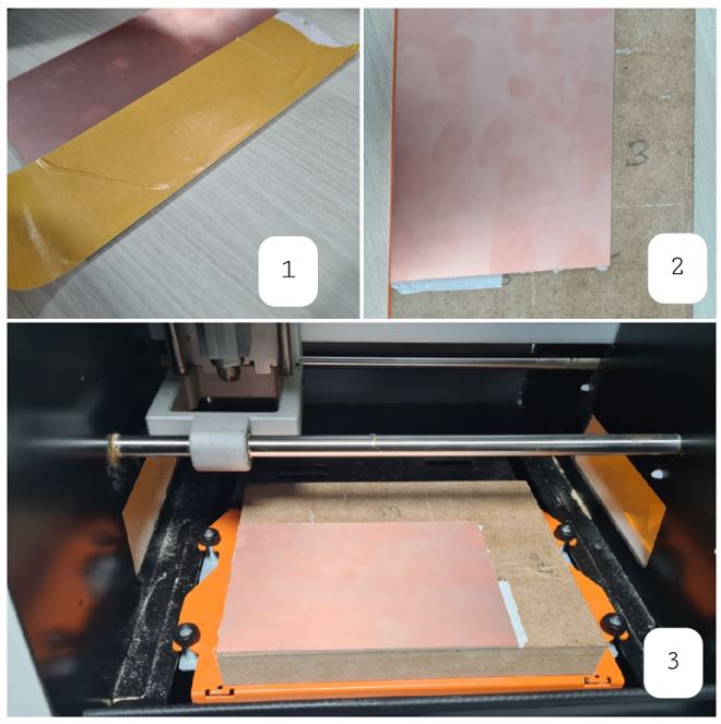
preparing to mill the PCB board I attach a double-sided tape to the back of the copper plate and finish the preparation as shown below.
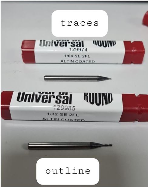
Then inserting the milling bit according to the traces and the board outline
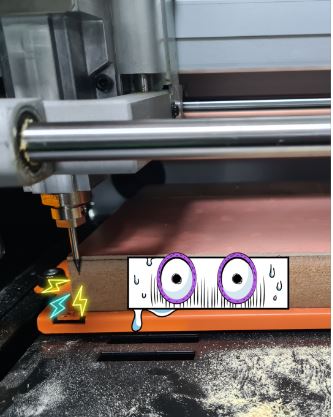
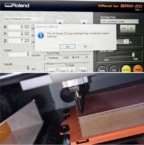
Then navigation the position of the bit & set the Z axis in this part be EXTRA carful because it may move very fast that the bit will broke.
Thanks god I didn’t break the milling bit
The X\Y & Z axis was set successfully
Done with the milling & I checked the board status it was perfect
2-SOLDERING
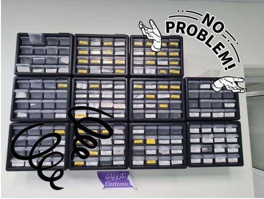
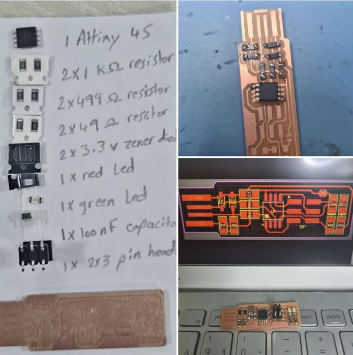
Now we will start the soldering journey, first I have to obtain the components from our COMPONENTS MAZE it was quite challenging
•1x ATtiny45 or ATtiny85
• 2x 1kΩ resistors
• 2x 499Ω resistors
• 2x 49Ω resistors
• 2x 3.3v zener diodes
• 1x red LED
• 1x green LED
• 1x 100nF capacitor
• 1x 2x3 pin header
Then installing & soldering the components in the correct orientation
This video shows you how to do soldering I record it when Eng.Maha was teaching me the soldering technique
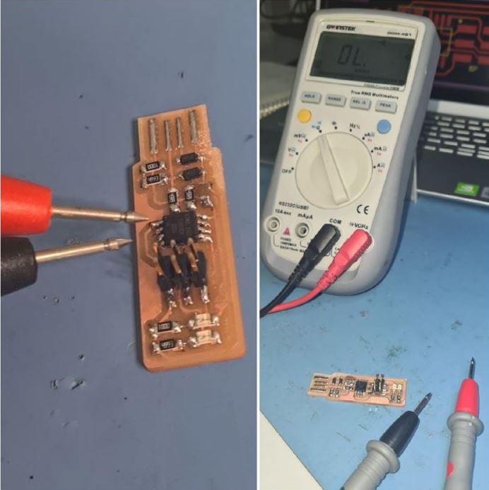
I reached the testing stage to check the connectivity, I used a multimeters and followed the connections showed on the image of the board, it was successful I will move to the programming
3-PROGRAMMING
I follow the steps that been documented by Eng.Maha in her website
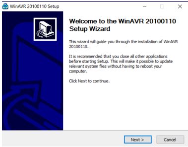
Step 1
Install WinAVR 20100110
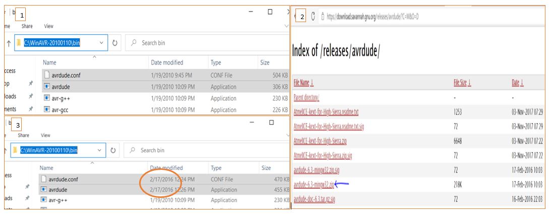
Step 2
Go to the folder C:\WinAVR-20100110\bin > delete avrdude.conf and avrdude > Replace the deleted file with newer version the avrdude-doc-6.3-mingw32.zip
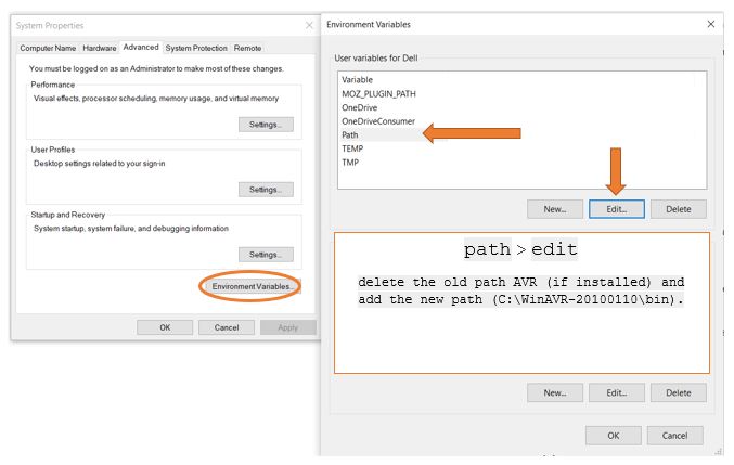
Step 3
Go to control panel > systems > advanced system settings > environmental variables > path
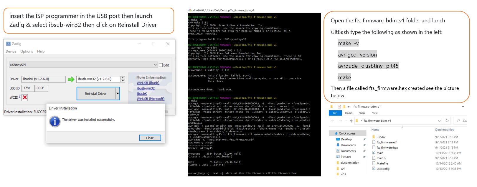
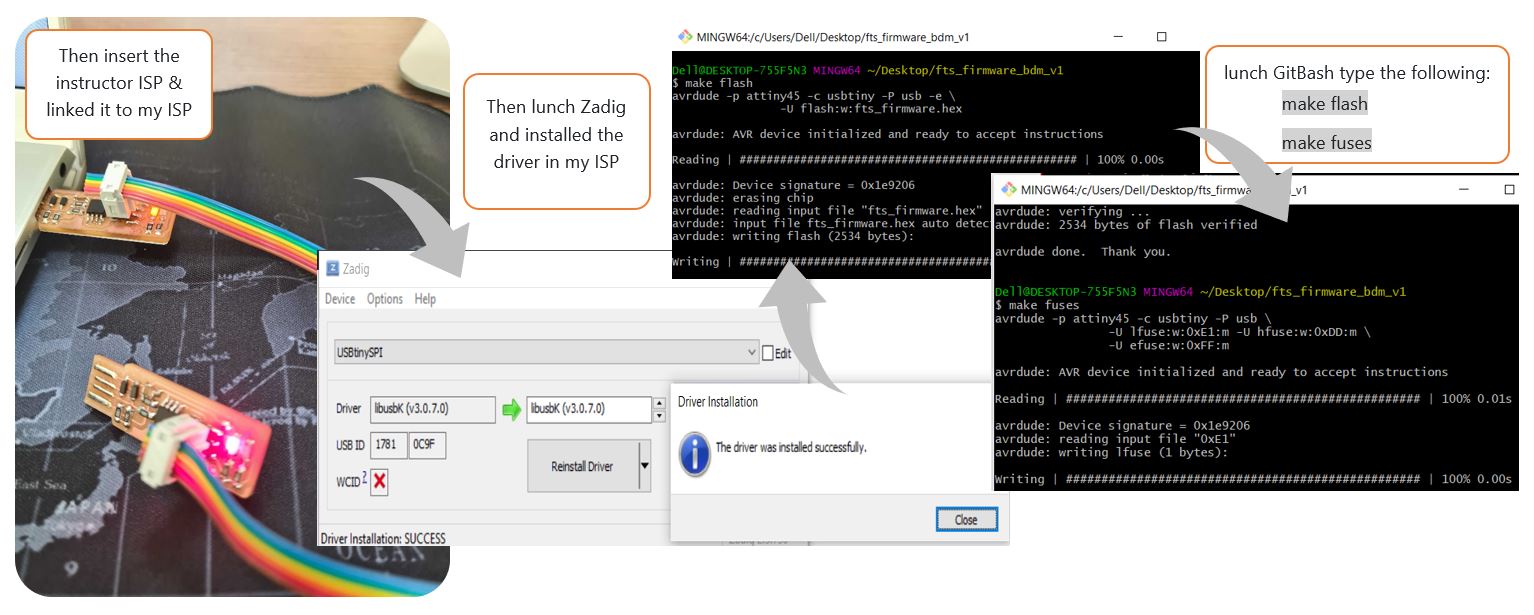
Then I insert my ISP in the USB port & my laptop recognize it then I started programing boards.
video shows my ISP programming other board
Group assignment (Link)
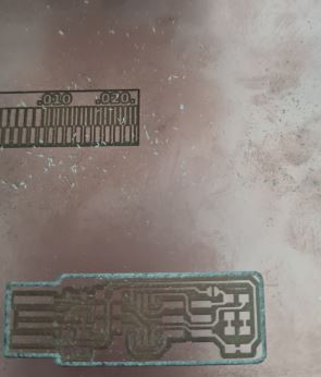
My part was to do line test for 0.1 v-bit Climb. I started by generating the toolpath from fabmodules & setting the parameters as shown below:
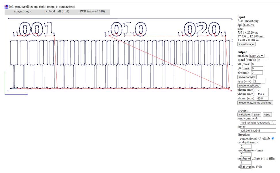
Then save the RML file & import it to SRM-20 for milling. The resalt wasn’t good.
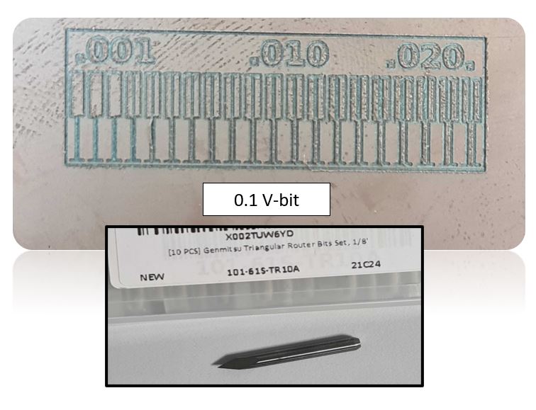
Also I test the lines with 1/64 bit which was neat
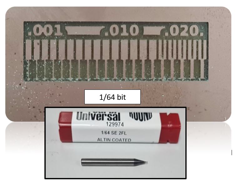
From this experiment I prefer to use 1/64 for milling the PCB