
Mechanical Design &
Machine Design
Group assignment:
- Design a machine that includes mechanism + actuation + automation
- Build the mechanical parts and operate it manually.
- Actuate and automate your machine
- Document the group project
Individual assignment:
Document your individual contribution.
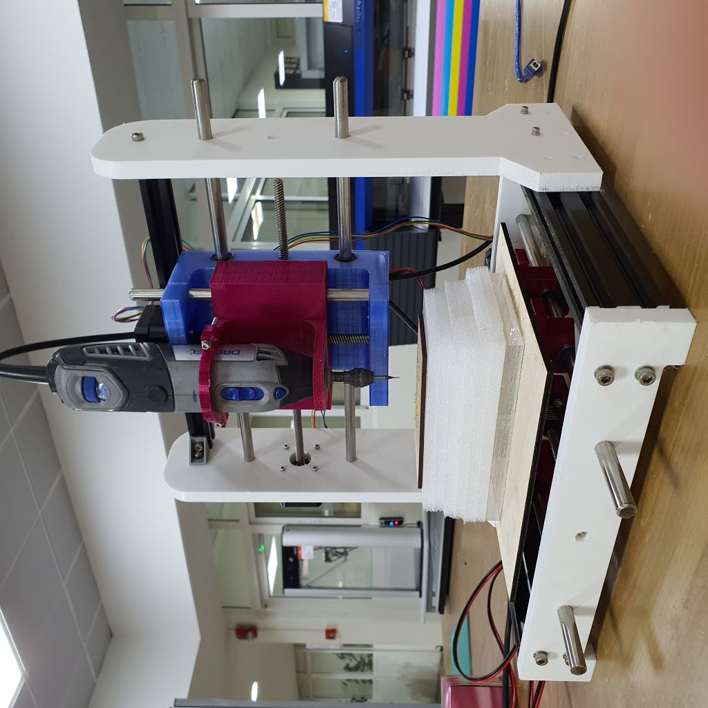
CNC Carving Machine
In this week, my colleagues and I designed and implemented a CNC Carving Machine. Group Page
In this page I will explain my contribution in the project. I contributed in this project by designing the Y-Axis part of the mechanical design.
Y-Axis Mechanical parts:
1. Two side pieces
2. Two 400mm rods
3. One NEMA17 Stepper Motor
4. One single Aluminum Profile
5. 3mm and 5mm Screws
The Y-Axis consists of two side pieces that are connected together with metal rods and a NEMA17 stepper motor placed between the rods. In addition to a single aluminum profile placed on to of the rods for stabilization.
First I designed the side pieces in Fusion360. The folowing image shows the initial design.
Then I did test the design by cutting MDF material in laser cutting machine. After the test I found that the places of screw holes that will be connected with the aluminum profile were not acurate
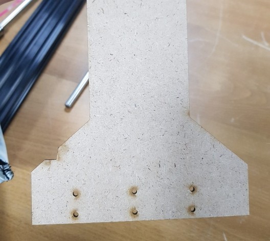
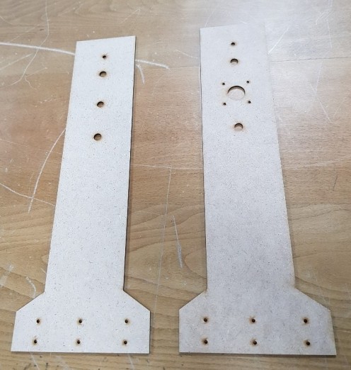
So I measured the width of the aluminum profile and the spaces needed between each hole and I modified the design. Then Mohammed Alshamsi did some modifications to the design by putting the holes of the rods and the motor in the centre of the side piece as shown in the following image. Then I cut it again in the laser machine.
After that, I connected the rods between the side pieces, I inserted the motor with its screw and I screwed the side pieces with the aluminum profile. The design now is fine.
Before cutting the design in ShopBot machine, I decided to reduce the hieght of the design from 400mm to 300mm because the dremel will not be able to reach the board and engrave clearly. Then, Mohammed Alshamsi (project leader) decided to make the length 350mm and he added a fillet to the design.
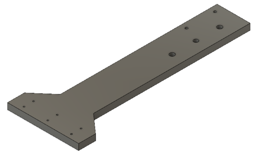
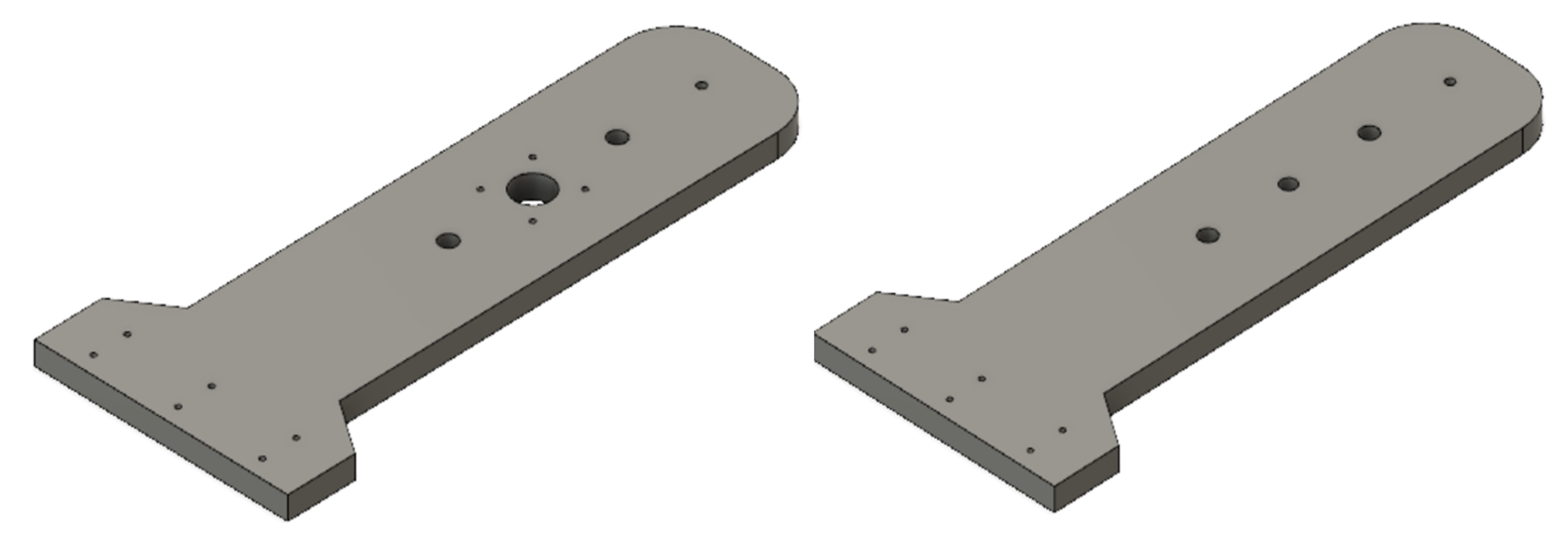
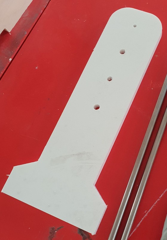
The following image shows the final design of the Y-Axis side pieces in Fusion360.
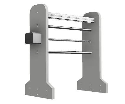
The following image shows the result after assembling the Y-Axis parts in Fusion360.
Now its time to do a test on the material I'm going to use which is the white HDPE plastic.
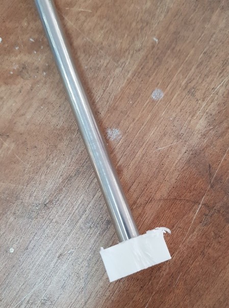
Eng.Moa'ath helped me in this part. First we tried to reduce the diameter of the 10mm holes for the rods to 9mm. We cut a small square for the test by using a 6mm drilling bit as shown in the following image.
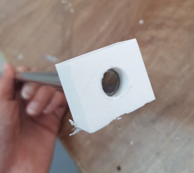
The hole was a little bit small, so I decided to make the holes 9.5mm and I start cutting the Y-Axis side pieces and the frame of the X-Axis.
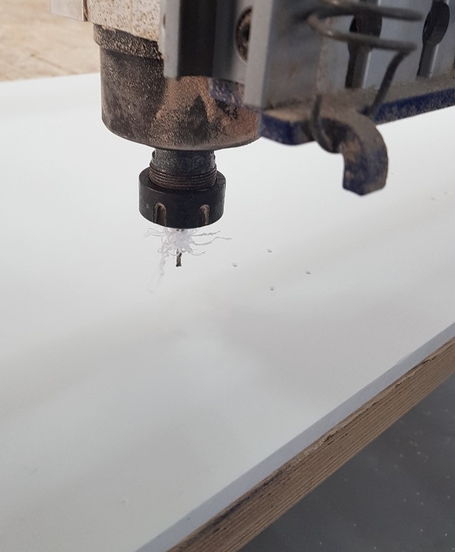
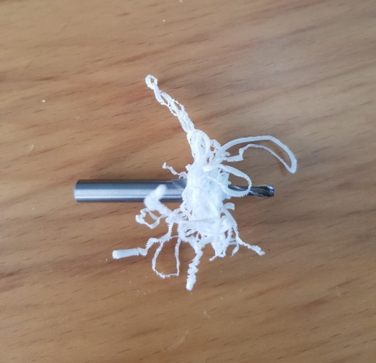
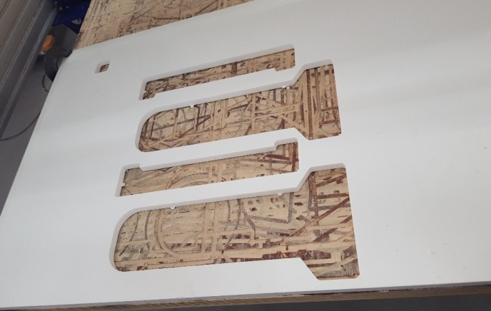
First I used a 3mm drilling bit to drill all holes with 3mm in diameter. Then I stoped the machine and change the bit to 6mm drilling bit to grave all holes with 6mm in diameter and more. Since these bits are used for cutting wood, the plastic was melting and stiking on the bit but the result was good, only a halos appear around the holes as shown in the images.
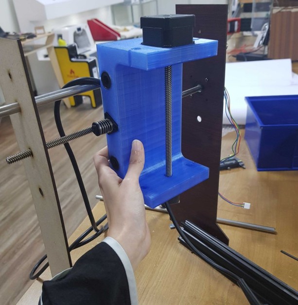
Since we have only 400mm rods and the distance between the sides should be 300mm, I inserted the rods through the sides by using a hammer.
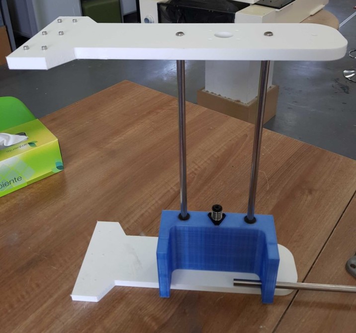
Here the result after inserting the rods and stepper motor in addition to the dremel and its holder.

Design Files list:
| Y-Axis Side with Motor | DXF File | F3D File |
| Y-Axis Side without Motor | DXF File | F3D File |
| NEMA-17 Motor Design | DXF File | F3D File |
Close Project