Week 7
When you can't make the button work and you turn on to your Instructor for a hint

Table of Contents
What a run! This week has been a real ride, since I had no ideas at all about these arguments and I'm not particularly good in programming. I really had to read a lot of stuff in little time but the point was not the reading part as much as the understanding one: it's difficult to make a documentation which can reflect how much you studied and how much work you still have to do, but I'll try to talk about some of the things that helped me go through with this week's assignment and I hope I'll be able to turn back with some updates from time to time!
About ATtiny45
Some Theory about Clocks
AVR Toolchain
About Make and Makefile
Learning about C
Lighting a LED
Using a Button and a LED
Group Assignment
Objectives
- Compare the performance and development workflows for different microcontroller families
- Document your work (in a group or individually)
- Individual assignments:
Read the datasheet for the microcontroller you are programming Program the board you have made to do something, with as many different programming languages and programming environments as possible.
Some Theory and Notes
About Microcontrollers
11th of MarchThis week I'm taking an exam another book to help me, which is "Make: AVR Programming" by Elliot Williams. I find it very useful because it's understandable for those who have no background on the matter and I used it in order to start from the basis and move step by step. It started with some simple questions, such as what is a microcontroller and what can it do.
Microcontrollers are processors that are similar to the CPU that we have in our computers, it reads instructions from a memory space, it sends them to an arithmetic logic unit and stores RAM while the program is running. A nice thing to notice is that the chips in AVR product line include the flash program memory space in kilobytes in the name: so if you have an ATtiny15, or an ATmega328, you have 1KB or 32 KB of space for your code. AVR microprocessors have clocks which run from 1 to 20 megahertz (with external crystal) or more based on what you have. Finally, AVR family of microcontrollers have 8-bit CPUs, which means that most of the math and computation that we will do will involve 8bit or 16bit numbers. Since it is really micro, some of the things that we have on the PC are not present, such as video, sound, hard drives, or operation system - but we do have peripherals, such as specific duties that the singular pins or components have to do.
Let's see this in detail:
- The CPU is the central processing unit and, as we said, is similar to the one that we have in our computers. It reads and processes the mathematical instructions that we give and transforms them in all the input and output actions that he is abilitated to do;
- The Memories are of different types, but the main three are flash (where you store data that won't disappear when the chip loses power and this is called a non-volatile memory), RAM (which is similar to the one that we have in our computer and stores temporary information such as calculations and so on, and it's volatile) and EEPROM (which is more complex and you usually don't have to do with it);
- The Clocks are what give computers and chips a sense of time, pretty much as they do with us. In chips' case there are a lot of different clocks, there is a master clock which runs at 1MHz by default and there are several other tiny clocks for every task of the microcontroller: Input/Output system has one, the analog-to-digital converter has another one, the RAM as well, and so on;
- The Outputs refer to the pins in the AVR chips that can be configured so that they do something and are usable as digital outputs to supply voltage to "speak" with the outside world. The easiest example of this kind of pins is VCC, but also the pin that you connect to talk to the LED to light it on or off is an example;
- The Inputs are those pins that can detect if the voltage applied to that particular pin externally is high or low, and if the voltage is bigger than half of the supply voltage then the chip reads it as a value near to 1 (in a binary system of 0 and 1, there are no "mid points"). This also happens when the AVR detects whether you pressed a button or not: when the button isn't pressed then I learned that the AVR reads the VCC voltage, while when you press it the AVR's pin will be "grounded" - so linked to Ground directly.
Going further in details: ATtiny45
We talked about a lot of things and we took into exam the ATtiny45 Datasheet, moving from there step by step in trying to learn more about how to read the information inside and how pins work. I'm not particularly good at summarizing or explaining stuff but I'll do my best to talk about both what we learned in the lesson and what I red in the book.
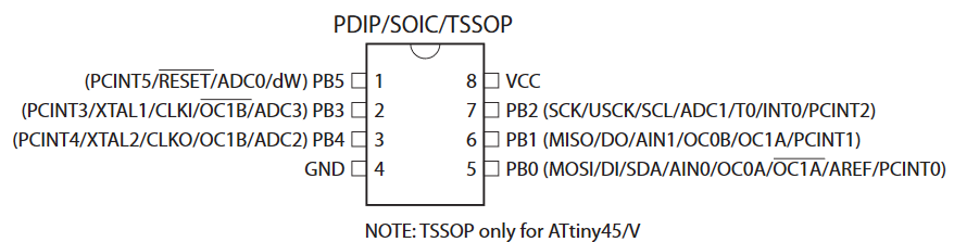
There are different types of microcontrollers, we took into exam this one for our first lesson and we talked about the importance of understanding how microcontrollers work. Each pin on the AVR has its own name and these names can be also spelled using binary codes: we can use these pins for a lot of purposes but they have more or less specific tasks which they can execute. For example, in the past week we had some pins available to connect things up, so you can take a LED and connect it to PB0 for example. Some pins have specific functions, such as VCC or Ground, but an important one is the Reset as well - but I'll turn on this later on.
Based on their function, pins are arranged into banks of pins which correspond to the eight numbers of a byte - so this is why you can also refer to each pin using the eight-bit binary number that each of them has in order to turn it on or off their voltage source. It's not mandatory to have eight pins for each bank, you might also have only four of the same type so you'll have for example a PA bank of the ATtiny44 of eight pins (PA0, PA1, PA2 and so on till PA7) and a PB bank of four (PB0, PB1, PB2 and PB3) - and with the VCC and GND it makes a total of 14 pins. The ATtiny45 instead has only the PB bank. So, as we said, all pins of the AVR can be configured to be either input or output pins, so they can be voltage-sensing components or they can transist switches that will connect the pin through the VCC or GND voltage levels. How you do this is by code, where you have to give instructions and values in order to make the micro-controller do what you want it to do.
Since each slot in the AVR's memory is a byte (and each one is made of eight bits) and each pin is also written as a binary code, we have to learn how to deal with these 0 and 1 sequences to program our microcontroller. Usually when you give the "1" value to a pin then it means its an "output" pin, and when you give it a "0" value it means it is an "input" pin. This is the first of three steps, called Registers that you have to configure - let's have a look.
The three most important hardware registers
Each bank of pins is labeled with a letter (such as P"A", P"B", and so on), let's consider this as an "x" generic letter and see how to deals with registers:
- DDRx - This is a register which stays for Data Direction Register and controls whether a pin is configured for input or output, simply as that. As we said, you can give it a "1" value if it's an output or a "0" value if it's an input pin. The default state for all of the pins is zero, before configuring the pins, so in order to change this you write a one into its slot in the DDR.
- PORTx - When you configured the pins in their input/output declinations you move on to PORT register which gives "power" to the pin, dediding if that pin is set to high or low voltage (VCC or GND). This can effect, for example, the accension or not of a LED.
- PINx - This is where you read the digital voltage values for each pin which is configured as input (which means, since it says "digital values" that is a binary reading so it only reads 1/HIGH or 0/LOW indipendently if you have five volts, 10 volts or so on on that path). This is at a hardware level, because you can't define this register from the software, it's only a register that helps you to read what happens.
Once able to code and to identify the pins, you'll be able to set and modify these register as you think best for the things that you have to do with your AVR. I still don't know how this will turn out in the end, but the lesson that we did was quite clear that these three registers are very, very important in order to get the job done. I'll do some further readings in the book!
Some things to consider: Differences between ATtiny45 and ATtiny44, Clock options
While reading the Make: AVR Programming Book and while looking at my collegue working with a different microcontroller on the PCB and different components on it, I found out that there are clocks inside the microcontrollers as well. They are many and they have multiple purposes, most of them are inside the AVR itself (as suggested at page23 in the Datasheet) and they all activate at a certain time. It may happen that you want to change that time manually using your software, sometimes you can, or you can also toggle its sleep time in order to reduce the consumption of power that it has. Seeing it in detail, the ATTiny45 has some clock source options that you can select with the help of Flash (memory) Fuse bits:
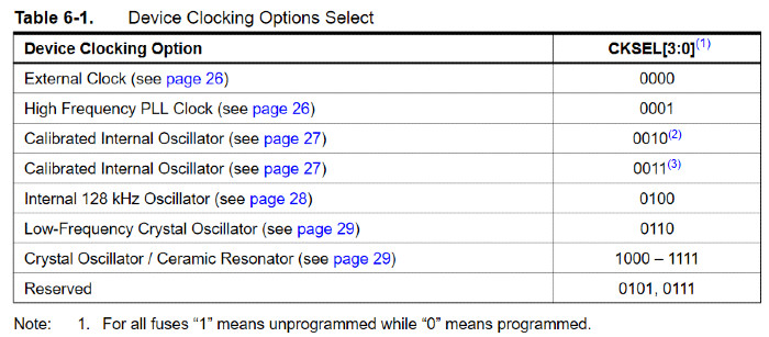
You have multiple choises with these clocks, that might not seem a big deal but it is. One of my collegues had to work on this because of a crystal oscillator that she had on the PCB, which needed to be settend by hand on the configuration of her pins and the setting of the MHz of the circuit. There are a lot of ways to have a clock signal for the microcontroller, and the datasheet of your specific microcontroller might help you with this and it also provides a lot of information about what types you can use and how to implement them. This means that you can tell your microcontroller if you want to use the internal clock or an external one which may be way stronger and useful than the ones that the AVR already has inside. I didn't need with the ATtiny45 to change this, but if you need to you'll have to do it on the Fuse Low byte (Chapter 20 - Memory Programming):
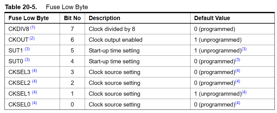
Here it says that happens on every bit (you see them numbered) and if they are programmed or not in terms of "0" and "1" - as we now learned that these systems think in binary code so they only see two values. As you can see, you can Select Clock (CKSEL) based on what you need, on what you have connected on that specific pin and so on, this allows you to do a lot of things if needed. The SUT0 and SUT1 voices, as its clear from the photo, helps you to select the starting time of the clock, while the CKDIV8 voice allows you (if needed) to divide the internal clock in eight little parts.
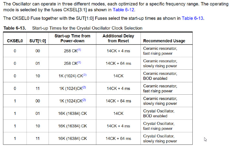
So, when the CPU wakes up (or your computer, for that matter) it goes from power-down to up, and the clock that you selected as source (may this be internal or external) is used to give "a time" to this start-up process: its duty is that of ensuring that the operations of the oscillator become stable by the time the instruction execution starts (the instruction that you give when writing your .c code). If you do have an external clock source, you'll have to set the CKSEL Fuses to "00" - once you've done this, you then can select the start-up times for the external clock as shown here:
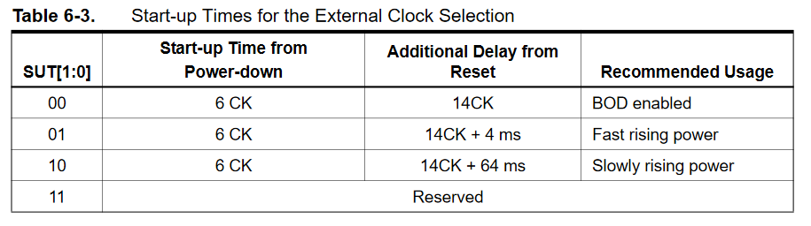
You can find the specific SUT specifics on which one you need based mostly about what are you using as an external clock, because you might have resonators, crystal oscillators, and so on. In order to find your SUT you might want to find a specific section of the datasheet that goes like this:
There are some tools that you might want to use in order to calculate the fuses, you could consider a Calculator, I leave this here in case you might want to use it. I didn't need it, as I said before, because I didn't have to use any external clocks or so on but only my internal one. So I really hope this is useful and clear, and I do hope that there aren't a lot of mistakes, so if you want to be cristal sure I suggest you to check your specific datasheet and have a bit of time to read some of the most important part through.
Connecting the AVR
Steps to Follow
[Week-End]I already covered this in detail in my Week Four Assignment, in the Updates section, if you want to check that out. I hope it might help you, I also listed some of the mistakes and errors that I had, but for a quicker look I'll summarize those steps here to help you get going with the work.
Before starting everything you should have your toolchain going in your computer, may this be Windows or Mac or Linux: I covered the Windows processes on my computer so if you are interested you'll find these specific steps, which are different on the other operating systems. Without further ado, here's in brief what you need to do to prepare for this week's assignment:
1) Download the AVR toolchain for either Windows/Linux/or whatever are you using the moment.
2) Download GNU make, remember here as well where you save and extract the files.
3) Download AVRdude, this will help you do all the things that you need to tell your AVR what to do.
4) After downloading all of this, you have to change your Paths in your Computer. We do this because we want to tell Windows where to locate all the files and tools that you installed, in particular when you type them in the command line. To do so you have to go to Start Menu -> Control Panel -> then head on to System: from the left side you have to choose Advanced System Settings and click on the Environment Variables button.
5) Then you have to download Zadig in order to get the Windows Drivers that you need in order to program your programmer.
6) Now you'll have to check that everything is in order by opening Git Bash and give it a series of comands, let's see them step by step:
- Make
- avr-gcc
- avrdude
7) Download the firmware source code and unzip it, going into the terminal and going with cd inside the directory. Once inside, type make and it will create a file for ATtiny45 which will be called fts_firmware.hex. Hex is the file that "speaks" the language of the chip, you'll need it soon after.
8) If everything is in order, you then move to the last things to consider. Keeping the programmer connected with the computer you run make flash, which I learned will erase the chip and program it with the contents of the .hex file you made before.
As I said before, feel free to roam to week four's assignment in order to see more details about these steps and mistakes that I made and that might turn useful to you as well! I wanted to add this quick map here in order to have a fast and clean view of the steps before moving on to coding, so I cleaned it from most of the screens and details that I left in the extended version on the other week.
Hope this helped!
About Make and Makefile
Since most of the things that we learned this week haven't been particularly easy for me, since I come from a humanistic background, I found a lot of obstacles along the way to get to know the processes behind what we do and why we do them in that specific way. For this very reason I structured this page as a sort of summary of some of the most important things I've studied, hoping they might turn useful for others as well. In particular, after you finish the long run of the installation of the AVR toolchain on Windows, the sad thing is that it isn't over so you still can't throw yourself in the C programming. There are some other steps in the between, one of these is understanding what you have just installed and how it works. Or how you're going to make it work.So, what is "Make" and what is Makefile? Make is a utility that helps you deal with Makefiles, which are files that define a set of tasks that have to be executed. You use make to compile programs from source code, you use it in the Git Bash to transform your .c Code into .hex files that the machine is able to read and execute. You always have to transform .c in .hex, every time you compile with .c you'll need to give a
make command on git bash or your terminal in order to give the machine (your AVR, your PBC) a file it can read. There are a lot of open source projects that use make to compile executable binary files and they can be installed using make install.
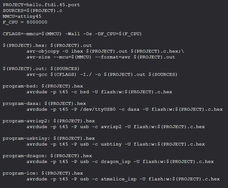
Your Makefile is, as we said, a file with a series of instructions that you give to the program and specifically I downloaded the one that Neil gave us. If you go at the list of microcontrollers of embedded programming week, you'll find a makefile that you can take and use for your work. This is the original file that Neil gave us:
What you need to do with this file is to modify first of all the name of the Project in the name that you gave your file. Mine it's quite desperate, since it's called plshelp and .. no, I'm not calling for aid, I was just overwhelmed about all the things to learn and I wanted to convey my fears. Then you have a series of strings and the ones that start with program- are the ones on which you need to intervene: you can delete all the things that you don't need, in the specifics I deleted everything except the
program-usbtiny since mine is a Usbtiny not an avrisp2, or a dasa and so on. So the final result for me was this one:
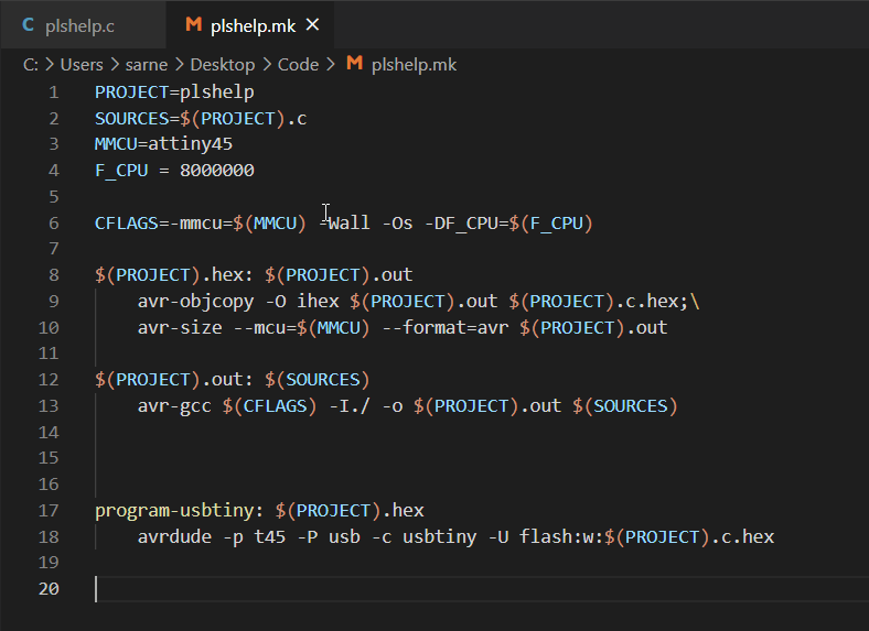
As you can see, there are two files: one is in .c and the other one is .mk which is the extension of Makefile. So once you have these two you can work on the terminal/git bash and work on it, in order to send all the instruction on the AVR. Once you do a
make -f name_of_the_file command, you can move on to the second instruction which is make -f name_of_the_file program-usbtiny:
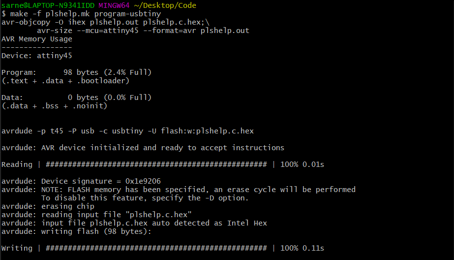
As you can see, it's AVRdude the one responsable for making things work once you give the make commands. I also advise you to check the AVRdude User Manual in order to better comprehend the comands and strings that you can use while working with this toolchain.
Learning more about "C"
Basics
We can program the microcontroller using a variety of languages, we will be using C in laboratory and we did a lesson thursday morning about some of the basis of C language - I'll definetely have to read more about it because I'm not particularly good with this stuff and it easily gets confusing for me. This documentation will have some parts of descoveries and some parts of further reading that I do day by day with the help of the book, trying to be as clear as possible.
We learned that there are a lot of programming languages, that are mainly divided into:
- High Level Languages (most common of which are Python, Javascript and so on) which are closer do natural language and therefore easier to comprehend and write but slower than the other ones;
- Low Level Languages (such as C, C++, and so on) which are closer to the binary language that machines use, so it is more difficult to write with this kind of complex syntax. Low level languages are much faster than the high level ones and it uses less resourses.
Since it's a low level language, C is not particularly easy to understand and write, I myself have a lot of problems in getting to know this language and learning how to use it. We did some sample codes in class in order to learn some of the basic elements of this kind of code, and at first sight it seemed rather "easy" to understand - but it took only a break in the week-end to change my mind and realize that I didn't get it at all. So let's start a bit with the beginning.
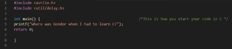
This is an example of C code, a basic string of lines that contain things inside and separate them using different kinds of parenthesis.
- If you look from line 1 and 2 you'll see a comand "#include", this is used to tell the program to include libraries of codes and strings and there are different kinds of these depending of what you are doing. We are using these two, so you always have to start a file remembering to add your libraries.
- Moving on, in line 4 you have "int main" followed by round parenthesis is the main function, which is very important because there always has to be one in your code, this is what the program executes. The green writing that you see in the screen, wrapped between "/*...*/ is a comment, pretty much as those that you might have used in html or css if you used them for your page.
- Going on, "prinft(..)" is also a function which causes the message inside to be displayed on the screen. You can write many of them, do some tests if you like.
The final line, "return 0;" finishes the main function and returns to the value 0.
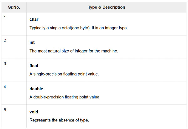
So this is a very basic example on C, the one that we did (more or less) with our Instructor in class, trying to see some other comands such as _delay_ms() or others. One important thing in C are the Variables, which are some "storage areas that our program can manipulate", and I found a beautiful guide on Tutorials Point that I advise you to check. If you're new as I am to these things you might find it easy to follow, just scroll down and click on "Previous" or "Next" to turn back on more basic stuff or go forward to new things. I'll copy here for example (if you don't want to check the link) a quick view from there about the most common variables in C:
All of this had its sense, specially during the lessons before the Weekend - but then the assignment of making a LED blink started to challenge us pretty badly, in particular the one which our Instructor gave us to find a way to light the LED using the Button. I spended all my Weekend trying to figure that out, since in my PBS Schematics you can see that my LED (PB4) and my Switch (PB3) are not connected with each other with copper, so it was a really challenge for me. I didn't manage to do it, opened thousands of links, tried a lot of strings and codes, probably hated everything for a while, so I tried at least to make the LED blink on its own.
The Art of lighting a LED
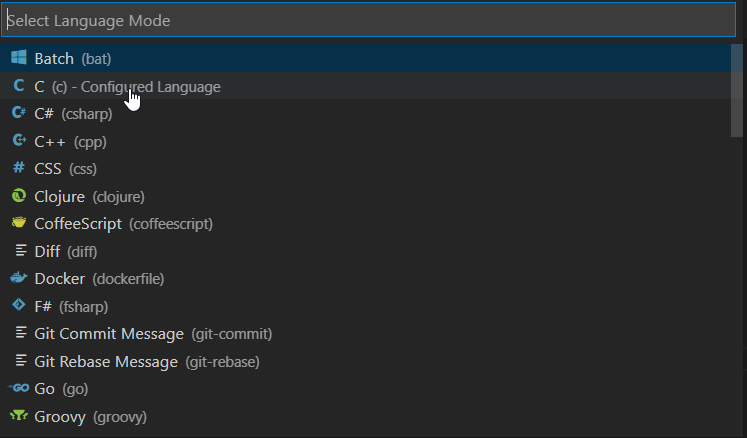
I installed Visual Studio Code for Windows, I have a thing for dark programs because a really hate white screens (.. and my whole documentation is white, I know). Once inside the program, you "Create new File"and you are ready to type whatever you want: Visual Code offers a lot of different languages that you can use, but I descovered that you have to select them because they are not automatic. If you look on the bottom of the program, you'll find a default "Plain text" writing, but if you click on it you'll actually be able to select the language that you need and that you'll be going to use.

At this point, you're quite ready to go - the program is ready as well, all you need to do is start typing what you're going to nead for your programee. I keep the programee connected to the programmer and this last one to the computer while I compile the .c file because I usually test it multiple times in little time so I want to immediately see what is going on with my Led. I make a lot of mistakes in the code and most of the times if I get really frustrated I try changing things little by little and learn by this what went wrong, so I have to keep it always connected so it's easier and faster for me.
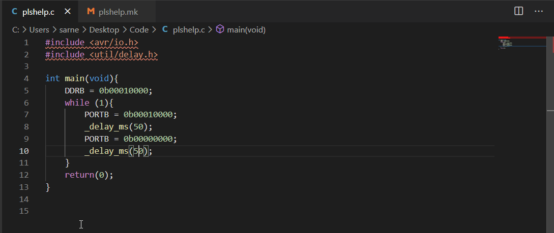
Let's see what I've done with my first code, step by step:
- Line 1 and 2 - As we did before, here you write the lines of code that include the libraries to your file. You can have multiple libraries, depending on what you need.
- Line 4 and 5- Here I opened my Main function, we said that you always need to have one because its what the program will start to execute when it begins to work. You open the curly brackets, then I indicated him the DDRx register of which we talked in the first parts of this page, indicating the "B" bank of pins. I don't have another one with my ATtiny45, but if I were to use another microcontroller I would probably have other banks of pins as well so I'll be needing to specify which one with great attention. I wrote the whole byte, which is 0 (input) on every pin except one which is defined with 1 (output) and it's my LED in PB4.
- Lines from 6 to 11- Then I opened a "while ()" function, here I indicate him the loop that I want to create and let go for an infinite amount of time. To do so, as we said before, you need to indicate him the PORTx register and again select the "B" bank. Once you write your PORTB you then want to think to whom you're directing power: since you want to light the LED and you indicated in the DDRB that the LED (output) is PB4, then you want to give power to that PB4 with your 5 Volts and allow him to send it to the LED in order to turn on. You do so by copying the same byte that you used before and paste it in line 7, then you give the LED a delay time, which is how much it has to wait while lightened before going off. Then you need your led to stay off for a little while, to do so you stop giving him power, so no volts will go towards him, and this is the line 9 - where you can see that all bits are zeros, no power given to none of the pins. At this point, you indicate a delay time for how much time it stays off before starting all over again. At the end, you close the curly brackets.
- Line 12- Having done all of this, you have one other bracket open (the one that goes up until int main void) and before closing this one you type "Return (0); as we said before in the other example. Remember always, as you can see from the screen, to put semicolons after everyline, otherwise that string won't work and avrdude will warn you about this most of the times.
Using a Button and a LED
A lot of mistakes and tries
[15th and 16th of March]Blinking a LED is an easy task, using a button for that is another tale. It seems easy at first but it quickly gets tricky enough to make you waste hours between the book and your notes to figure out the solution, expecially if you don't want to just use Google and copy/paste the code from someone else. I do take a lot of help and inspiration from previous documentations, because some might have answers for problems that I have myself, or I try to understand why someone used the code in they way they did and then trying to work with it. And I tried for this case as well, but it was no great help since you have different pins and components connected with one another that are different from the ones that you find in other documentations, even with a tiny change, so you can't really hope to get the job done by simply looking. The advice here, if I can give any, is to keep reading, keep reading and keep reading.
I did a lot, like a lot of tries with my code in order to understand how to make the LED light up when you press the button. I linked my Schematic up ahead in one of the first sections of this page, or you can see it in the Electronics weeks, and I have a LED and a Button which are one on PB4 and the other one on PB3. They are not connected with one another directly, so what I needed to understand and do was how to make them work together. In order to do so, you have to do the same steps that we did in the example before, such as:
- Define your DDRx Register - This will help you to decide which pins are output and which ones are input, in this particular case I need to have my Button as INPUT, which means 0 on the PB3; and my LED as OUTPUT, which means 1 on the PB4. Why? Because in input you have to be able to read the signal that arrives from the botton (which can either be 0 or 1) and then you have to be able to output power on the pin connected to the LED in order to light it up.
- Decide your PORTx Register- At this point, it should be clear enough that we have to decide in order which of our pins will receive power, and in our case the only pin which needs it is the LED one (PB4).
- Read you PINx Register- In the previous example we didn't use the PINx Register at all, because you can't directly modify it on software or deal with it. As we said, this is a Register which only needs to read what is going on - in our case it reads if our Button (PB3) is pressed (0 value, because if it's pressed then the power goes to ground) or is not pressed (1 value, because the volts remain in the copper line itself and are not used).
In brief, the steps are to: decide which pins you're going to need and if their going to be Input or Output, decide the LED (or more of them) on which you give power and the condition that permits this, which is out button pressed with our finger. Seems easy on paper, but since it's particularly easy to make this work at first sight without knowing a few other things as well then it might get really, really difficult to follow. This is one of the reasons why I firstly failed a lot of time before even getting near the solution, and to do so I had to learn two important things about all of this: Bit Shifting and Bitwise Operators. Let's have a look, hoping I got it right and that it's clear enough.
Bit Shifting
Our Instructor Simone explained us about this and I also went checking on the Make: AVR Programming book in Chapter Four. Bitwise Operations and Bit Shifting help us to deal with one bit in particular without having to mess around with the remaining ones of our byte: we've seen that when you define your DDRx or you do something with a pin, you usually write all the byte number by number, so you affect all the byte even if you only need to work on one bit. We can deal with this by using these two important operations and syntax choices that help us isolating the things that we need without interfering with the other ones. When you define and write a lot of bytes it becomes quickly difficult to keep track and work with all those zeros and ones, so we can act differently by converting them in a simplier syntax.
Bit Shifting is essentially (page 62) the possibility to "write a 1 in bit number x", by rolling the bit that we're interested in into another position either moving to the left or to the right. Bits that fall off in the process simply disappear since they are zeros, while the empty spaces get filled with zeros as well. You have to think that you have a byte with a 1 starting from right, and then you usually decide to move it to the left in the position that you need.
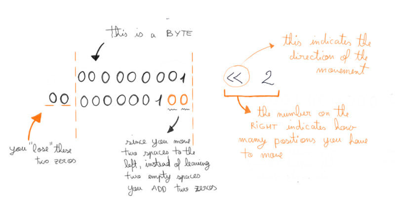
In this way, if you need to isolate PB4 you write to move by four spaces, and so on. It seems a lot tricky at the beginning but it eventually becomes clearer once you take paper and pen and try to visualize it as you try to rappresent the bits that you need. Here is an extract of my final code, for example:
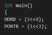
As you might have guess at this point, seeing also my first example up top, I simply declared in my DDRx Register that it has to use the "B" bank and to insert a 1 in position four in order to have my PB4. You can do the same for every pin that you need and as you can see it's way easier than writing by hand the entire byte from time to time. With few things it might work well but when you have a lot of things then it becomes complicating.
Bitwise Operators
In the very same chapter of the book you find the explanation about what bitwise operations are, we did some theory on our whiteboard in the Lab with our Instructor in order to get them right. Bitwise logical operators work on the full byte, not on the single bit. They do logical operations one bit at the time and this makes them so good in manipulating the individual bits inside a register byte. There are four in total, I'll leave here a quick view and explanation of them which I got from the book itself:
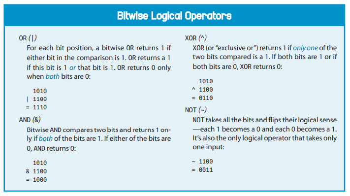
These also take some time to practise and understand them, so personally I found it easier to write them down on my own and trying to get the system rather than simply reading it. But both these two things helped get the final code that allowed me to program my AVR to blink when I pressed the button!
Sometimes it just works, even if you don't get why
Having said that, I finally tried with all this new knowledge to do my .c file with all the instructions to make my LED flash by pushing a button. It worked, but I have to say that I tried so many times that it actually took my entire evening to make it right: its frustrating, but when it works you're quite happy with the result, so much that you don't actually remember anymore why it functions.
So, let's break this code line by line, in order to get it right:
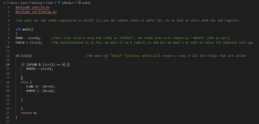
- From line 1 to 11 - As you can see we have the libraries here as usual, and I added a few comments in between to (I hope) help you understand why I wrote something the way I did. You could probably be wondering why I inserted a 1 in my Switch (PORTB line 9) if I said before that I want it to read only, well this is because I want to raise the internal pull-ups and in order to do so I have to give it a 1 if it's first identified as a DDRB=0.
- From line 12 to the end- Here I opened once again a while(1) function and inside it a "if"/"else" one, inside which I created one condition right before the curly brackets in line 14. In this way, if the botton is pressed (so equal to 0) then the program has to give power to the LED and light it up, if it's not than the LED remains off. I also used some bitwise operators as well.
This code is actually a little tricky because, as I said before, you shouldn't be able to deal with PINB Register or write with it, but if I remove it from my code then it stops working. I haven't been able to understand why, but probably I descovered the new frontiers of today electronics. Who knows?
Group Assignment: Try and Compare
Working a bit with Arduino!
[16th of March]Now that I took a (brief) breath from the long journey of getting to know the basic commands of C, I moved on in trying something different and we had the opportunity to try Arduino. It has a welcoming appearance and after trying to get crazy with a little bit of .c code I can see that ANY other language would be easier than this one, so I was quite happy to try to make the LED blink with also this different kind of package.
I learned that when we speak about Arduino we mean a whole package of things going from the language to the software and most of the things that we had to do personally and manually (such as installing the toolchain, avrdude and all that stuff) is done automatically by Arduino in the background and you don't even notive. He deals with most of the things that we had to do with .c to make it work and by doing so it becomes more user-friendly for those who don't want to
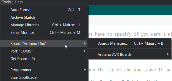
When you work with Arduino you have to tell him which tool are you using, going in "Tools" menu and selecting the "Board" that you're using at the moment. If some boards are not in the libraries of Arduino you can manually download and start using them, or if some boards are a lot similar to others you might also want to try to use a similar one in the software if you're sure it will work when you move to the hardware part. You also might want to look into the Programmer voice in the same menu, this helps if you use a programmer on your own with the programee without using an Arduino Board itself which has both of them integrated. Having said that, I tried to understand how Arduino works and how much its language is different from the .c one I've been using these past days, using the Official Arduino Language Reference and then moved to structure my new code.
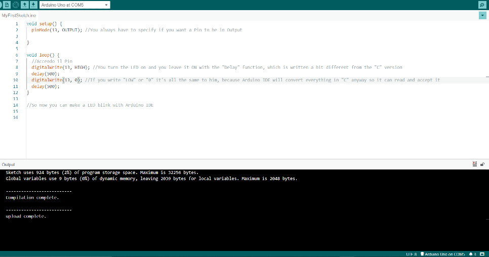
So, as you can see it is "quite similar" but not so much after all. It has two main functions: setup and loop where the first one is executed only once at the start of the program and the second one is what we previously called "while()" in C, so it executes again and again the instructions that it has inside. So, let's have a look:
- First part: Void Setup- Having said what void setup is, let's see after the curly bracktes what we have. The "pinMode" is what we previously configured using the DDRx registers, so pinMode helps us configure the specific pin either as input or an output. Easier, right? You then see a number, "13" is the specific pin on which you operate while "OUTPUT" (in caps) identifies ... what it says, basically, that pin 13 is in output mode. That number is the number of the Pin, Arduino wanted to make things easier so instead of trying to calculate bytes and bits you simply have to google-search your microcontroller and see which Arduino number correspondance you get. To see an example, check this Pinout ATtiny45 Sheet to have an idea, the Arduino number is in blue. In my case, that I had the Led in PB4 I would need to use number 4, and I did - right before switching to another board, which is the one that you see in this screen and uses a 13 number instead.
- Second Part: Void Loop Sorry for the italian part inside, it means "I set on the LED" by using "digitalWrite" indication, which takes the place of what we previously called the PORTx Register. We select the same pin/number as before and give it a HIGH (caps) indicator, but as you can see two rows below if you write "0" it's the same thing, it reasons in 0 and 1 anyway even if it uses fancy words instead of numbers. Again you indicate the delay that you want, note that the syntax is quite different from the one in C, and then you're ready to try!
Another useful thing and tip that our Instructor gave us is to set the Verbose ON (the black screen that you see up in the screen) because it shows you what is going on and errors that might happen.
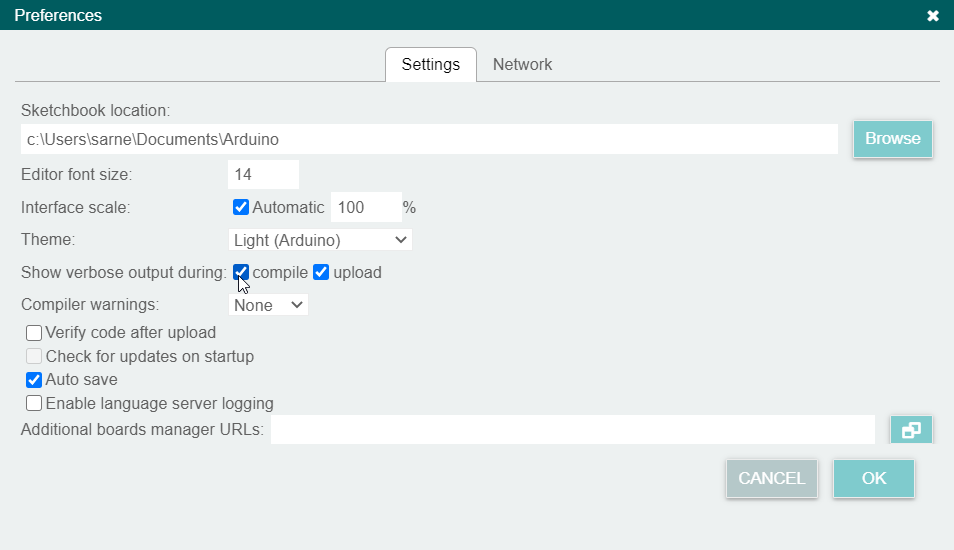
Why you might need this? Because all the processes that before you could watch and read on your terminal or on git bash are now hidden and done by Arduino in the background. If you want to see what it does, the errors that might come up and the processes that it makes in order to make things work then you might want to see them yourself by abilitating these two voices.
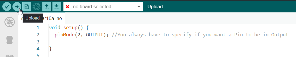
When you're ready to go, you just want to click on the "Upload" button and Arduino will process everything. One important difference with the C code is the fact that even tiny Arduino codes have a weight, which happens to be slightly bigger than the ones that you create with C. Obviously you can write C in Arduino but it has no difference in terms of weight because it will be an arduino file anyway so it will be heavier even if you write in C, so the advice is to use every IDE with the language for which it is structured.
So here's an Arduino test!