Output Devices
Power consumption
In order to measure any power consumption of an electrical device, we need to know the voltage, the current and/or the resistance depending on the equation that you want to use. The three equations are: P=VxI, P=RxI or P=V2/R. Thus, I will use the first equation that in my opinion is the easiest way to calculate it.
I will use a voltage regulator that will provide me with 5V. Then, I will measure the current first and later the voltage to verify that the regulator provides exact 5V. To measure current the multimeter must be placed in series with the gearmotors. The multimeter that I have can measure up to 10 A in direct current. The following diagram depicts the way I connected the regulator, the battery, the multimeter and the motor.
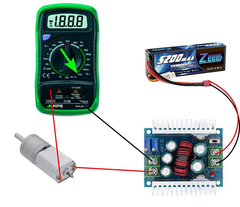
With this connection I got a current consumption of the motor when the motor does not have any load and also when I applied a force to avoid that the shaft moves. I did that to got the maximum power consumption that the motor could have. The folliwng video shows the current measurements of the motors in both cases.
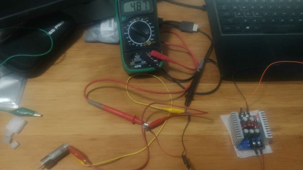
When I finished the measurements of the current I change my connection to a paralled connection which is really easy since is the standard connection. So, I just directly connect the motor to the regulator and later I use my multimeter to measure the received voltage by the motor. The following picture shows the setup and one measurements that I got of the voltage.
Now it is time to calculate the power consumption without load and the power consumption with load. To do that I used the table above to arrange the measured variables and to calculate the power with the equation of P=V x I
| Load | Voltage | Current | Power |
|---|---|---|---|
| No load | 4.87 V | 0.04 A | 0.195 W |
| Load | 4.81 V | 0.08 A | 0.385 W |
it is important to note that the power uses Watts as a unit of measurement and that the power consumption increased to the double when a load was applied to the motor.
Designing a board for output devices
For this week assignment I decided to create a board that is able to control up to 16 servomotors or 12 servomotors and 4 motors. I wanted to create this impressive board because for my final project I need to look for options to control so many devices that the ESP32 by itself cannot control along the input devices and the communication protocols. Thus, I started the creation process by selecting the devices that can help me to create this. After searching for options, I found out that there is one device widely used to control up to 16 servomotors which is the PCA9685. Regarding the motor driver, I wanted to limit the current limit up to 1.5A for continuous current and I found the DRV8833 which is a dual H-bridge Motor Drive that can handle up to two motors with 1.5A RMS and 2A peak per bridge.
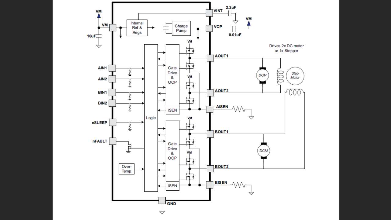
The idea of this board is that the servomotors will be controlled trough I2C from the main board while the dual bridges will be controlled through the main board and the PCA9685. The main board sends signals to control the direction of the motors while the PCA9685 sends PWM signals to control the speed of the motors. Then, I analized the functional block diagram proposed in the datasheet of the DRV8833 where they showed the following connection diagram.
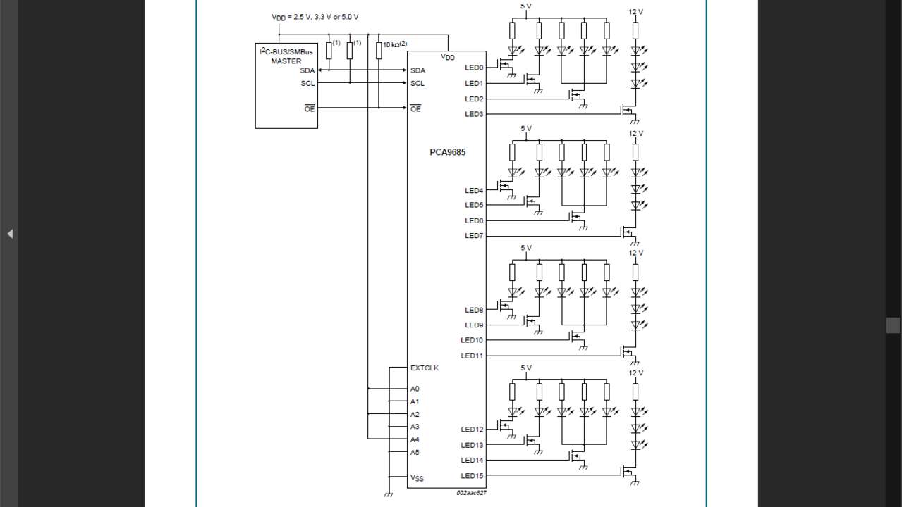
Regarding the PCA9685, the datasheet depicts the following diagram. It is important to note that they application they showed is to turn on LED and that is why they use MOSFET to turn on the LED's. When we want to use servomotors we do not need to use the MOSFET because every servomotors just need the PWM signal, 5V and GND,
Now it is time to start my own schematics to create my output board. For more detail about the design process of PCB you can go to my Electronic Design week. At the end the connection was not so hard since I already had the proposed connection from the datasheets. The most difficult part was to calculate the resistance that the dual bridges needs in case I want to limit the current. So, the datasheet says that the required resistance to limit the current is equal to 0.2 V divided by the current limit. In my case I set the current limit at 1.2A which gives a result of 0.16 Ohms. After that calculation everything else was to follow the diagram in the datasheets. The figure above shows the final schematics for my great output board.
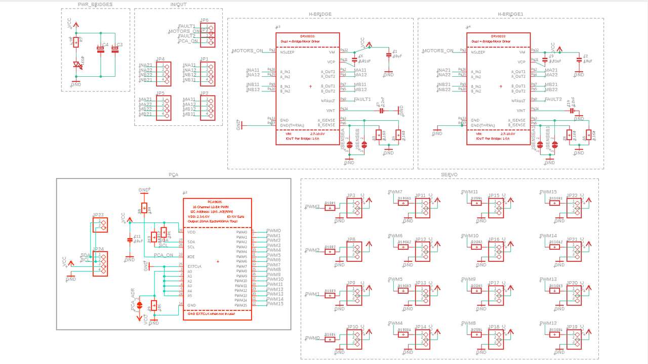
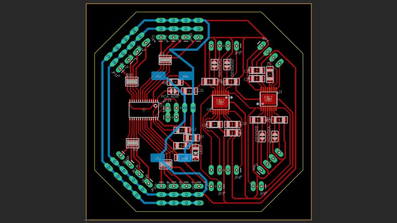
Before I started moving the components to arrange them and connect them. I imported the outline of my main board to fit everything in the same space. In case you want to do it you just need to select the outline, go to export->dxf and save it where you want it. Later you can go to the other fie where you want to bring the outline go to import->dxf and select the created file. After those steps were done you can move it where you want. So, my final boad is illustrated in the next picture.
When the board was done, I saved the top and bottom traces because it is a double-sided board and the outline of the board. The following pictures represent the traces of the board where it is important to note that the bottom traces were mirrored horizontally to be able to machine the bottom layer since the board must be flipped.
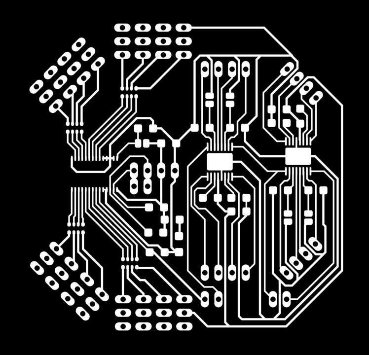
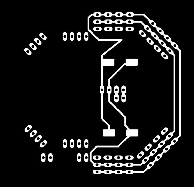
Another important point is that the ground and voltage signal have a bigger thickness to help in the dissipation process since the three devices can have a very high current consumption.
Creating the board
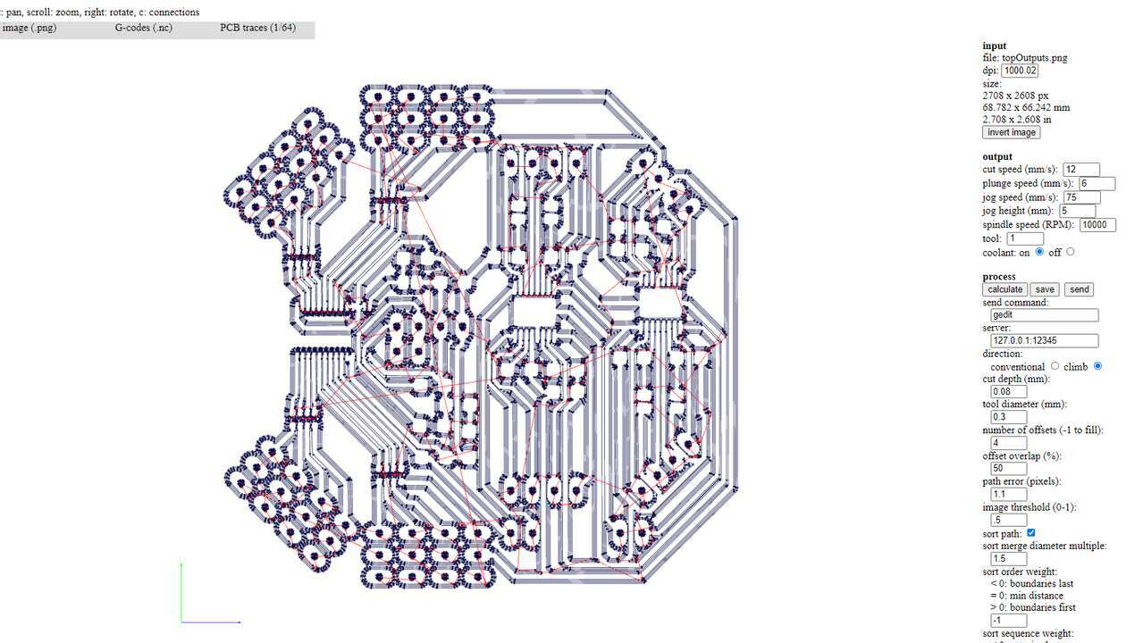
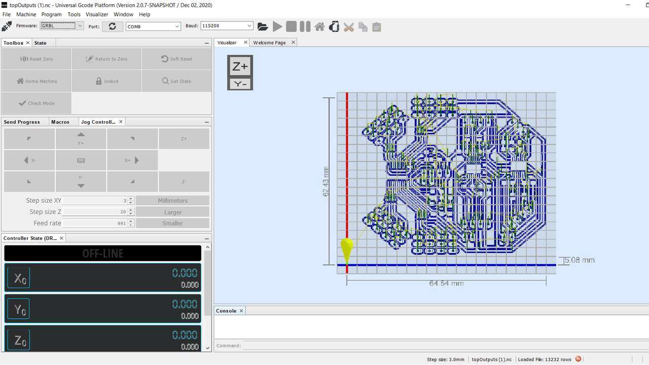
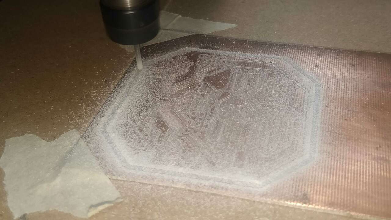
In order to machine the board, I used fabmodules to generate the G-code and I also used UGS to send the G-code to my Mini Router CNC 3018 PRO. For more detail about the machining process of PCB you can go to my Electronic Production week. The following pictures shows the top path generated in Fabmodules and the same path in UGS. When I was generating the path, I realized that the distance between pins of the DRV are too small that the 0.4 mm of diameter did not fit into the pins and I had to change up to 0.3 mm diameter in order to fit correctly. I am a little afraid that the pins will not come out well since they are too small and it is possible that the endmill will break them.
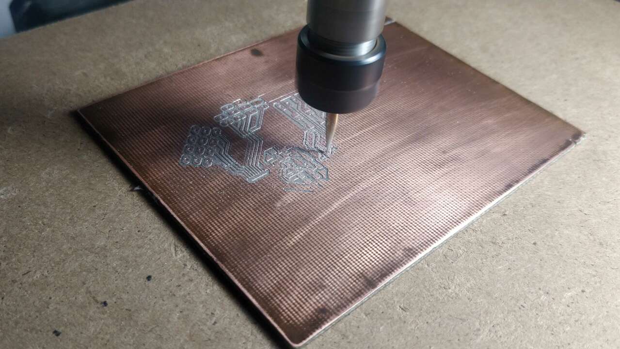
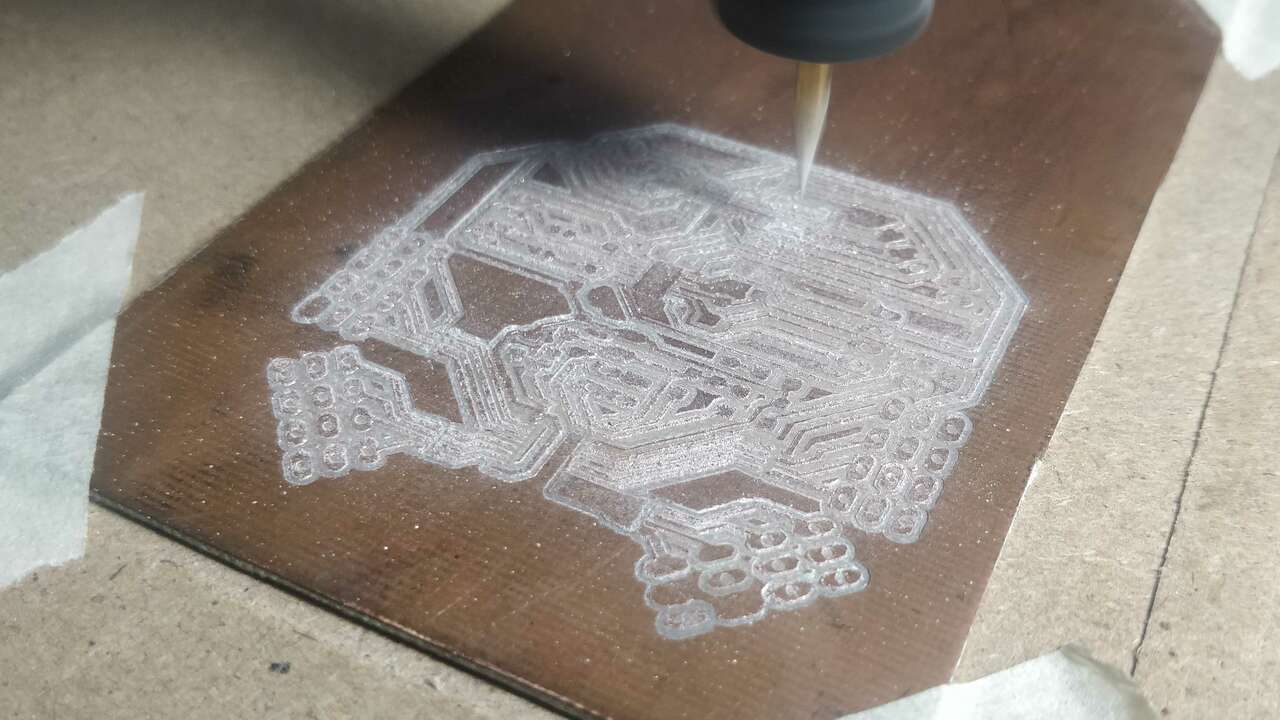
The three pictures above show the machinning process of the board. And I think they looked good :D.
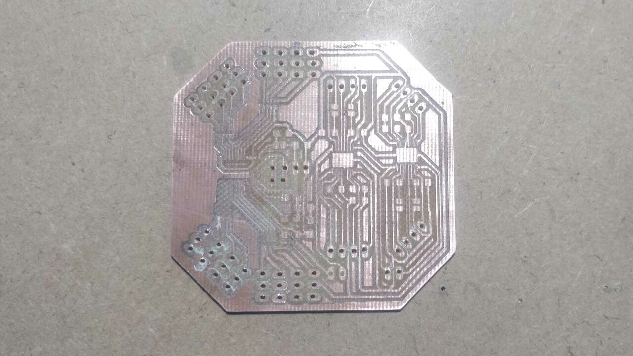
Once I finished both sides, I clean a little bit the board and I also remove some parts where the endmill did not fit. I think the board looks pretty good.
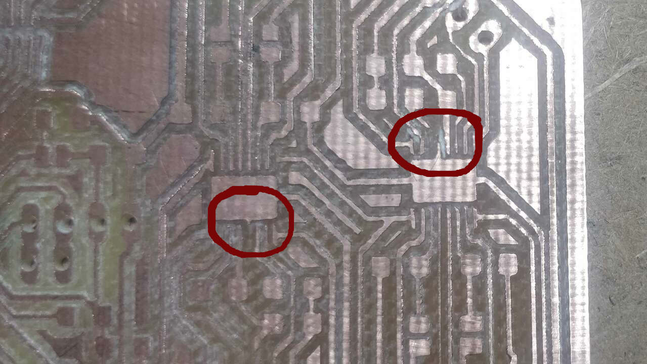
Before I started with the soldering process, I verified that all the paths and connectors were in the proper position and that there is continuity between signals. Nevertheless, I realized that they are two pins that were broken or removed by the V-endmill. In one H-bridge the broken pin was the internal supply bypass which according to the datasheet is needed since it has a capacitor to mantain low power supply impedance at the point of load. Thus, I cannot use that part of the board beacuse it will not work properly. The pins that was broken in the other H-bridge was GND and the biggest problem is that there is no other pin with GND and it will not work without grond. The following picture illustrates the broken paths.
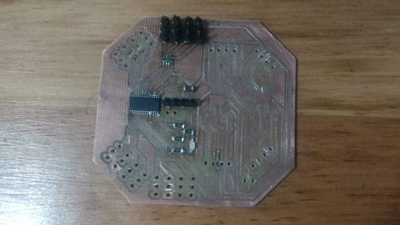
Therefore, I decided to not use the H-bridges part and just connect a required components of the PCA9685 and four outputs for four servomotos to accomplish the goal of this week and not waste material. I took this decision since it is really difficult to buy new devices during pandemy and I will remake the board for my final project with all the components. So, the following table shows all the components that the whole board requires but like I said previously, I just connect the neccesary ones.
| Quantity | Component | Model |
|---|---|---|
| 1 | PWM generator | PCA |
| 2 | Motor driver | DRV8833 |
| 3 | Ceramic Capacitor | 10uF |
| 2 | Ceramic Capacitor | 2.2nF |
| 2 | Ceramic Capacitor | 0.01uF |
| 1 | Electrolitic Capacitor | 2200 uF |
| 4 | Resistor | 10k Ohm |
| 1 | Resistor | 4.7k Ohm |
| 4 | Resistor | 0.16 Ohm |
| 4 | Four resistor pack | 220 Ohm |
| 1 | LED | 1206 |
| 5 | Pin header | 1x4 trough hole |
| 16 | Pin header | 1x3 trough hole |
| 3 | Pin connector | 1x2 trough hole |
The neccesary components were the resistors for the I2C communication, the resitor to enable the PCA, the resistor and the LED to verify the power supply, the capacitor for the input power, one arrange of resistor to enable four servomotors, the PCA9685 for sure and the pin header for the power supply, the I2C communication and the servomotors. After soldering these components, I got the following board that will be only able to control up to four servomotors.
Programming the board
As a first test, I verified that the I2C communication was correct using a code that I previously developed with the only difference that I changed the speed of the serial communication since the ESP communicates at 115200 baud. The following pictures shows the code and the setup to test the I2C communication.
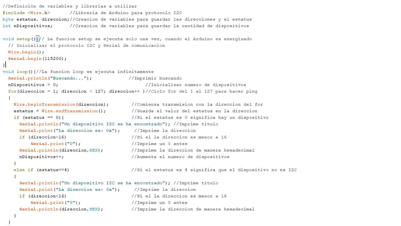
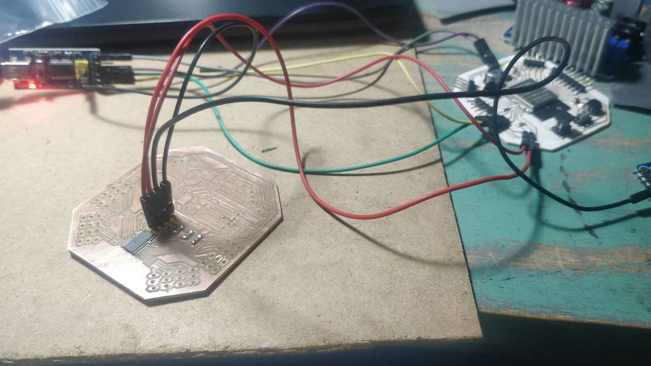
Also a video that shows that the I2C communication is working properly is shown below.
Once the communication was working as expected, I proceed to create a code to move three servomotors. So, I found a code that is doing what I wanted in the following tutorial. I loved the tutorial because they explained you every part of the code and so you can know what it does. Nevertheless, I had to import a library from Adafruit which must be installed manually with a zip file. So, I went to the repository of the library here and I went to Arduino to Sketch-> Include library-> Add .ZIP library and searched for the ZIP file from Github. After that process was done I was able to see the library called "Adafruit PWM Servo Driver".
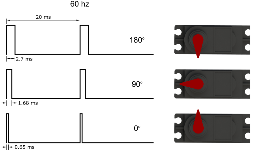
I will be using the servomotor MG90S which are tiny servomotor with metal gears to increase the required torque. A servomotor like this requires a PWM at a frequency of 60 Hz, which means that a pulse occurs every 16 ms. The servomotor reads the PWM and moves the shaft to the correct angular position. Normally, a pulse width of 1 ms duration moves the shaft to 0°, and a pulse of 2 ms duration moves it to 180°. However, the pulse width can vary in order to reach 180°, as is the case for the MG90S. After testing the servomotor with different pulse widths, it was found that 130(0.65ms) and 663(2.7ms) for the duty cycle are the minimum and maximum pulse durations to rotate from 0° to 180°. The following picture shows a diagram with these results.
Thus, I changed the pulse width in the code, the quantity of servomotor that will be used and I did the required connection. The final code and the setup and are shown below:
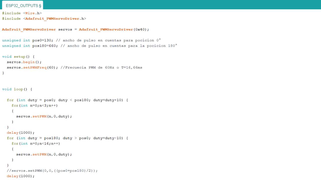
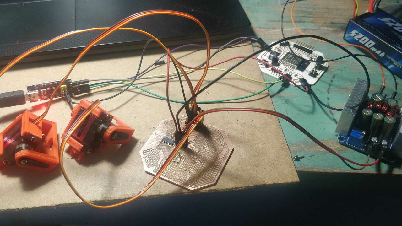
Finally, a video that shows how the created board with the PCA9685 controls three servomotors through I2C communication from a ESP32 is shown below. The servomotors that I used for the practice have 3d printing holder that I will be using for my final project.
Files created
Useful Resources