Electronics Production
PCB production
There are many production processes to create a Printed Circuit Board (PCB), such as etching, milling and laser cutting. However, all of them execute a subtractive process because they need to remove the excess of cooper from a copper clad board. The left copper on the board is called path and they interconnect the electrical components which are placed and soldered on the board with a soldering wire.
No matter the production process, there are four specific steps to manufacture a PCB,
- Design: This step is usually made with a computational software that allow us to design and simulate the electric circuit.
- Production: This process eliminates the copper excess from the board. The milling process removes the copper excess with an endmill while the etching process removes the copeer excess with an acid.
- Assembling: During the assembling stage, we need to gather all the electronical components and solder them into the PCB with woldering wire. There are many things to consider such as, component temperature, type of soldering wire, tools to solder correctly and fume extraction.
- Verification: After the assembling has been executed, we need to verify that the PCB is doing what it is suppossed to do.
Testing the Mini Router CNC 3018 PRO
Since, I am the only one that is taking FabAcademy in FabLab Puebla that is in Mexico, I will document all the group assignment in my own webpage. The milling machine that I used to create my PCB's is a Mini Router CNC 3018 from Gadget Bro. It is a fantastic machine that can handle high precision which is really important to create good PCB's. Since, it is a miiling machine it works exactly as a big CNC router. Thus, it has three axes of fredowm, X, Y, and Z; where each axis is moved by a stepper motor. It also has a spindle to make rotate an endmill and cut the material. The following picture shows the machine and after the image, the machine specifications are depicted.
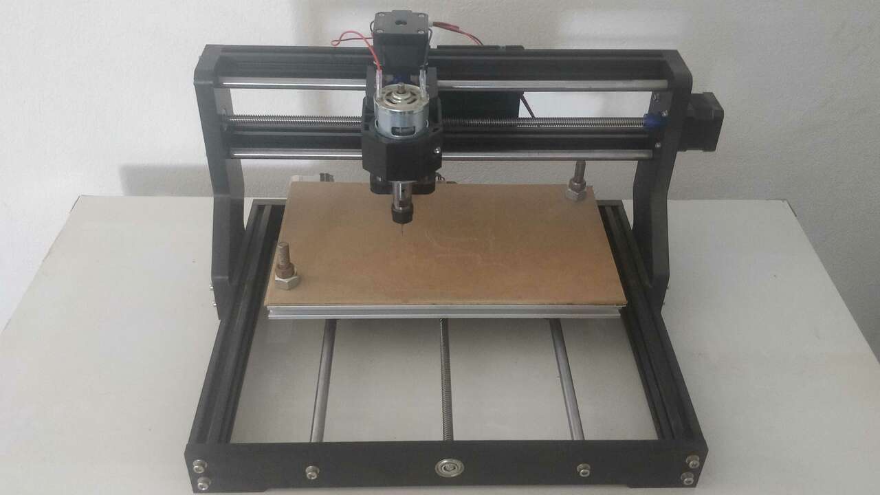
Its main specifications are:
- Working area: 300 x 180 x 45 mm
- Spindle: 80 w at 7000 rpm
- Collet: ER11
- Power supply: 24V 5.6 A
- Software: GRBL
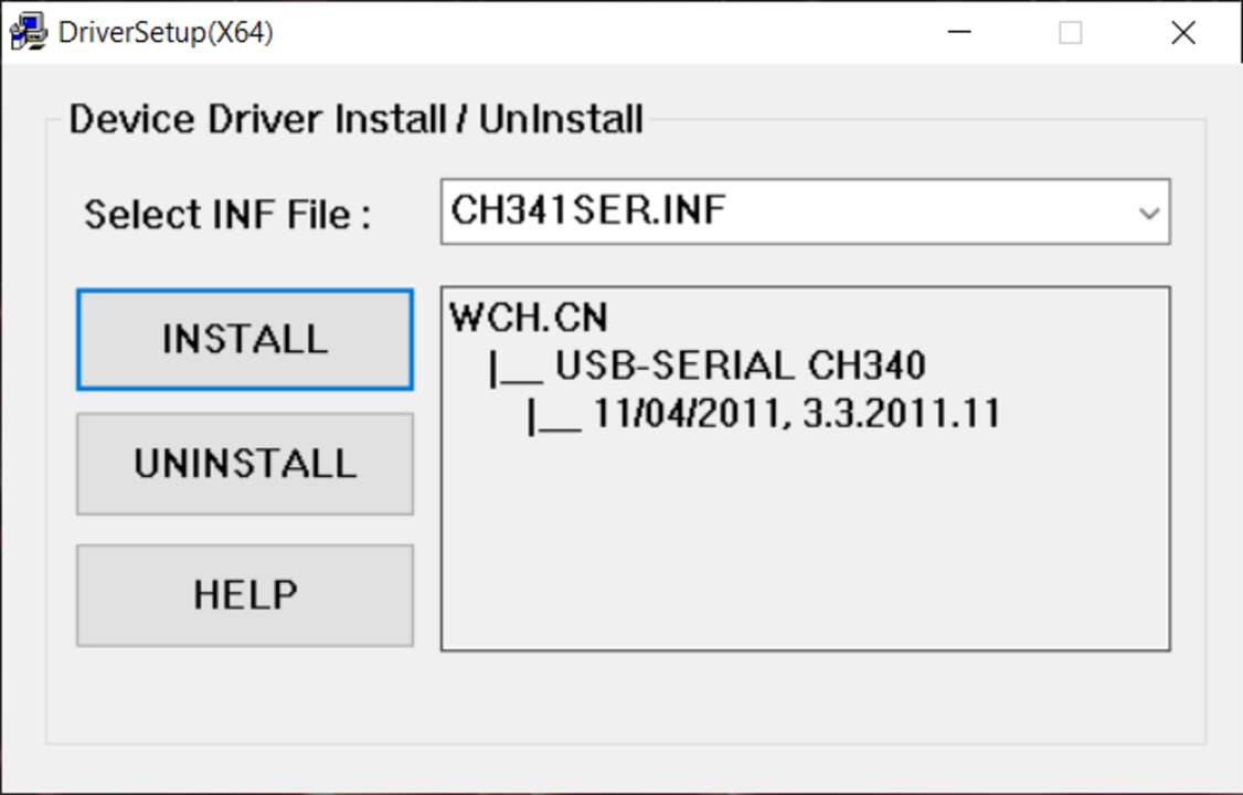
Since FabLab Puebla closed its doors by the pandemy, my instructors lent me the machine that I previously presented. Nevertheless, they told me that the machine has not been used in almost a year and they were not sure if the machine still works. Therefore, the first thing that I did to test the machine was to connect the machine and see if the CNC board works (Well that at least the led are on). When I saw that the machine was turning on, I proceed to install the drivers to detect the CNC's board. This driver is the CH34SER and it can be download from here, the installation process is relatively easy, you just need to download the files and inside the folder CH341SER the SETUP.exe file can be initialized with double click. After the programs opens, you have to click on install and the driver will be installed automatically.
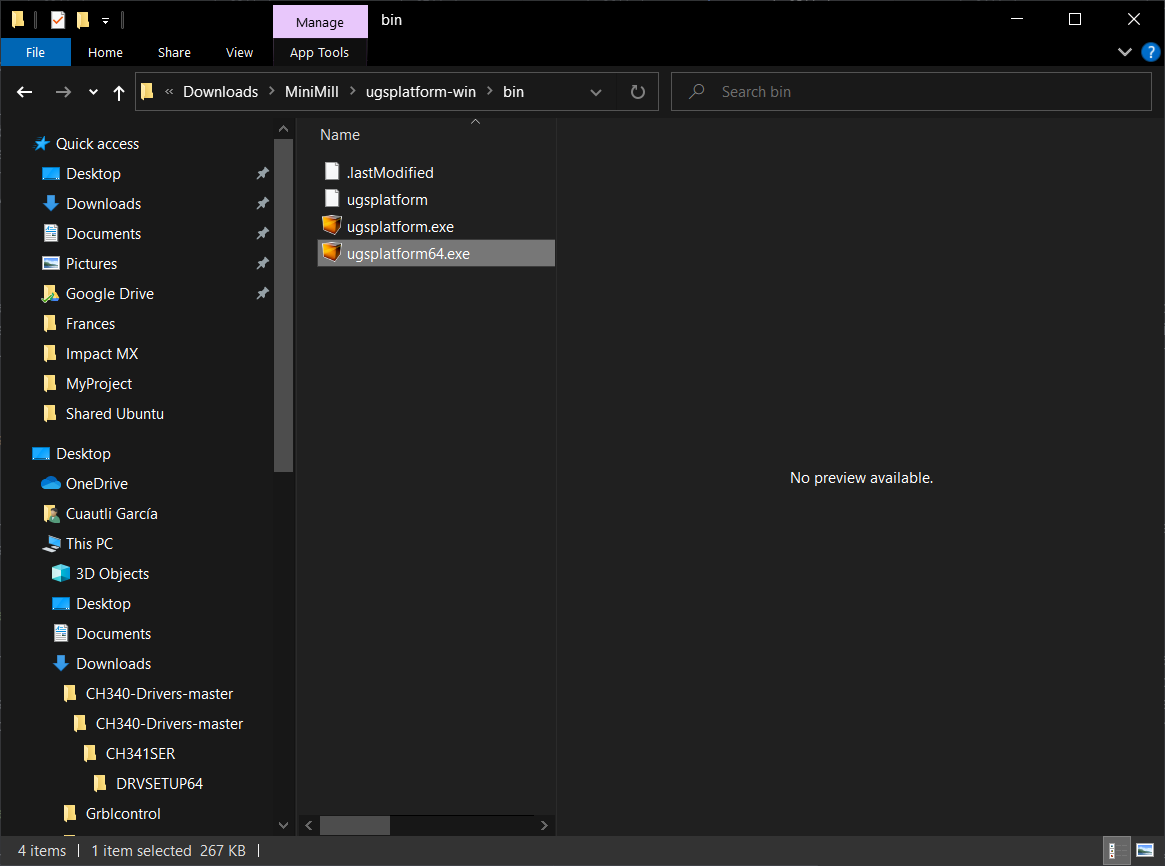
Once the driver was installed, it is neccesarry to install the software that we will use. I chose the UGS platform which is really intuitive and I loved it. Thus, you can dowload the software from here and you just need to go to the bin folder and open the .exe file depending on your system version as it is shown below.
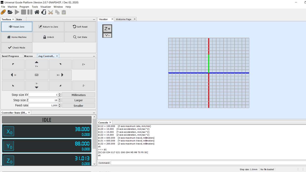
- Select GRBL as firmware
- Select the right COM (If you do not know the COM, you can go to device manager and look for the COM with the name of CH341)
- Set the transmition speed at 115200 baud
- Finally, you have to click the button on the top-left corner that look like a plug connector
If the connection was successful, you must now see the following screen. In case you want to move the machine, in the middle-left part of the software, there is a section called jog control. The button in there with the arrow and the axis name shows you the direction were the machin must move and down these buttons, you can select the step size for the X-Y axes and for the Z axis.
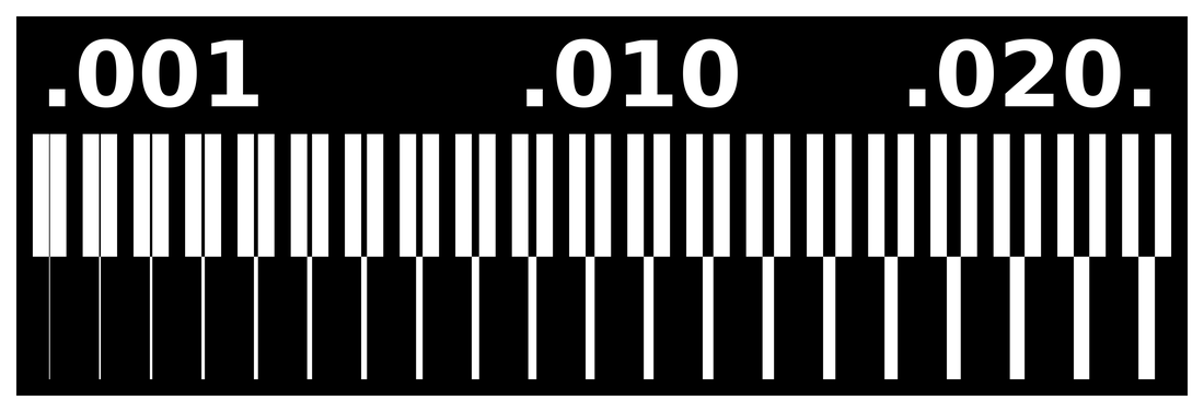
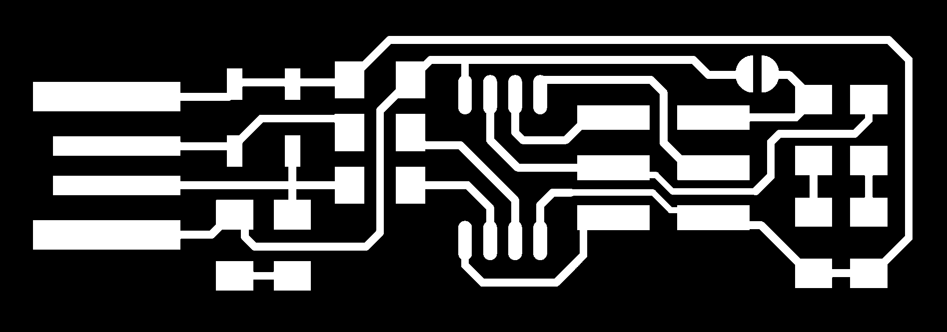
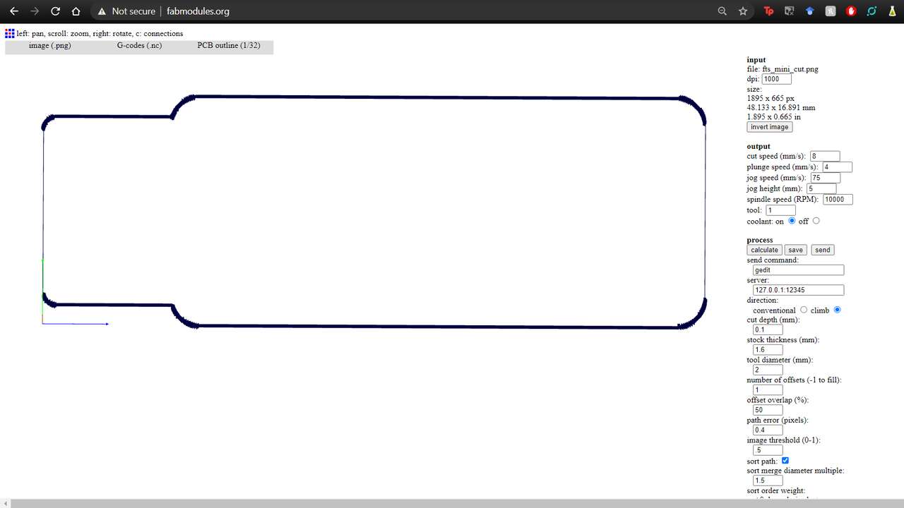
The next step is to create the gcode file with the engraving instructions, because first we engrave and second we cut the board. The board that we are going to engrave is the following:
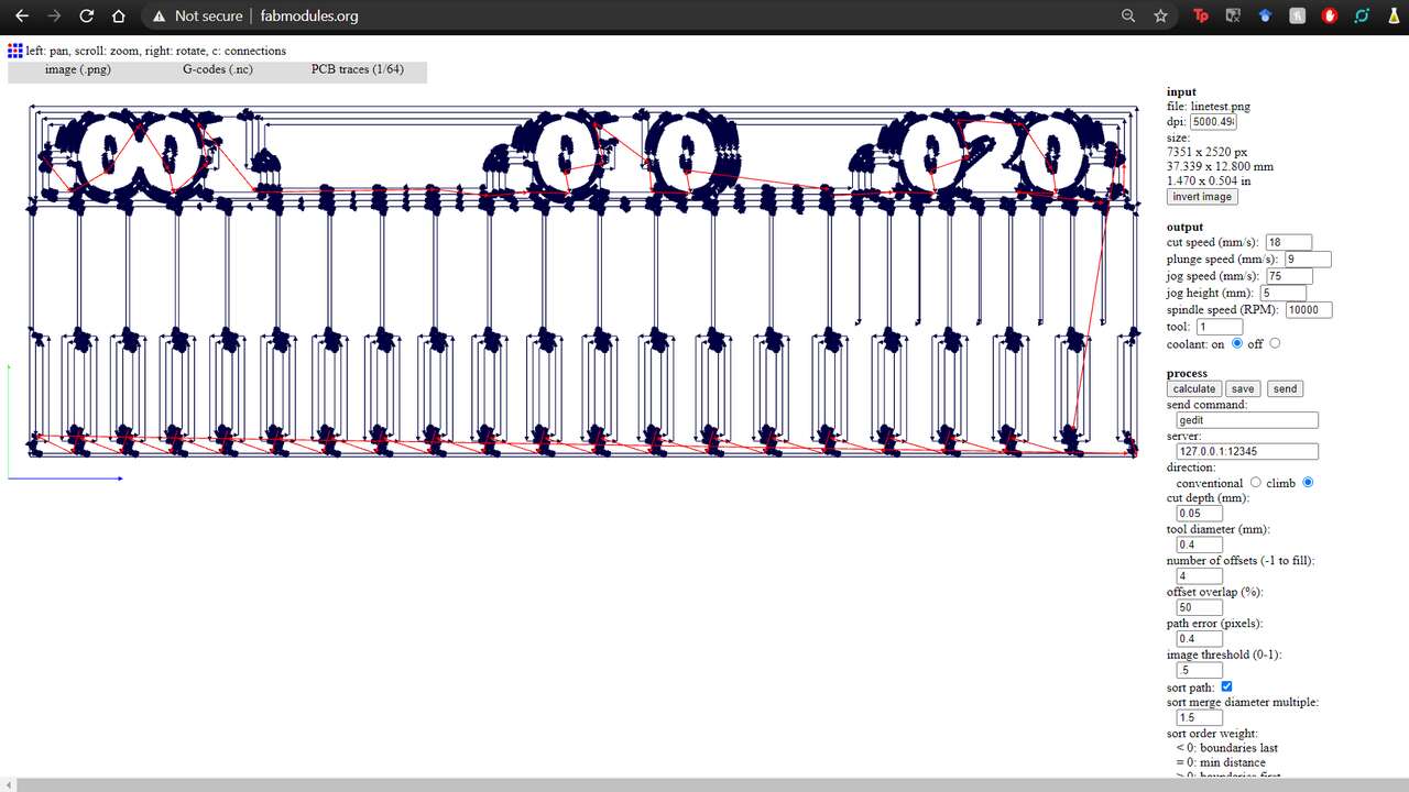
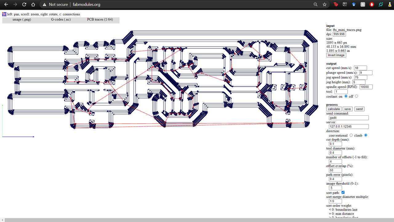
Thus, we open fab modules and we use the previous png that was given by Neil. After the png image was chosen, we need to select "G-code (.nc)" and "PCB traces (1/64)". These setting tells to fabmodules that we want a universal g-code and that we want to engrave the traces of the PCB. For the feedrate we set the cut speed at 18 mm/s, the plunge speed at half of the cutting speed. The jog speed, the jog height and the spindle speed, we let them as they are. For the next setting we use, 0.08 mm for the cut depth, 0.4 mm for the tool diameter, 4 for the number of offsets and the path error is 0.4 pixels. The picture aboe shows the setting and the engraving simulation in fabmodules
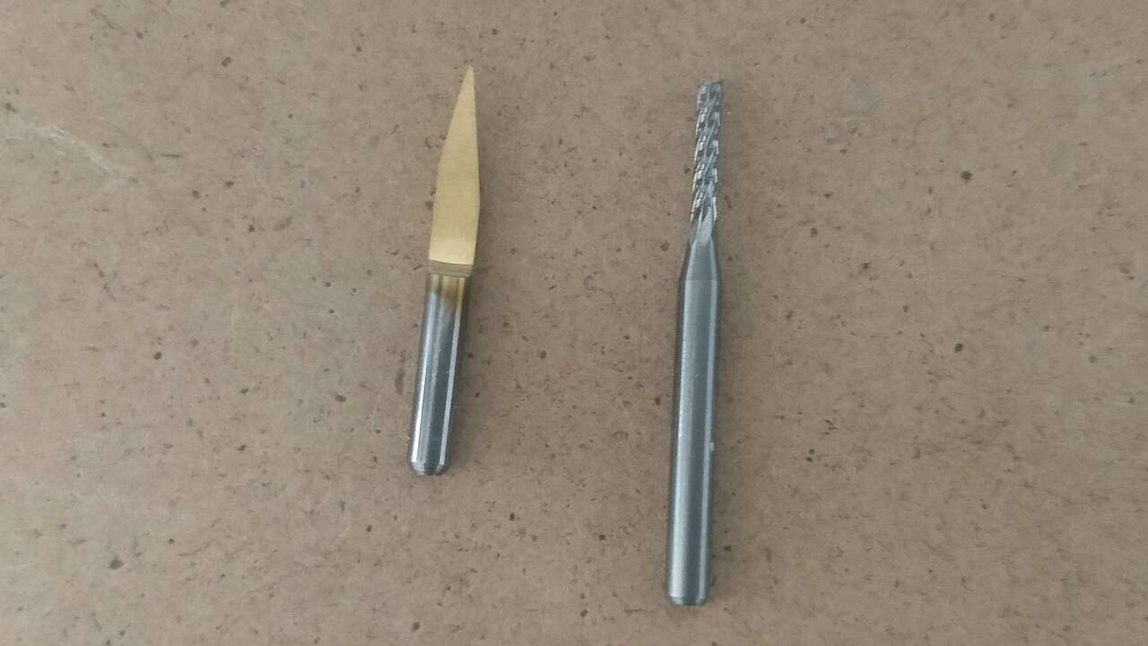
When the simulation was done, I saved the gcode just by clicking on the save button. The time to set the machine and the tools has arrive and we need to know what endmill we are going to use. For the engraving we will use a 20 degree 'V' endmill and for the cut the outline we will use a 2 mm straight enmill with two flutes. The next picture shows both endmill
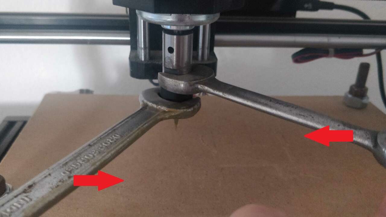
So, before turn on the machine. I put the V endmill in the collet and I use both keys to tighten the spindle nut as the following picture shows.
Once the tool was tightenned, I proceed to do the following steps to send a test on the air:
- Hold the pcb to the MDF plate with double sided tape
- Plug the power supply and the usb cable
- Turn on the machine with the switch that is on the main board
- Connect the computer to the machine following the steps that were shown before for the software verification
- Move the spindle with jog control to the bottom-left corner of the board
- Click the reset Zero
- Move the Z axis just until the tip of the endmill touches the top surface of the board
- Click Z0 on the bottom-left corner of the panel
- Load the file created in fabmodules by clicking the folder and selecting the gcode
- Finally, click the play button and monitor the machine to see that everything is working as planned
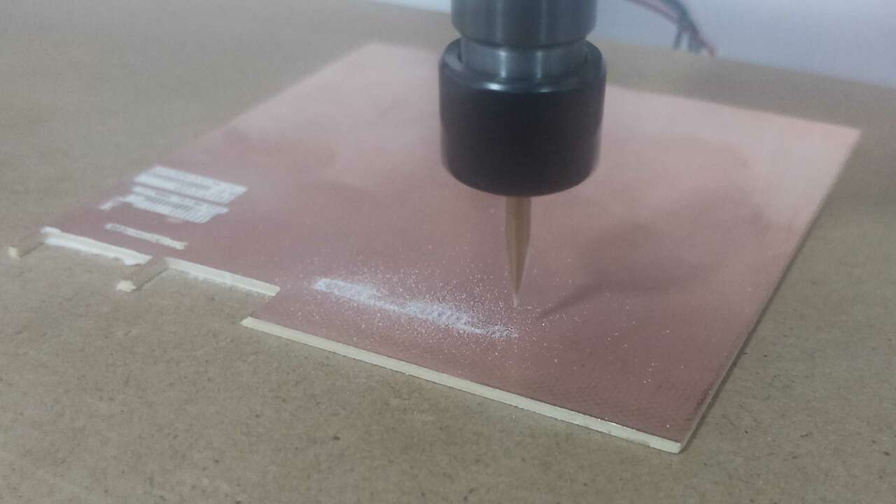
Something important to note is that the first time I run the program on the air and I did not set the Z0 with the material. This step was done just to verify that the machine was working correctly because it has been a year without using it. The following video shows this first test and very sadly I realized that the machine was jumping steps on the z-axis and I was really sad.
Since the machine was not working I did the following steps to fix it
- I did a visual inspection to the machine and everything was right
- I manually move the three axes and everything was right
- I disconnected all the motors and components from the board and I did another visual inspection over the board, here I found the first problem: one driver was burnt
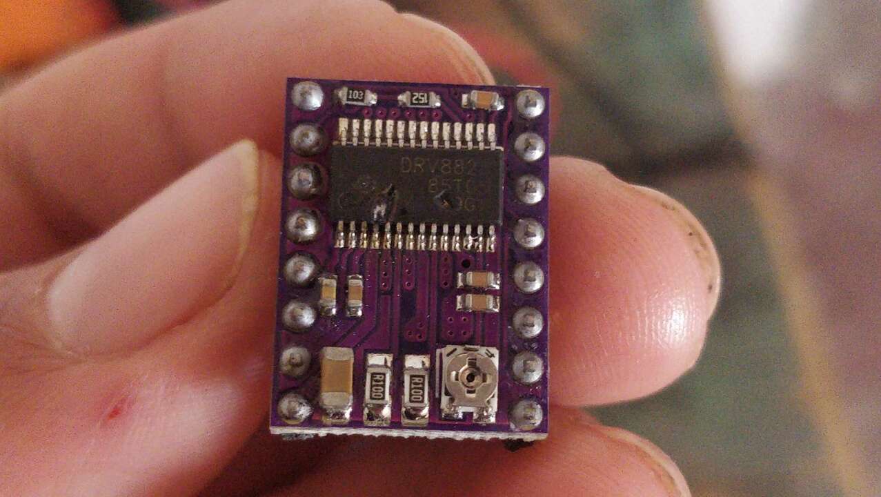
So, I ordered two new drv and wait almost a week for them to arrive. When they were here, I changed the driver and send the same file on the air to see if everything was right. Unfortunately the machine kept jumping steps but now in a different axis which was nor logic because it was not doing that before. Thus, I decided to switch driver between them and see if there is a wrong driver that was causing this. Nevertheless, I did not find a clear pattern to know if a driver was burnt or there had a bad parameter. Then, I searched the datasheet of the driver DRV8823 to see if there is something important to know about it. Surprisingly, I did find something important and it is that the drivers have a current control. Then, I searched tutorial that talk about the current control to see if motor could jumps steps if the current was not correctly set and I found this tutorial that explains how to make the initial setup of the drivers and also explains that if the current is higher than what they must be, it is possible that the motor misses steps.
Knowing that this could be the possible error since the beginning, first I searched the current of the stepper motor that the machine has and I found out that the motor consumes 1.3 A. This tutorial is really good and it shows the following two pictures which display the electrical diagram to adjust the current of the driver and they also show where to measure the reference voltage to know the set current.
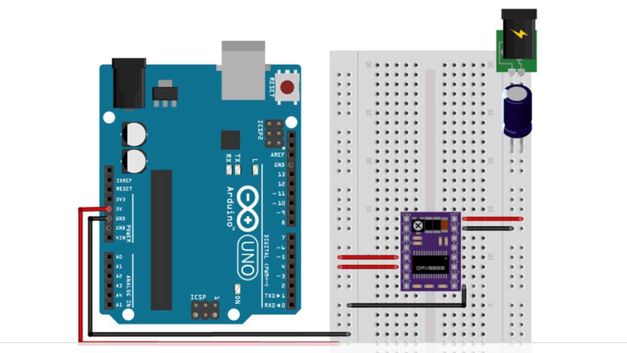
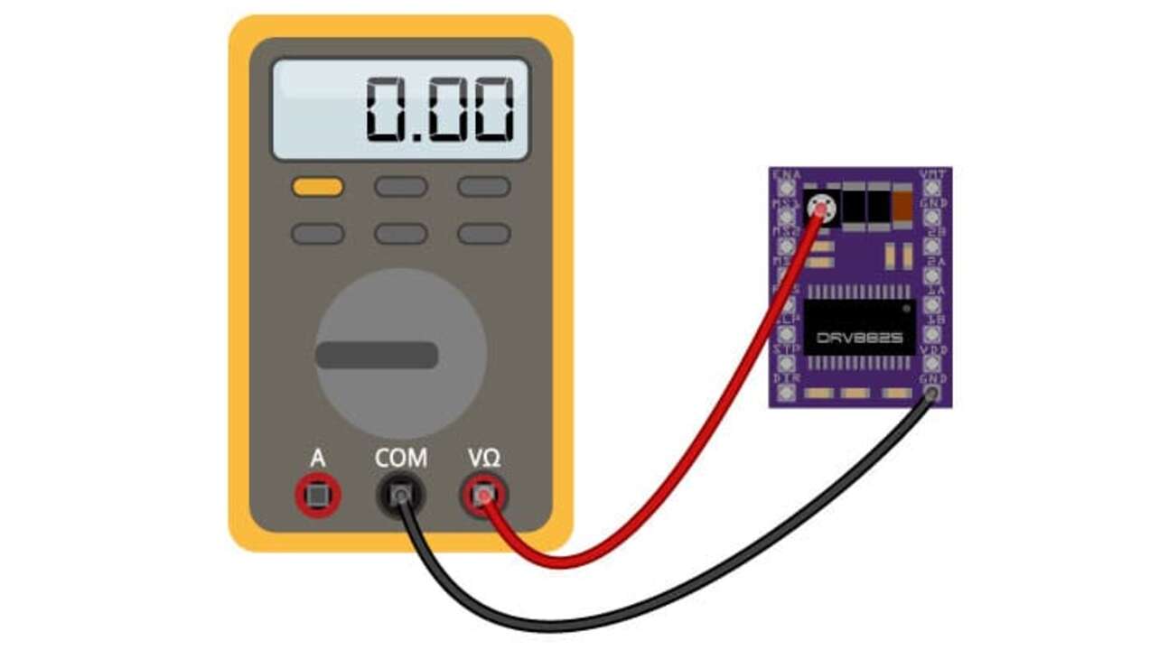
Then, first I prepared a breadboard with the connections and before move the potentiometer, I measured the refence voltage and I found out that all the drivers were not adjusted and they were set for a stepper motor of 2.5 A which is almost the double of the ones that I am using. Therefore, I proceed to set the current limit to 1.3 A which means that the refence voltage must be of 0.65 V because the formula to set the current limit is equal to the refence voltage over 2. After I adjusted al the motor drivers, I did a test on the air and it finally worked as expected. I was so happy because I late around two to three weeks to repair because it is hard to get the electrical components during pandemy.
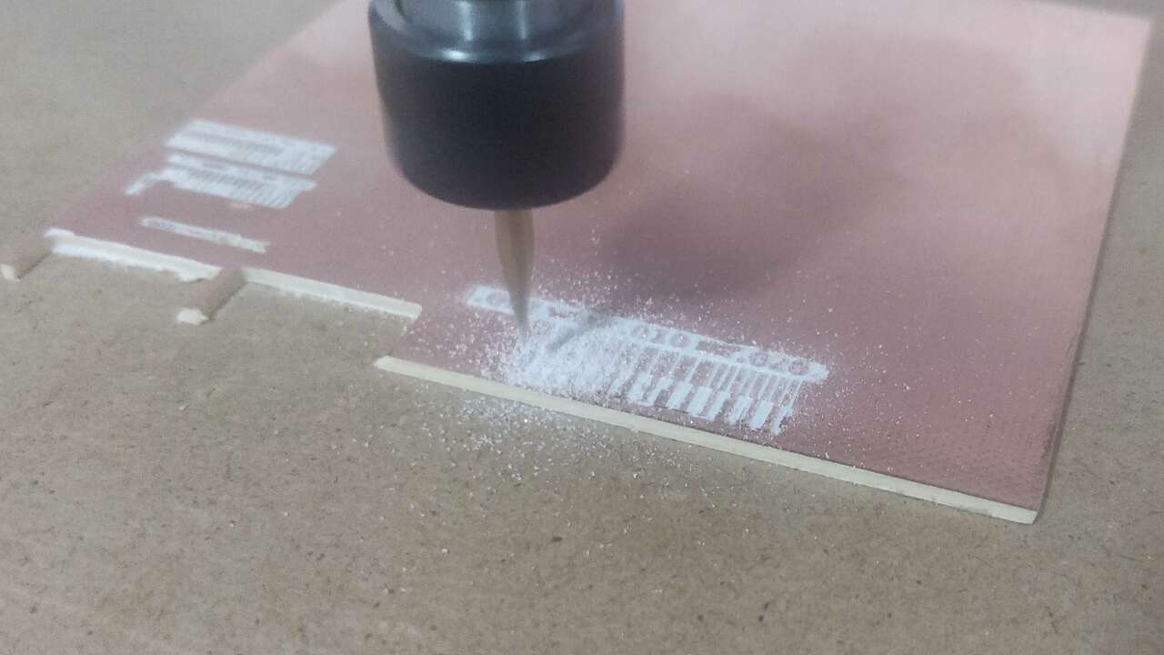
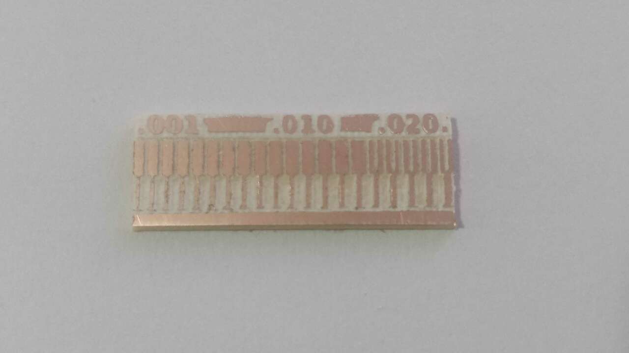
After the test on the air was perfom, I did all the required steps to send the good file to the machine and took some pictures during the process.
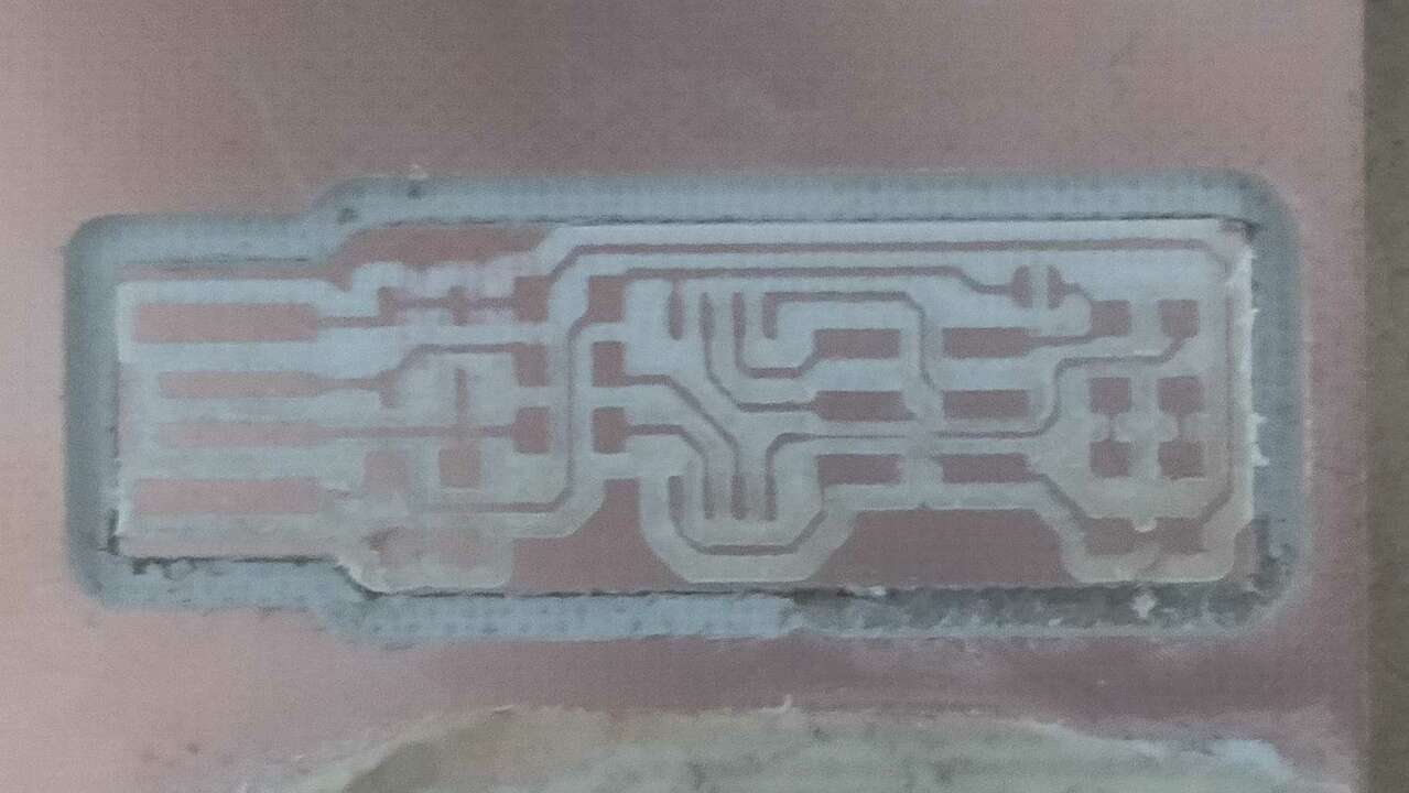
Later on, I perfomed the outline with the difference that in the initial setting I chose PCB outline instead of PCB traces. For the feed rate, I set the cut speed at 4 mm/s while the plunge speed at 2 mm/s. For the tool I chose a cut depth of 0.2, a stock tickness of 1.6 mm and a tool diameter of 2 mm. When the outline was done, I got this beatiful PCB.
I recorded a video durign the engraving process of the testing PCB where I was amazed by the precision of the machine. I was not expecting to have so high precision and resolution to create smalls PCB's. However, it proved otherwise and here is a video that shows it.
FabTiny ISP
Now that the machine is finally working as expected. I decided to do the Brian's FabTinyISP which is an AVR ISP programmer that I can use later during the FabAcademy. When you open Brian's website you can save the png files which look something like this:

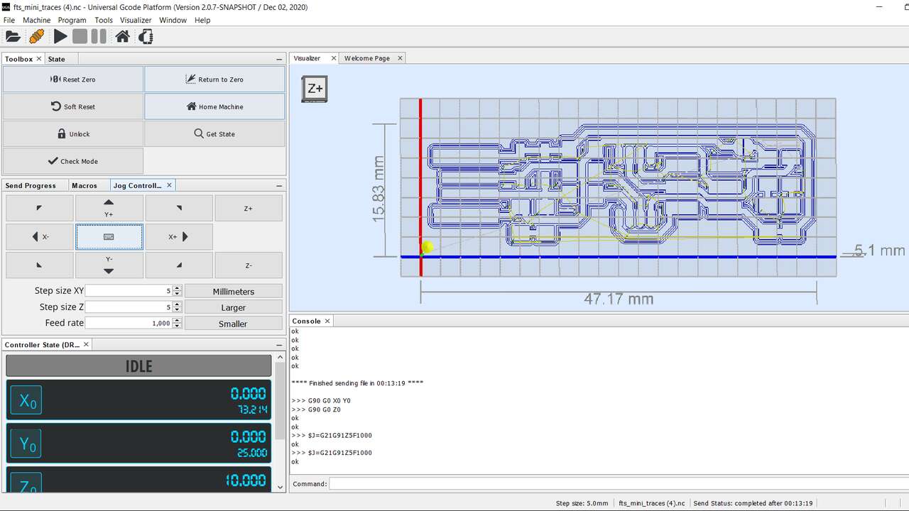
First, I created the gcode for the traces and the outline of the board with fabmodules. I set the same parameters that I used for the testing board.
When the gcodes were created, I proceed to upload the new file to the software and also zeroing the machine as was shown in the previous section. The picture above shows how the software looked like when I uploaded the engraving gcode.
The video above shows part of the engraving process that the machine executed to obtain the required PCB.
Later I send the outline cut and the machine is still working as expected. However, I set the cut depth to 1.6 mm and we can see part of the material at the bottom of the board. That excess of material can be removed by a cutter or something sharp that can cut the material.
Assembling the FabTiny ISP
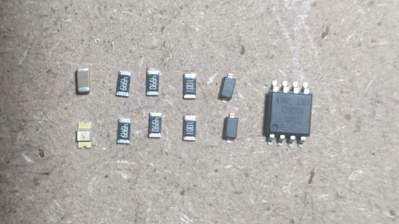
Once the board was machined, I went to Brian's website again to verify that I have all the electrical components to solder and obtain my programmer. The following table depicts all the required components along with its specifications:
The following table shows the bill of material to create this PCB.
| Quantity | Component | Model |
|---|---|---|
| 1 | Microcontroller | ATtiny45 |
| 1 | Ceramic Capacitor | 100nF |
| 2 | Resistor | 1k Ohm |
| 2 | Resistor | 499 Ohms |
| 2 | Resistor | 49 Ohms |
| 1 | Zener Diode | 3.3V |
| 1 | LED | Green |
| 1 | LED | Red |
| 1 | Pin header | 2x3 for SMD |
After verifing that I have all the components and the tools to solder, I sort my components in such a way that will be easy to identify where goes each item. I also used a 3d printed gripper that I created for 3d printing week to hold my pcb while soldering. The following two pictures shows the components and the board in the gripper.
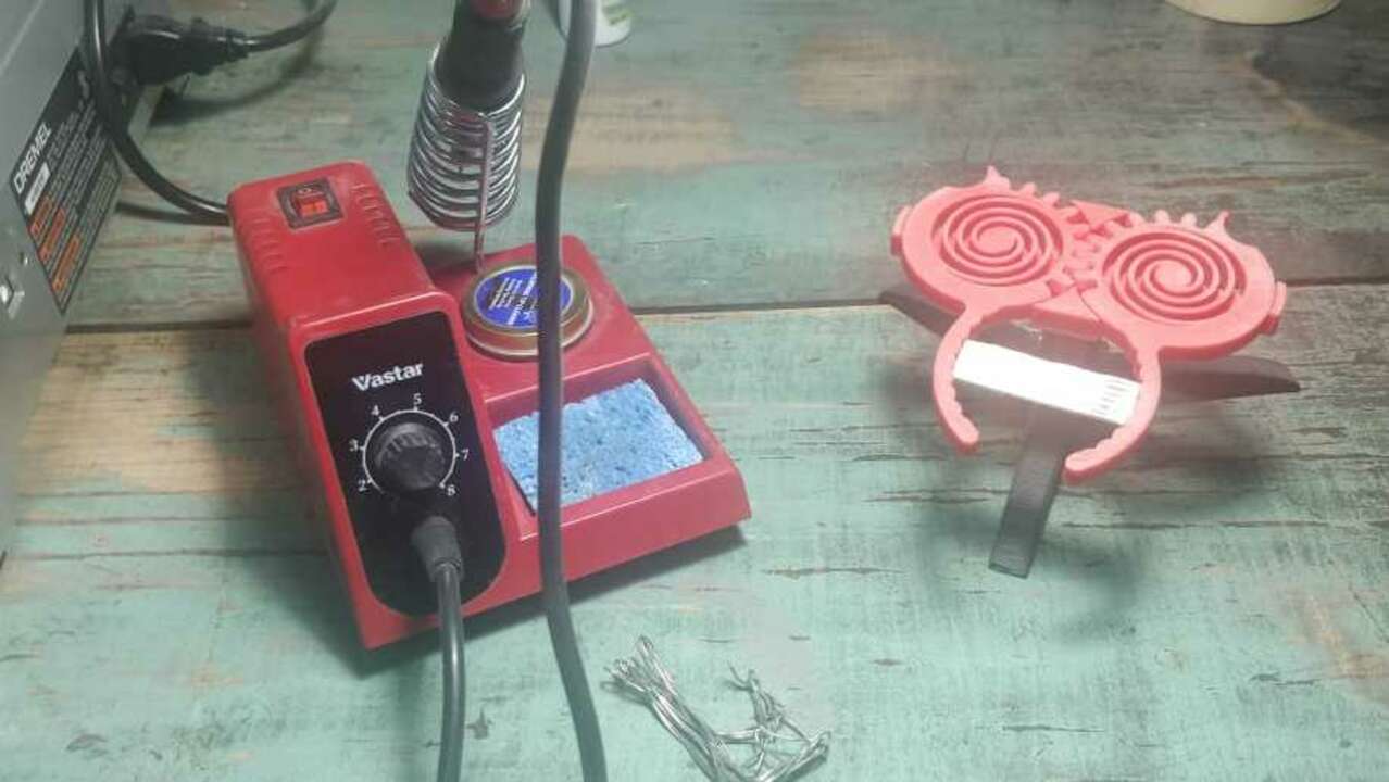
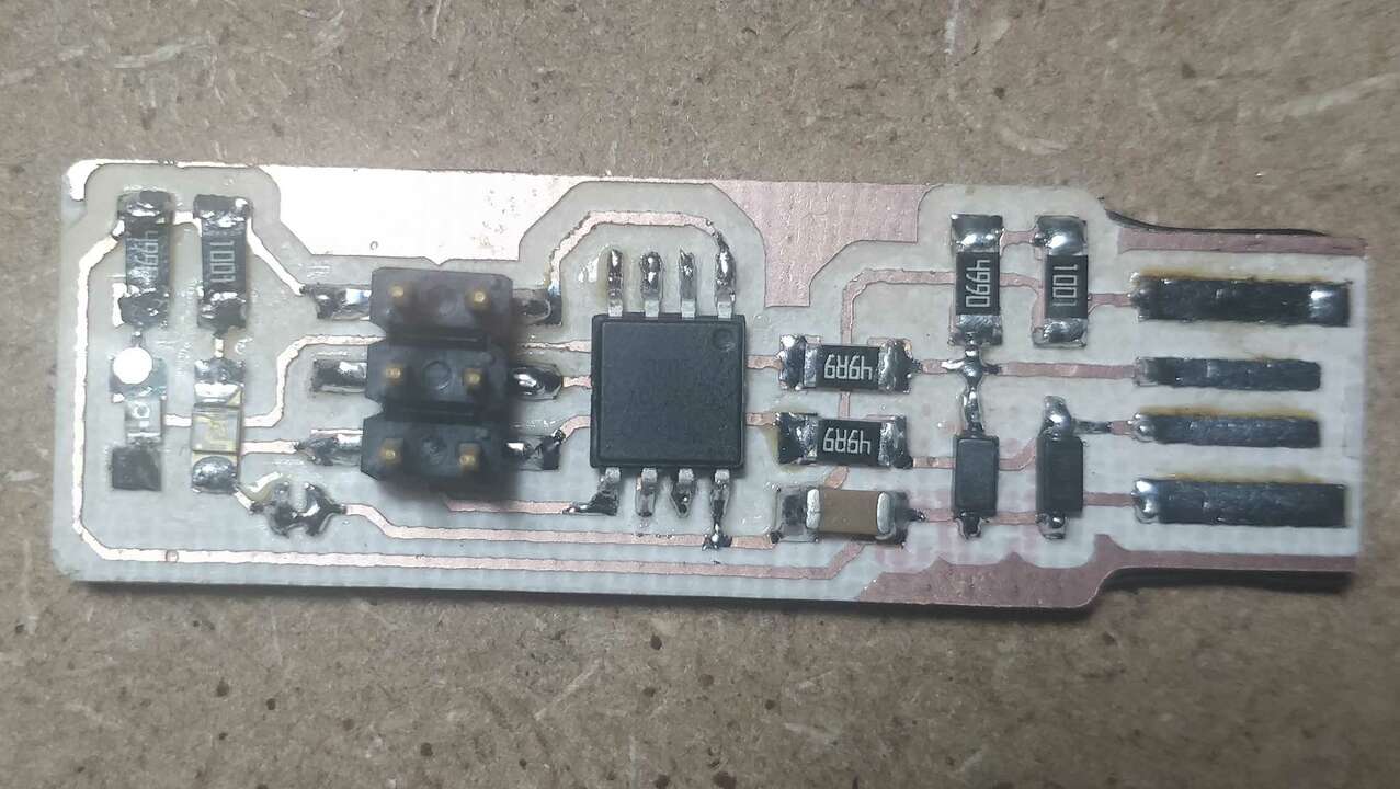
I already knew how to solder so I did not have troubles soldering the components into the board. However, the last time I solder was almost two years ago and at the beginning I had to remember the best techniques to do it. I think it looks good and it will work as planned.
Programming the FabTiny ISP
Now, it is time to verify that the board is working as expected and that it can be programmed as a programmer. The board looks pretty good but it is better to wait and see if the board is working. The first step was to connect an AVR programmer to my board with the ISP connector and later the programmer must be insert into an USB port of the computer just like the following picture shows:
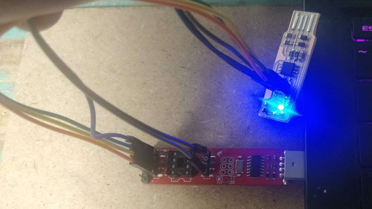
I also used Ubuntu to program my board because accoriding to Brian's website it is easier and better to do it in this OS. In case you are using the same operative system you can follow the steps above to program your programmer.
- Install avrdude with the following command
sudo apt install avrdude gcc-avr avr-libc make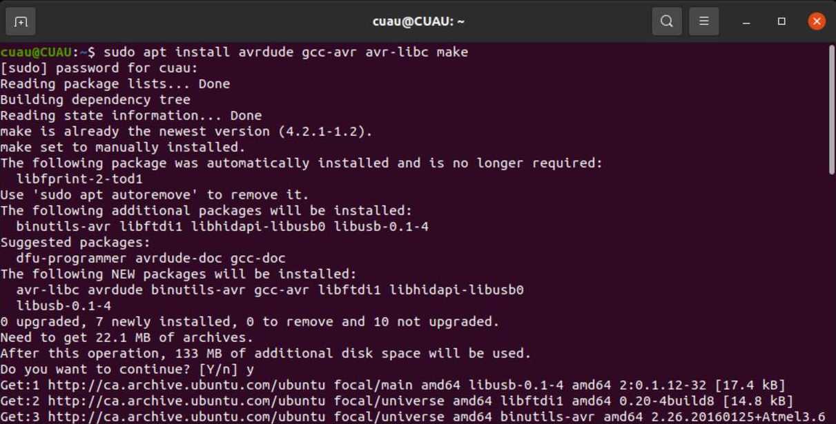
- Download the Firmware from here
- Unzip the firmware and place in a specific folder
- Move in the terminal to the folder where you saved the firmware
- Create the .hex file using the following command in the terminal
make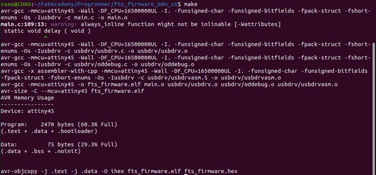
- Before keep preparing the files to be programmed, we can verify that ATtiny45 is being read by the programmer and it can accept files. In order to do this, we need to install a new package with the following command
sudo apt-get install libusb-dev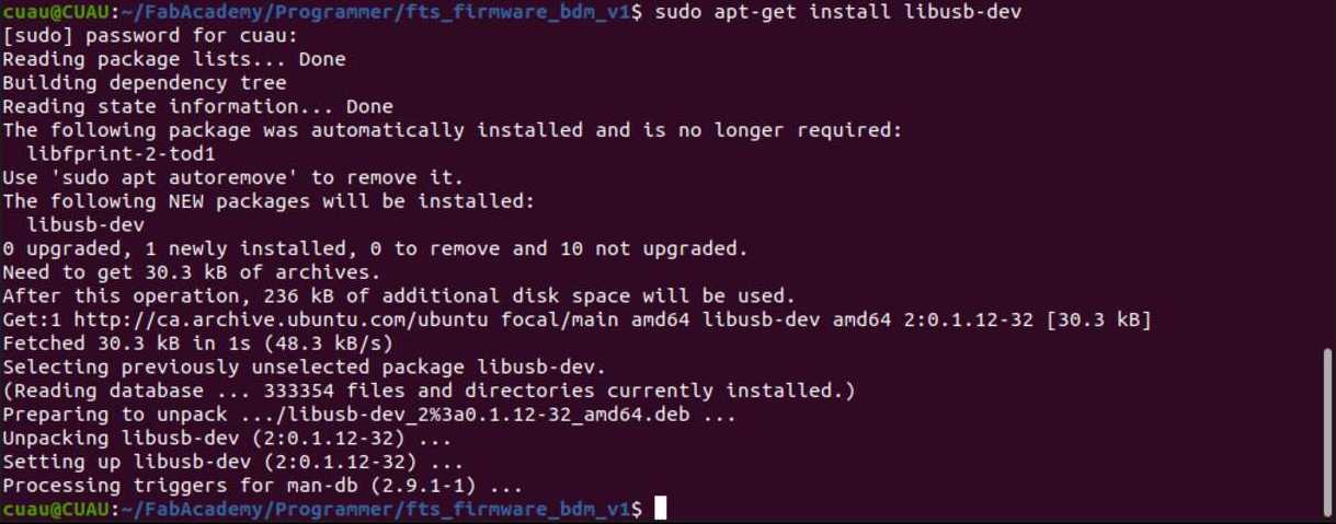
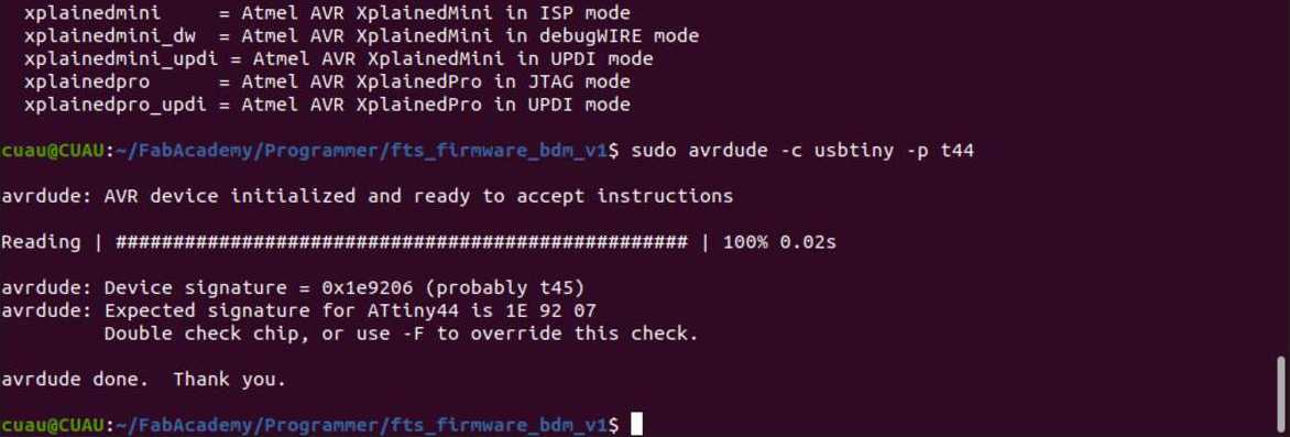
- Now we can do the verification process where AVRdude will tell us if the AVR device is ready to be programmed and also the device signature. If everthing is good, you must see a similar message that says that everything is good to go.
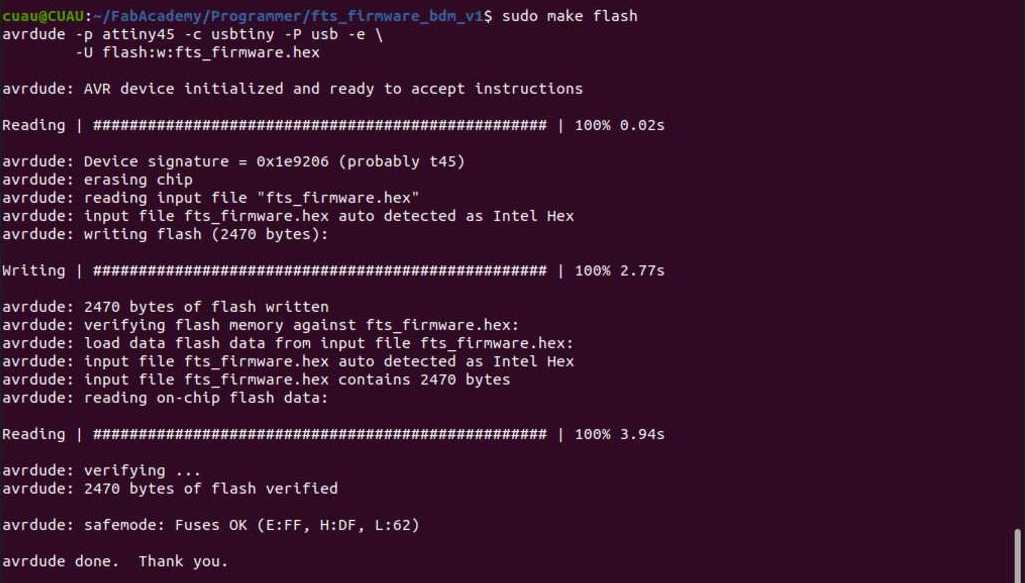
- It is time to erase the AVR and program its flash memory with the contents of the .hex file created previously. To flash this, you must write the following command:
- Once the flash memory has been succesfully programmed, we can proceed to set the configuration of the fuses. The fuses will disable the reset pin and will turn it into a regular GPIO pin to let the AVR use the reset pin to program other board, but not to be programmed. After this process is done, there is no comming back and you must verify that the previous steps were done correctly. Thus, we need to run the following command:
- The last step with the avrdude is to blow the reset fuse to ensure that the reset will never work again as a reset pin and insted as a GPIO. Then, write the following command and execute it.
make flash
If everything went as planned, you must see the following window. In case there was a problem you can go to Brian's FabTinyISP
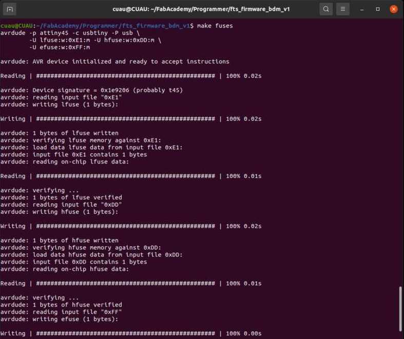
make fuses
Do not be afraid if you see multiple prograss bars that are showing the process of the fuses.
Before keep going with the process, you must verify that the device is been seen by the computer. In my case I use Windows 10 to verify it and the only thing I did is to write device manger in the search of windows and a new window will show up where you must go to COM devices and if you see a new device when the usb is connected it means the usb funciton is good.
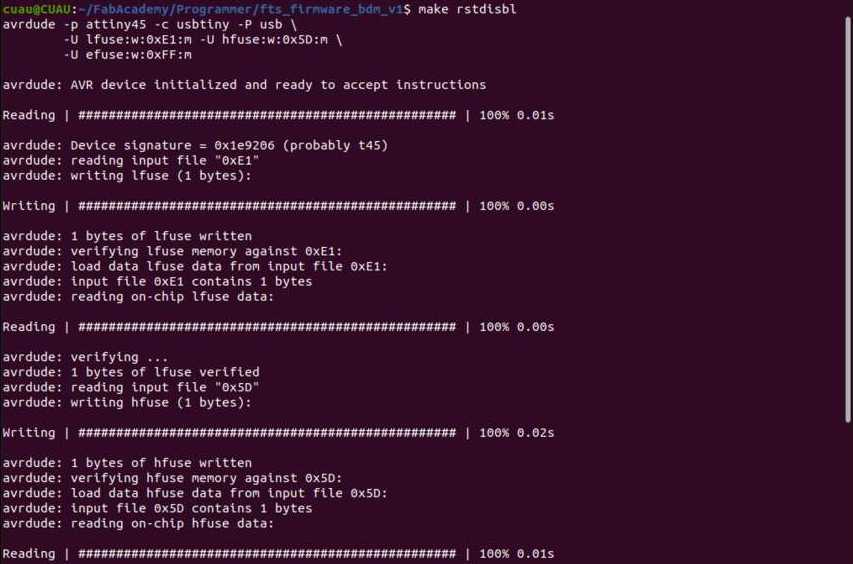
make rstdisab
This command does the same as the make fuses with the difference that the actual command includes the reset disable bit during the process.
Finally is time to test the programmer and enjoy it. In my case, I followed the previous steps and I recorded a video that shows how my programmer is detected by the computer
Files created
Useful Resources