
Week 14 - Networking & Communications
assignment
individual assignment:
      design, build, and connect wired or wireless node(s)
      with network or bus addresses
group assignment:
      send a message between two projects
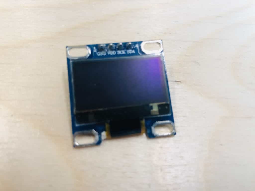
I2C oled screen
I've decided to start by connecting my custom ESP32 board to an I2C oled screen, size 0.96". These screens are known for being cheap and easy to use. I bought from Amazon and they were £4 each.
Quick tutorial
I've used one before but it was some time ago, so I chose to refresh my mind with a quick tutorial:
 https://randomnerdtutorials.com/esp32-ssd1306-oled-display-arduino-ide/
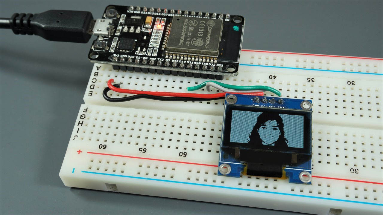
Missing pins on my custom board
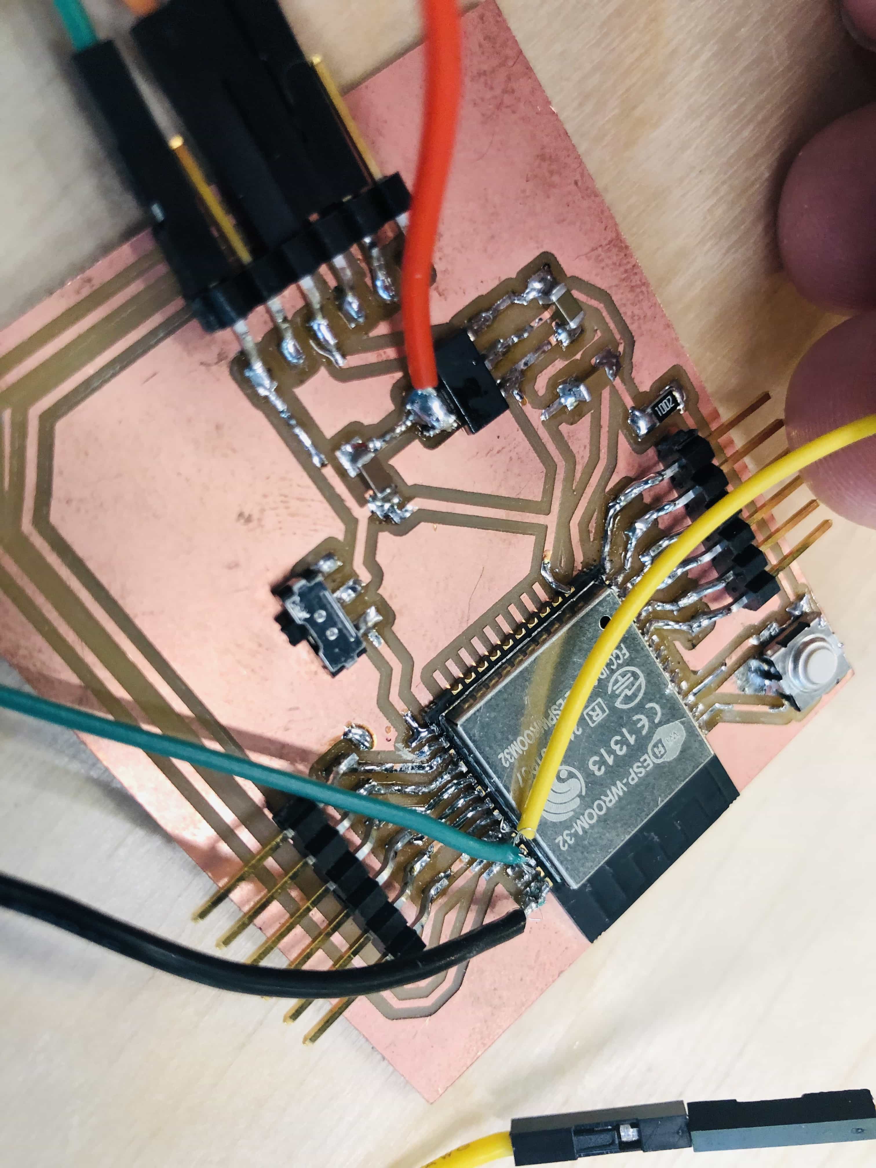
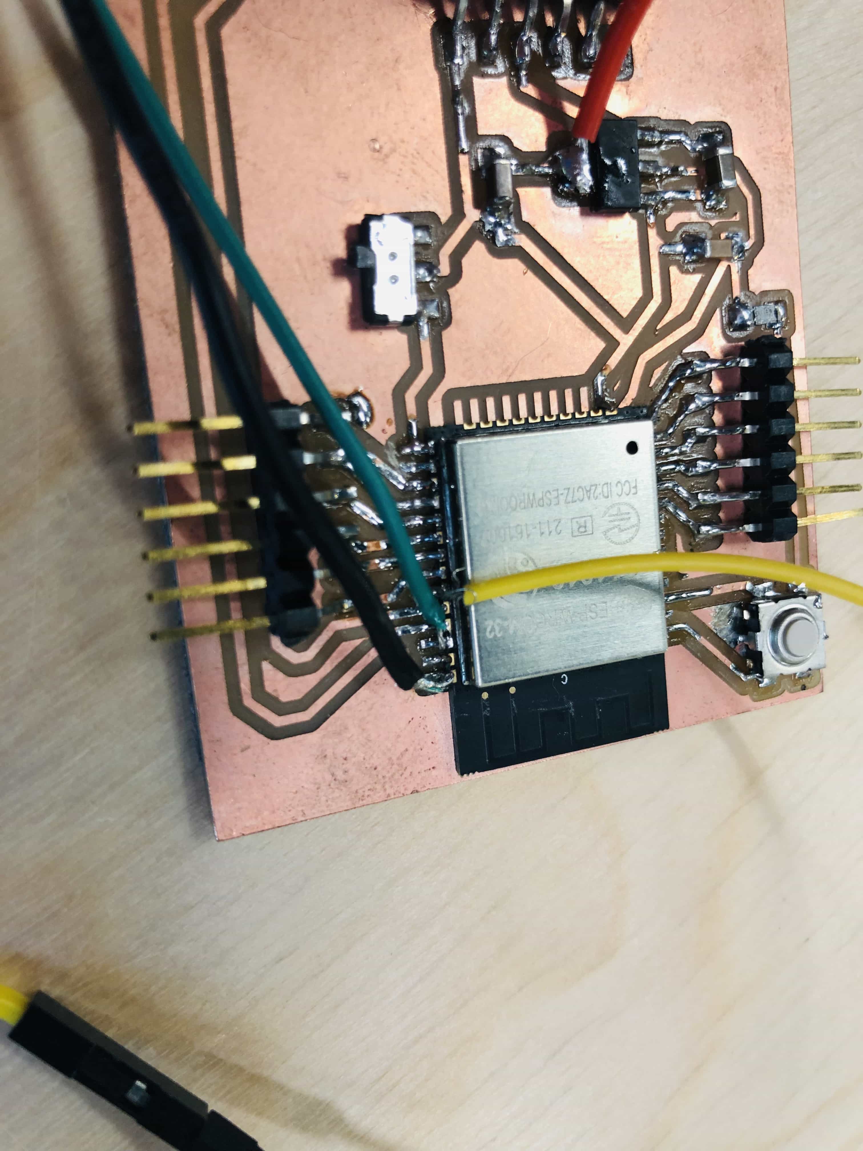
When I've tried to make this simple circuit, I've realised a silly mistake I've made. I put pin headers onto 12 of the GPIO pins on my ESP32 chip. This seemed like a generous amount that would support all possible needs of my project. I totally forgot to add the following:
- Ground pin
- VCC pin (3.3V or 5V would have been fine)
- Clock and data pins
To solve this problem, I decided to solder some jumper wires directly onto the actual chip. This was fiddly and I required my magnifying glasses, but it has solved the problem for now.
Circuit and code
The circuit is simple and just requires a connection of 5V, ground, clock and data pins. I've checked the datasheet for my ESP32 and see that data is GPIO21 and clock is GPIO22.
I wrote a simple script from scratch, borrowing parts from the tutorial above:
#include <U8x8lib.h>
#ifdef U8X8_HAVE_HW_SPI
#include <SPI.h>
#endif

U8X8_SH1106_128X64_NONAME_HW_I2C u8x8(/* reset=*/ U8X8_PIN_NONE);

void setup() {
  // put your setup code here, to run once:
  u8x8.begin();
  u8x8.setFlipMode(1);
  u8x8.setFont(u8x8_font_chroma48medium8_r);
}

void loop() {
  // put your main code here, to run repeatedly:
  u8x8.setCursor(0, 0);
  u8x8.print("Fab Academy 2021");
  delay(1000);
  u8x8.clearDisplay();
  delay(1000);
}
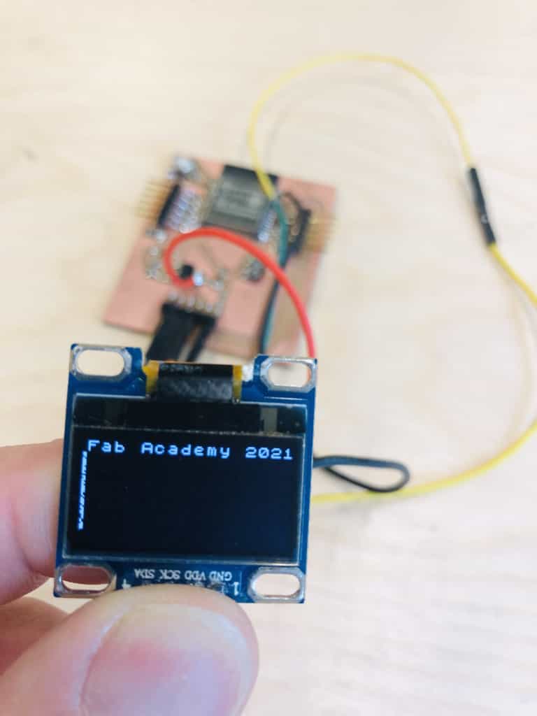
My code should flash the text 'Fab Academy 2021' and I'm pleased to say it worked great:
Multiple displays
I decided to ahead and add a 2nd display. I tried and failed to do this in the past and so I was keen to get 2 separate displays working. Sadly I was unable to do this but I learnt a lot in the process. I found tutorials where people were showing how to use multiple displays but in each case they were doing one of the following:
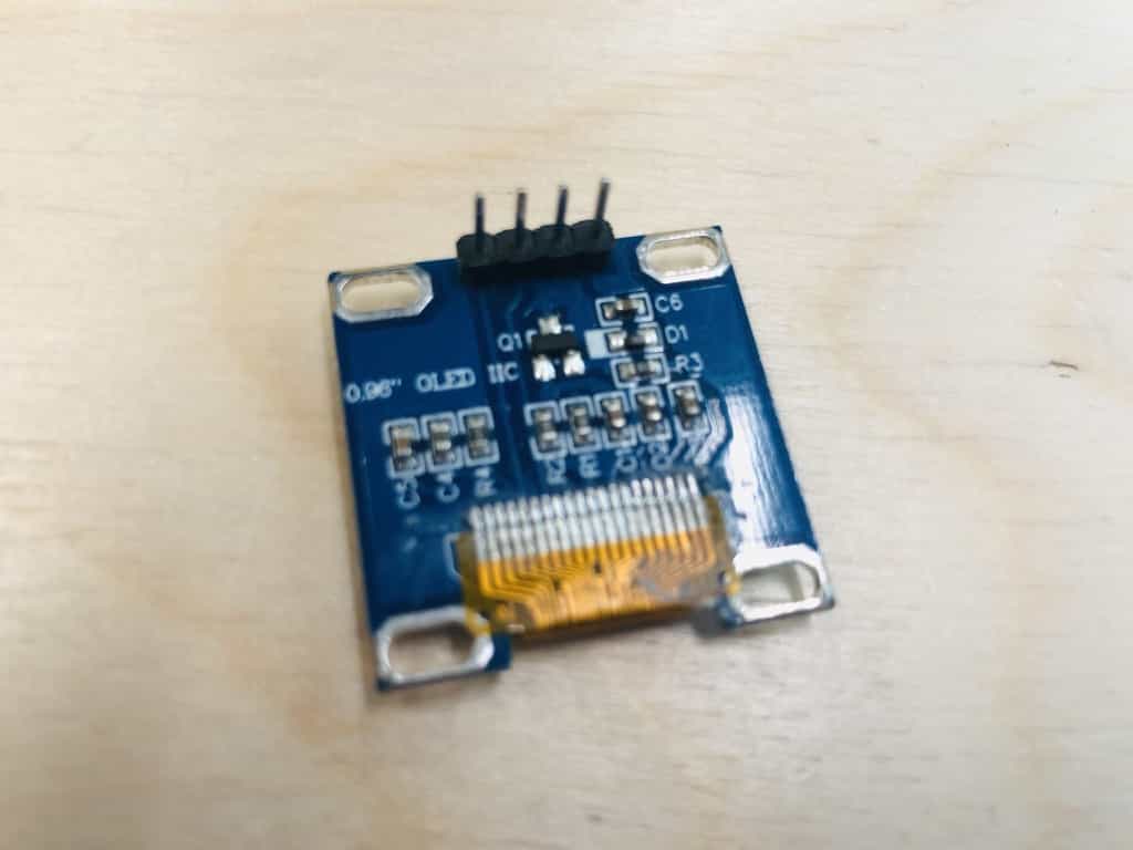
- Using oled displays which had a configurable I2C address. The back of the display had one or more resistors that could be de-soldered and then re-soldered into a number of positions. Many oled screens had just 2 positions and I noticed these were sold cheaply on Amazon. There were also some screens with up to 8 resistors which would give you up to 127 different I2C addresses. Sadly my oled screen was the type where the I2C address was hard-wired in and could not be changed.
- Using an extra component called a Multiplex TC9548. This board connects to your microprocessor and you can then connect multiple I2C devices to the TC9548. This allows you to use multiple I2C devices independently, even if they all have the same unique I2C address hard-wired in.
- Using a selection of I2C devices that all had different addresses wired-in.
- Using a different protocol such as SPI for the communication with the displays.
- Using multiple displays with the same I2C address, but showing the same information on each display.
- Using multiple displays with the same I2C address, but combining together to effectively make a single larger display.
I have the wrong screens
It turns out I bought a pack of 5 oled screens that all have the same I2C address and one which cannot be changed. Given my goal of having 2 separate displays that show separate data, I'm unable to achieve this without buying either a new display or the TC9548 component. Its a little frustrating but I feel like I've learnt a lot through the process of trying to do something that was not technically possible.
I've decided not to spend money on more displays because I have 3 available which work just fine for now. If I have a project in the future that requires more than 1 display, I shall make sure to buy new displays with a configurable address.
Link to ESP32 board design
All the design files for my custom ESP32 board are available for download in my Week 6 assignment:
Files for download
Link to the group assignment:
Back to homepage: