Week 13 - Output Devices
assignment
individual assignment:
add an output device to a microcontroller board you've designed,
and program it to do something
group assignment:
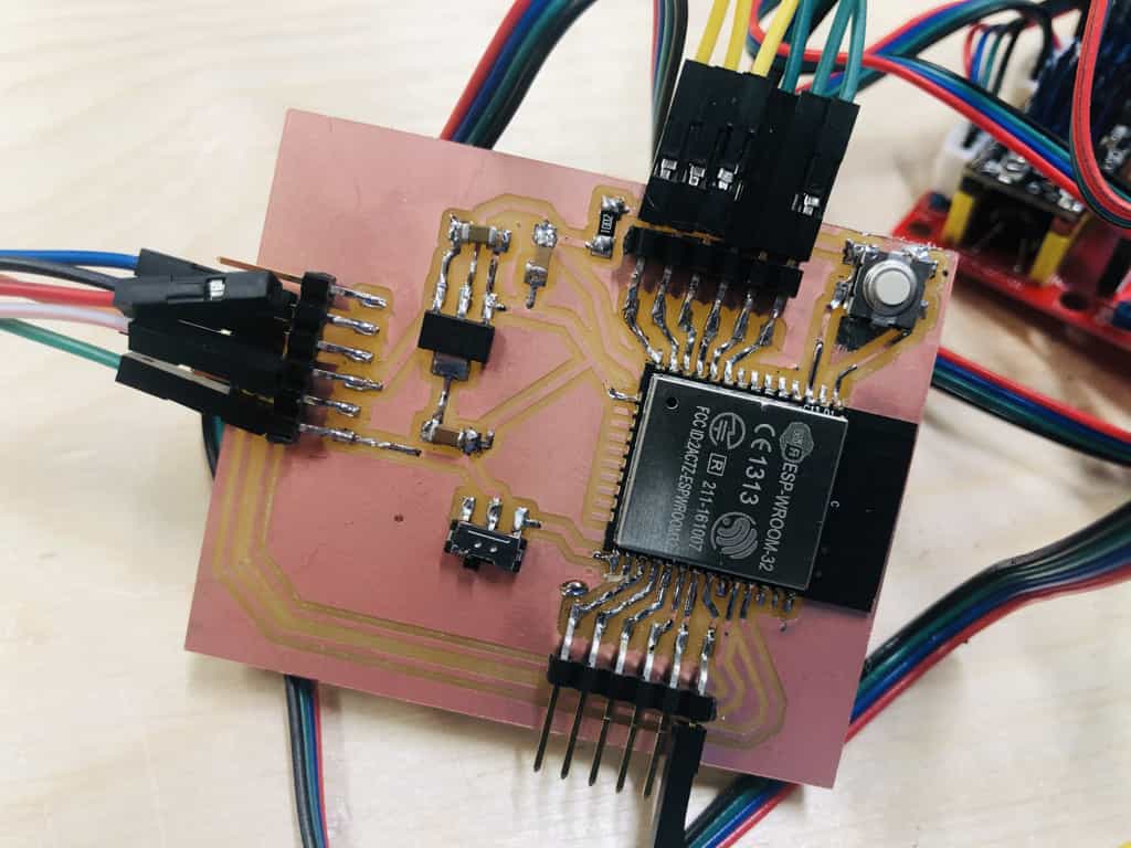
measure the power consumption of an output deviceESP32 custom board
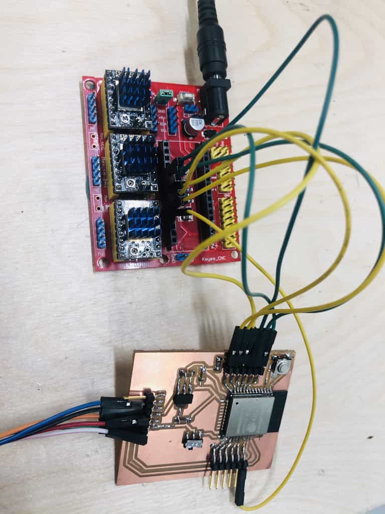
I'll be using my custom board that uses the ESP32 chip. I like this board because I'm familiar with ESP32 and it allows me to use WiFi and Bluetooth should my project later require it.
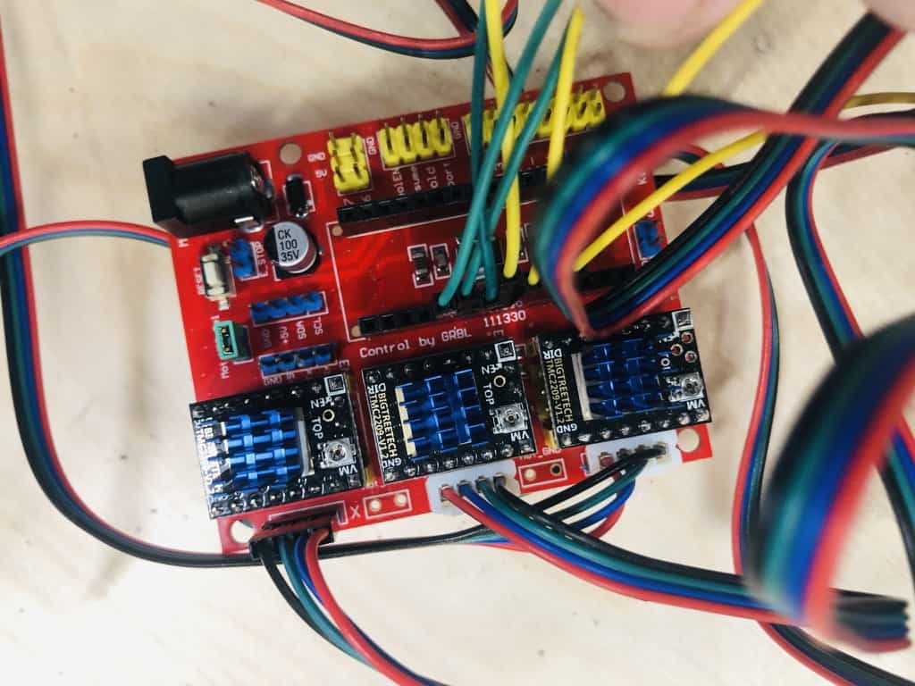
CNC shield
I'll also be using a CNC shield. This is designed for an Arduino Nano but it is easy to connect to my custom board using jumper wires. This board saves a lot of messy wires and components. Each stepper motor requires a driver and each driver requires a capacitor, 5V logic, 12V power for the motors and some other resistors and connections. Its so much easier to just use this board but if I proceed with this final project, I will most likely made my own custom version using our Roland milling machine.
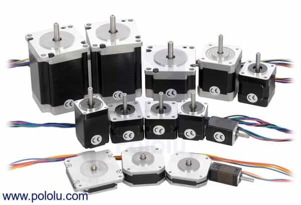
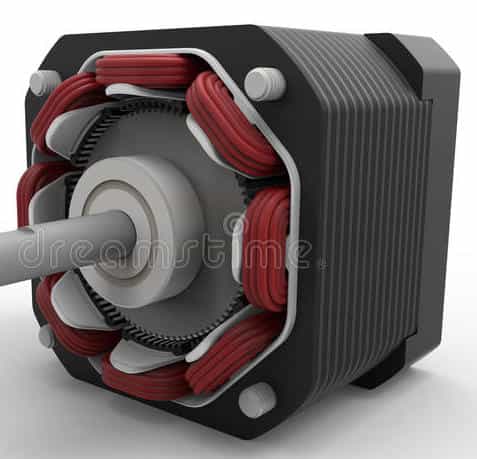
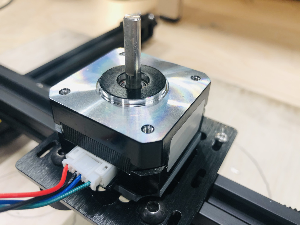
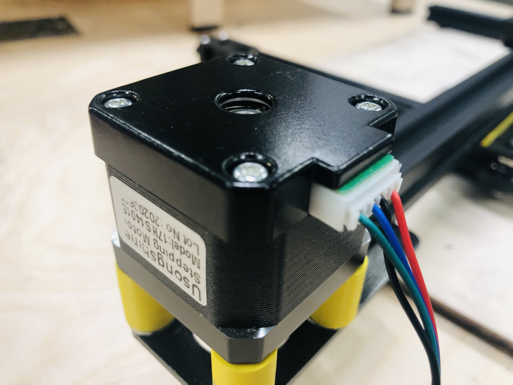
Stepper motors
This week I will be almost completely focussed on stepper motors. I already have 3 stepper motors on my project and technically, they all work. The problem is that they're noisy and jumpy.
My goal for this week is to get all 3 stepper motors on my project, working in harmony and with minimal noise. My motors are all NEMA 17, two of them with 1.7A rated current and another smaller version with 1A rated current.
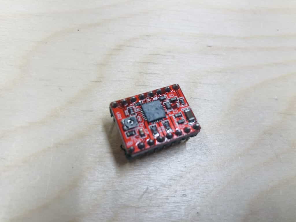
Stepper motor drivers
The first drivers I've used are the A4988. Here they are loaded up on my CNC shield:

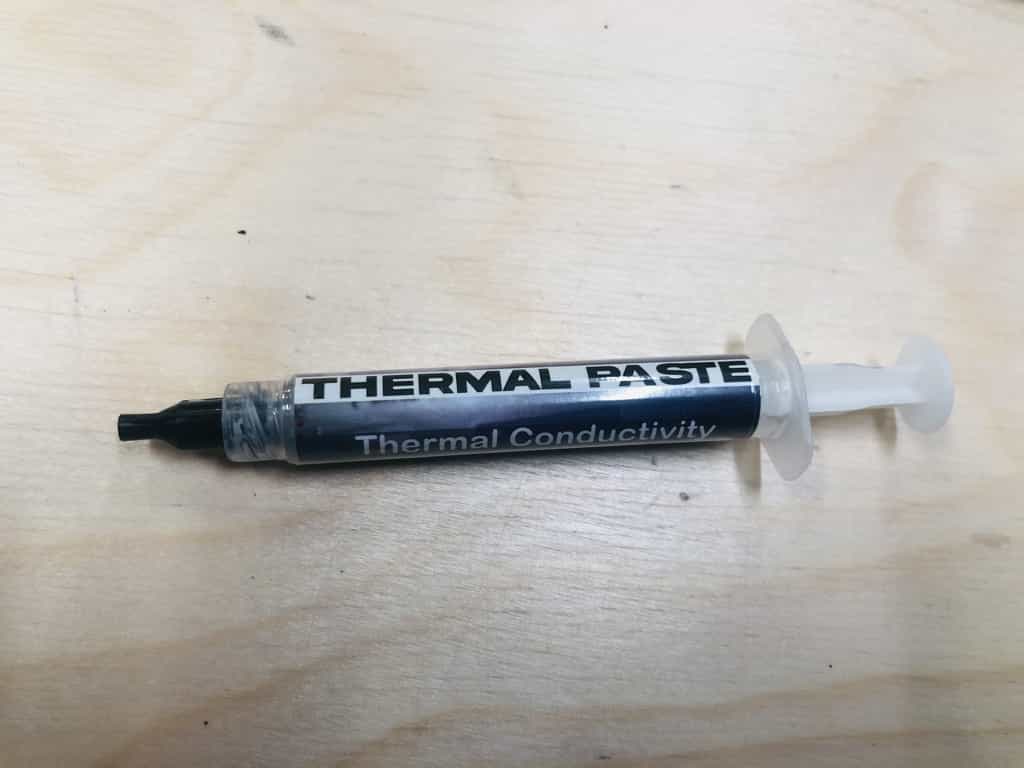
Thermal paste
I've had issues with these drivers over-heating. So far I've blown 6 of them and so after a little research, I found some advice to use thermal paste. I bought a one part version on Amazon but a lot of people were recommending a 2 part version which was not easily available in the UK.
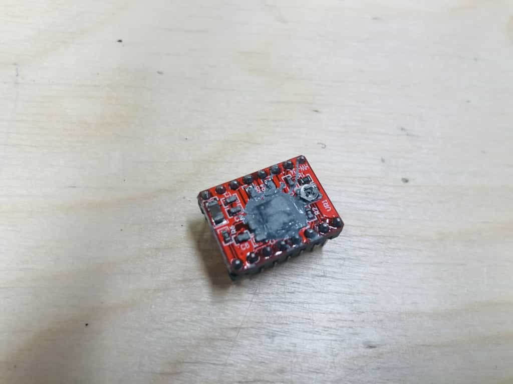
Don't do this
Its way too much. I thought it would stay in position on the chip but it is less viscous than I thought.
Do this:
You don't need too much.
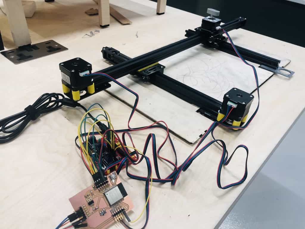
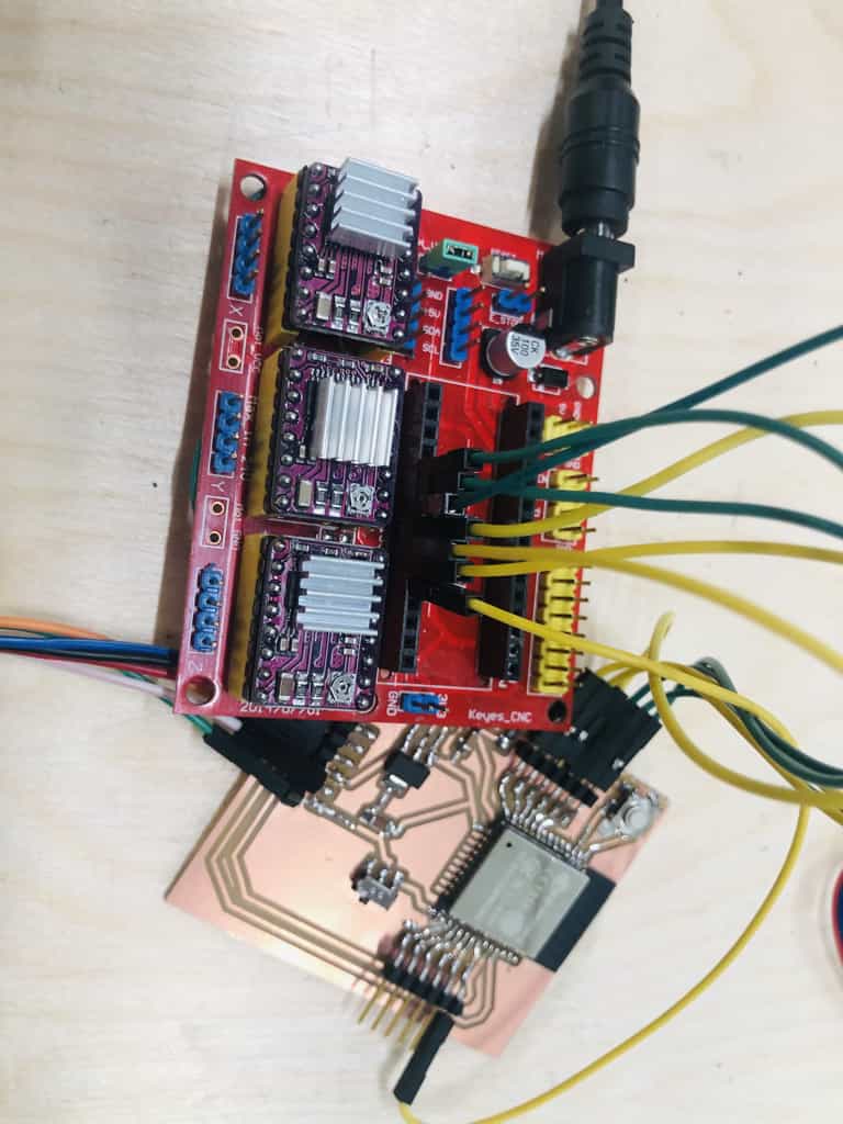
ESP32 board with CNC shield and A4988 drivers
I'm ready to go with this configuration. I've used thermal paste which I'm hoping will help prevent the over-heating I experienced previously:
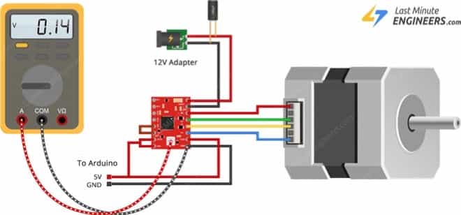
Setting the current for each motor
Each A4988 driver has a potentiometer which allows you to limit the current passed to the motor. The formula to calculate
There is a simple formula that allows you to calculate the Vref value:
My larger motors are rated at 1.7A and my smaller motor is 1A. I shall substitute these values into the equation above:
Larger motor(1.7A) - (The vref value should be 0.68 volts)
Smaler motor(1A) - (The vref value should be 0.4 volts)
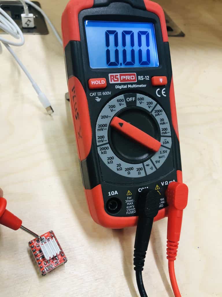
This isn't a great photo because I'm working alone and can't photo the actual process. You need to check the voltage by pressing the red lead to the potentiometer and the black lead to the ground pin on the chip. You turn clockwise to reduce the voltage and anti-clockwise to increase it. You need to keep adjusting and checking the voltage until you get the values above.
The easiest way for this process above is to attach a crocodile clip from the multimeter onto a screwdriver. Then you can read the voltage while you make the micro adjustments.
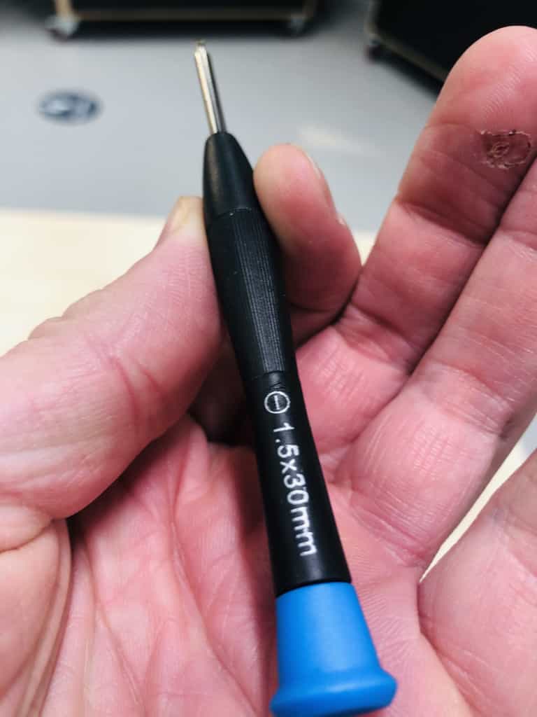
Correct screwdriver
I considered this important enough to give it a title! I tried more than 10 different screwdrivers on the small potentiometer and none of them would make a good connection. As a result of using a poorly connecting screwdriver, I repeatedly damaged the potentiometer. If you keep screwing it with the wrong screwdriver, it eventually falls off and the driver is useless.
I bought a new set of micro screwdrivers and surprisingly, the only screwdriver that would work was a flat head screwdriver of 2mm. Its a bit of a red herring because the screw has a crosshead but I could not make it turn with anything other than a flat head 1.5mm.
Here it is, the only screwdriver in the world that can adjust the potentiometer on these drivers:
Noise levels with stepper motors
I'm going to demonstrate the noise level with a few different setups, to show the impact of changing motor speed, step count and choice of driver.
Lets start with the A4988 drivers in full step mode and using a speed that has 1000 microsecond delay between Step inputs.
This video shows a simple sequence where the motor does the following:
- Moves both ways along the X axis
- Moves both ways along the Y axis
- Moves simultaneously along X and Y axis in both directions.
Test 1 - A4988 drivers, full-step mode and speed delay of 1000 microseconds
Test 2 - A4988 drivers, full-step mode and speed delay of 500 microseconds
I couldn't understand why there would be so much noise when combining the 2 motors together. Then I realised my mistake. I had created a 'for' loop where it would run both motors using the same delay of 1000 microseconds. This means there is an actual delay of 2000 microseconds because the other motor needs to operate in between the step signals.
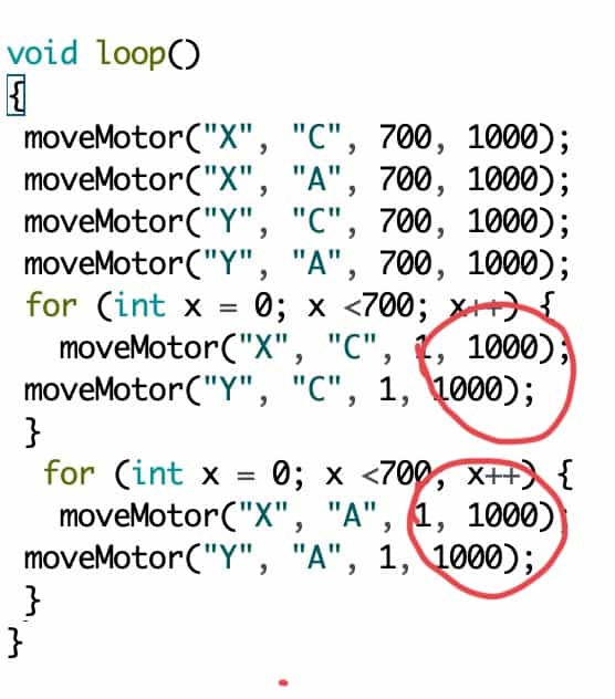
I've now changed the delay to be 500 microseconds which means the motion will be the same effective speed as when they were moving across just one axis. Here is the result and you can hear there is a lot less noise:
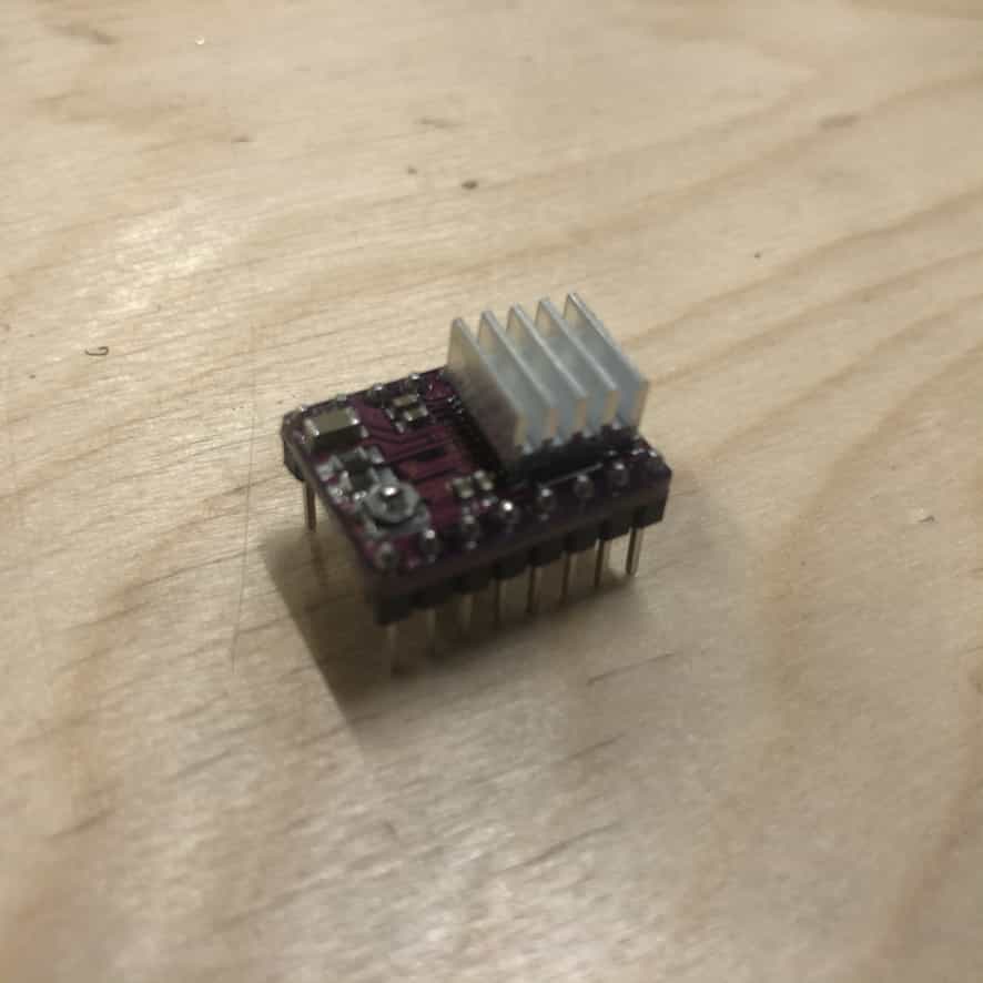
Test 3 - DRV8825 drivers, 1/32 step mode and speed delay of 500 microseconds
A lot of people online have recommended DRV8825 drivers in place of A4988 and given the issues I'd had with broken potentiometers and burnt out chips, I thought I'd give it a go. Here is the new chip and here is my CNC shield loaded up with 3 of them.
I've gone through the same process to set the current limit correctly. A quick trial shows that these work just fine but the noise levels are exactly the same as the A4988. So now I will try increasing the step count from 1 full step to 1/32 steps.
Sadly I didn't record this and I've now blown my ESP32 board and can't make a new video in time for our lecture. But I can tell you the noise was reduced a noticeable amount. There was still noise, but a nice improvement.
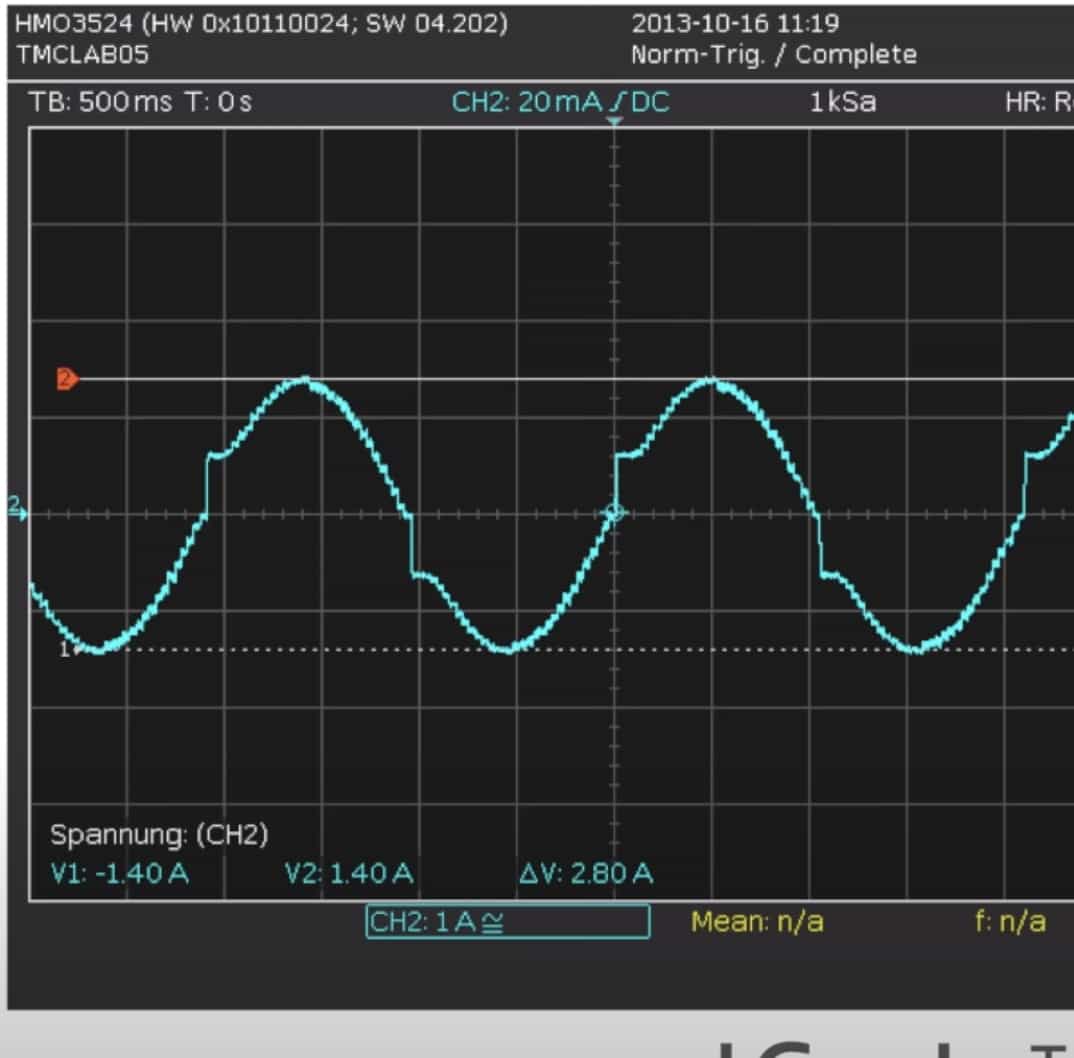
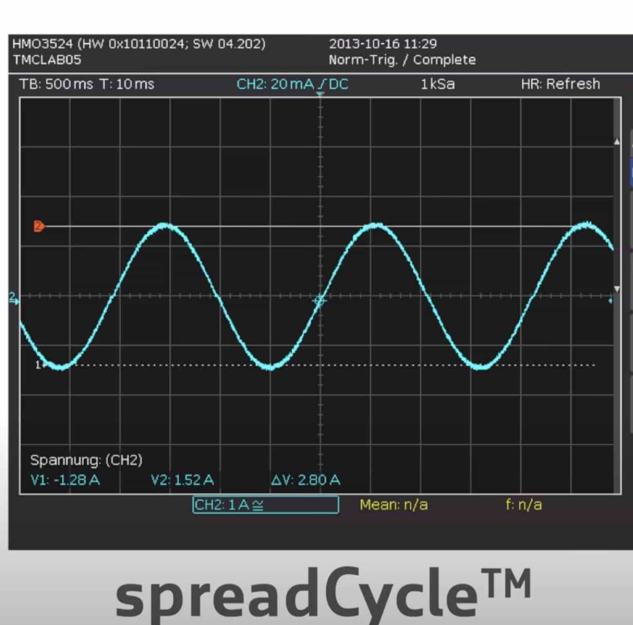
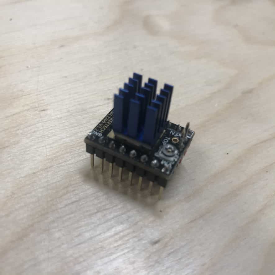
Test 4 - STM2209 stealth chop drivers, 1/8 step mode and speed delay of 500 microseconds
My tutor Andrew recommended these STM drivers made by German company Trinamic. This screenshot from their youtube video shows how their drivers smooth out the current between steps:
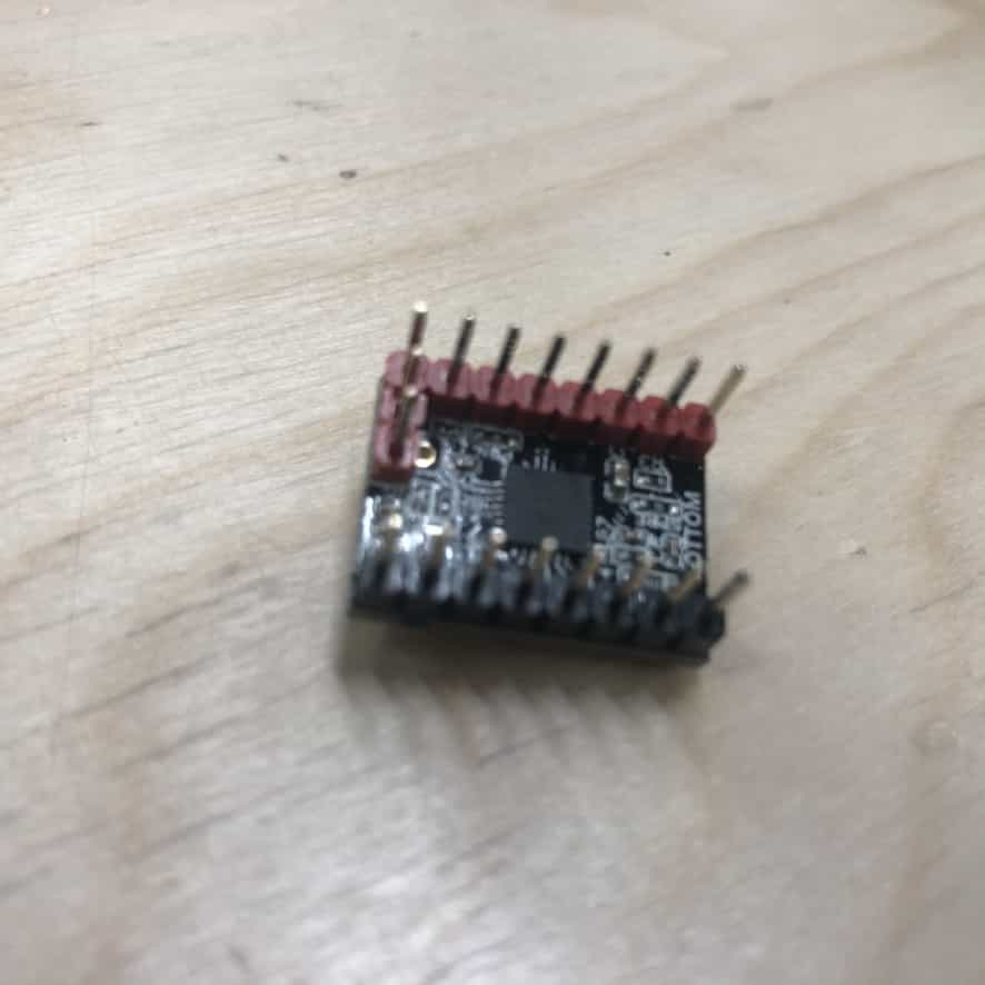
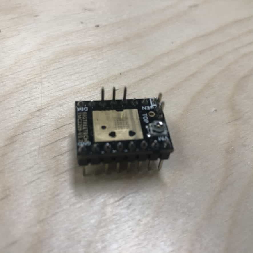
This is how the drivers arrived. I've not seen this design before. The chip is underneath and there is a pad on the top where you can place the heatsink.
I fitted the heatsink supplied and I chose not to use thermal paste because I was excited and couldn't be bothered to delay the stealth chop.
I've loaded all 3 drivers onto my board and set the current limit in the same way.
These drivers did not work at first and it took me some time to find the solution. Although they advertise how easy it is to do a straight swap with A4988/DRV8825 drivers, this is a little misleading. There is an enable pin that must be pulled low (the other drivers it needed to be high) and so I needed to add an extra jumper wire so I could set the enable pin LOW.
Now finally I had everything working and here is the result. Sadly I can't recreate the exact experiment above because I have blown my board and don't have time to re-make one in time for the lecture. But the video illustrates the point well. These drivers are magical and they really do make the motors silent. The noise you hear is simply the gantry moving along the aluminum rail.
Code
I've chosen not to use any libraries. Neil recommends this approach for projects like mine where you're doing something a little unique. Its helpful to have complete control and flexibility over what you're doing. I've created a set of functions which act like my own custom library.
moveMotor() function
This function tells the motor to move. It takes 4 parameters which allows you to specify:
- Which motor to move
- Which direction to move it
- How many steps to move it
- What speed to move it
void moveMotor(char axis, char direction, int numberOfSteps, int motorSpeed) {

  if (axis == 'X') {
    stepPin = XstepPin;
    dirPin = XdirPin;
  } else if (axis == 'Y') {
    stepPin = YstepPin;
    dirPin = YdirPin;
  } else if (axis == 'Z') {
    stepPin = ZstepPin;
    dirPin = ZdirPin;
  }

  if (directiony == 'C') {
    digitalWrite(dirPin, LOW);
  } else {
    digitalWrite(dirPin, HIGH);
  }

  for (int x = 0; x < numberOfSteps; x++) {
    digitalWrite(stepPin, HIGH);
    delayMicroseconds(motorSpeed);
    digitalWrite(stepPin, LOW);
    delayMicroseconds(motorSpeed);
  }
}
straight() function
This function can be used for moving the skateboard in a straight line across either the X or Y axis. It takes 5 parameters and allows you to:
- Choose which motor to move
- Choose which direction to move
- Choose how far to move
- Choose the start speed
- Choose the finish speed
void straight(char axis, char dir, int distance, int startSpeed, int finishSpeed) {

  int straightMotorSpeed = startSpeed;
  int counter = 0;
  for (int x = 0; x < distance; x++) {
    counter = counter + 1;
    moveMotor(axis, dir, 1, straightMotorSpeed);
    straightMotorSpeed = round(float(startSpeed) + (float(finishSpeed - startSpeed) * (float(counter) / float(distance))));
  }
}
turn() function
This function is used for moving the skateboard in a circular pattern. In addition to moving the X and Y axis, it also rotates the 3rd motor to make sure the skateboarder is turning as it travels along the perimeter of a circular pattern.
Acceleration challenge
Adding acceleration to this function was complex because the first thing I had to do was remove the natural acceleration that comes with a circular pattern. As you move around a circular pattern there are different proportions of movement on the X axis relation to the Y axis. I'll give 2 examples to illustrate the difference:
Example 1 - Equal proportions of X and Y movement
Sometimes when you move from one point on a circle to the next, the X and Y axis will both be required to move by 1 step. That means the distance you have travelled is actually 1.41 steps. Its easier to understand this if you picture the hypotenuse of a right-angled triangle with 2 sides of length 1 unit. If your desired motor speed requires a delay between steps of 100 microseconds, you would want to set the delay on each motor to average 70.5 microseconds. This means you will have a total delay of 141 microseconds, during which time you travel a distance of 1.41 steps. This means you achieve your desired speed of moving 1 step every 100 microseconds.
Example 1 - Unual proportions of X and Y movement
Some sections of the circle may require a single step of 1 motor and several of the other. Lets imagine that moving from 1 point on the circle to the next required to move the X axis by 1 step and the Y axis by 10 steps. In this example you're moving a total distance of 10.05 steps. This means your total delay should be 1005 microseconds which you want to separate into 11 equal delays. So in this example the delay between steps should average 91.36 microseconds. This is different to the 70.5 microsecond delay in the example above. My function is constantly re-adjusting the delay to remove this natural acceleration.
Now add your own acceleration
Now is the fun part where I get to add my own acceleration!! All of the work above is simply to stop the skateboard from moving around a circular pattern with inconsistent speed. Now I need to add my own acceleration because I may want the skateboarder to start slow and speed up, or vice versa.
Here is the complete code for my turn() function. It takes 7 parameters which allows you to:
- Choose the radius of the circle you wish to travel around
- Choose your X and Y distance from the circle centre
- Choose the direction you wish to travel around the circle
- Choose the percentage of the circle you wish to travel
- Choose the start speed
- Choose the finish speed
void turn(int radius, int XdistanceToCentre, int YdistanceToCentre, char dir, float percentage, int startSpeed, int finishSpeed) {

  int oldXmagnet = -XdistanceToCentre;
  int oldYmagnet = -YdistanceToCentre;
  int oldXcircle = -XdistanceToCentre;
  float oldYcircle = -float(YdistanceToCentre);
  int newXcircle;
  float newYcircle;
  char Xdirection;
  char Ydirection;
  int circleMotorSpeed;
  int Xcounter = 0;
  int Ycounter = 0;
  float Zcounter = 0.0;
  float Zfigure = radius / 400.0;
  int mycounter = 0;

  for (int x = 0; x < ((float)radius * 4.0 * percentage); x++) {

    if (((oldYcircle > 0) and (oldXcircle < 0)) or ((oldXcircle == -radius) and (dir == 'C')) or ((oldYcircle == radius) and (dir == 'A'))) { //if you're in the top left quarter of circle
      if (dir == 'C') {
        newXcircle = oldXcircle + 1.0;
      } else if (dir == 'A') {
        newXcircle = oldXcircle - 1.0;
      }
      newYcircle = sqrt(sq(float(radius)) - sq(float(newXcircle)));
    } else if (((oldYcircle > 0) and (oldXcircle > 0)) or ((oldXcircle == radius) and (dir == 'A')) or ((oldYcircle == radius) and (dir == 'C'))) { //if you're in the top right quarter of circle
      if (dir == 'C') {
        newXcircle = oldXcircle + 1;
      } else if (dir == 'A') {
        newXcircle = oldXcircle - 1;
      }
      newYcircle = sqrt(sq(float(radius)) - sq(float(newXcircle)));
    } else if (((oldYcircle < 0) and (oldXcircle < 0)) or ((oldXcircle == -radius) and (dir == 'A')) or ((oldYcircle == -radius) and (dir == 'C'))) { //if you're in the bottom left quarter of circle

      if (dir == 'C') {
        newXcircle = oldXcircle - 1;
      } else if (dir == 'A') {
        newXcircle = oldXcircle + 1;
      }
      newYcircle = -sqrt(sq(float(radius)) - sq(float(newXcircle)));
    } else if (((oldYcircle < 0) and (oldXcircle > 0)) or ((oldXcircle == radius) and (dir == 'C')) or ((oldYcircle == -radius) and (dir == 'A'))) { //if you're in the bottom right quarter of circle

      if (dir == 'C') {
        newXcircle = oldXcircle - 1;
      } else if (dir == 'A') {
        newXcircle = oldXcircle + 1;
      }
      newYcircle = -sqrt(sq(float(radius)) - sq(float(newXcircle)));
    }

    int Xchange = (newXcircle - oldXmagnet);
    int Ychange = (newYcircle - oldYmagnet);

    if (Xchange > 0) {
      Xdirection = 'C';
    } else {
      Xdirection = 'A';
    }
    if (Ychange > 0) {
      Ydirection = 'C';
    } else {
      Ydirection = 'A';
    }

    int Xsteps = abs(Xchange);
    int Ysteps = abs(Ychange);

        if ((Xsteps <1) or (Ysteps <1)){
          circleMotorSpeed = regularMotorSpeed;
        } else if ((Xsteps ==1) and (Ysteps ==1)){
          circleMotorSpeed = regularMotorSpeed*0.71;
        } else {
          circleMotorSpeed = ((min(Xsteps,Ysteps)*(regularMotorSpeed*0.71))  + ((abs(Xsteps - Ysteps)*regularMotorSpeed))/(Xsteps + Ysteps));
        }
          float motorSpeedChange = float(finishMotorSpeed - startMotorSpeed)*percentageXstepsElapsed;


    float percentageXstepsElapsed = (float)Xcounter / ((float)(radius * 4.0 * percentage));
    //float percentageYstepsElapsed = float(Ycounter/(float(radius)*4.0*percentage));
    float percentageZstepsElapsed = (float)Zcounter / ((float)(1600 * percentage));

    int circleMotorSpeed = startSpeed + round((finishSpeed - startSpeed) * percentageXstepsElapsed);

    if (percentageXstepsElapsed > percentageZstepsElapsed) {
      moveMotor('Z', dir, 1, 5);
      Zcounter = Zcounter + 1.0;
    }

    moveMotor('X', Xdirection, Xsteps, circleMotorSpeed);
    moveMotor('Y', Ydirection, Ysteps, circleMotorSpeed);
    Xcounter = Xcounter + Xsteps;
    Ycounter = Ycounter + Ysteps;

    if ((Zcounter * Zfigure) < Xcounter) {
      moveMotor('Z', dir, 1, 5);
      Zcounter = Zcounter + 1;
    }

    oldXmagnet = oldXmagnet + (Xchange);
    oldYmagnet = oldYmagnet + (Ychange);
    oldXcircle = newXcircle;
    oldYcircle = newYcircle;
  }

}
noiseTest() function
I created a function called 'noiseTest' which I used in all videos above. You can find this function inside my main INO file which is available for download below.
void noiseTest(){
  for (int x = 0; x < 5000; x++) { //C total 8500
    moveMotor('X', 'C', 1, motorSpeed/2);
    moveMotor('Y', 'C', 1, motorSpeed/2);
  }
  for (int x = 0; x < 5000; x++) { //C total 8500
    moveMotor('X', 'A', 1, motorSpeed/2);
    moveMotor('Y', 'A', 1, motorSpeed/2);
  }
}
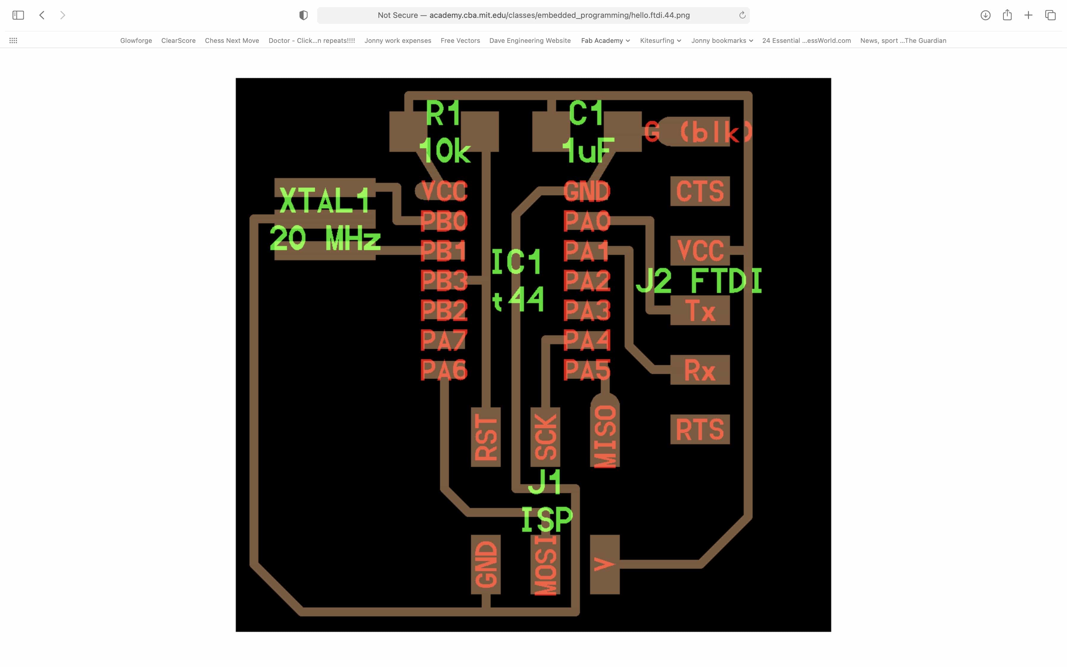
Link to ESP32 board design
All the design files for my custom ESP32 board are available for download in my Week 6 assignment:
Files for download
Link to the group assignment:
Back to homepage: