Week 11 - Input Devices
Assignment
individual assignment:
measure something: add a sensor to a microcontroller board
that you have designed and read it
group assignment:
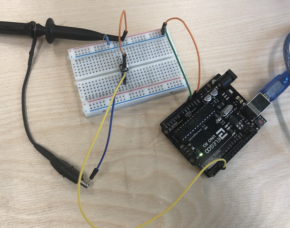
probe an input device's analog levels and digital signals
ESP32 board design
I spent the majority of this week re-making a new board using my ESP32 chip. I have documented this for my week 6 and 8 assignments. As a result, my work below looks rather sparse, but it took me a long time to get to the point that I could start testing my input devices!
You can check my board fabrication process in my week 6 assignment:
Problems and how I fixed them
I had many problems making my board and these are well documented in my week 6 assignment, linked above. As for the input devices, I'm pleased to say that everything worked just as planned, reading the input signals exactly as expected.
Digital and analogue inputs
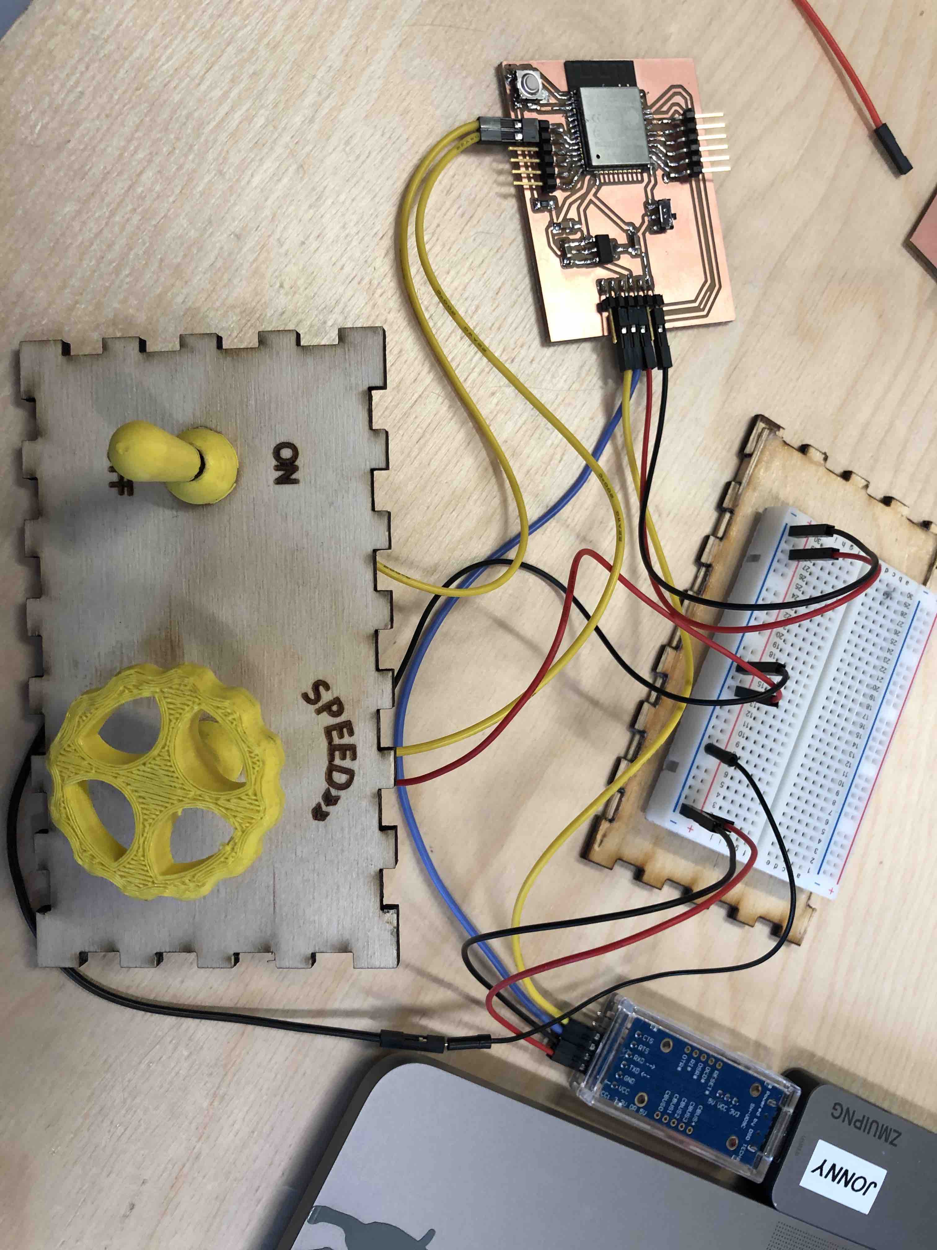
I've decided to add a simple button and potentiometer so that I can test an analogue and digital input. (I've re-used the controls from our marble run project) I've attached to 2 of the GPIO pins and I've used the internal pullup resistor for the switch.
The button has 2 wires. One wire goes to the GPIO input pin and the other wire is connected to ground. This means that when you switch it, you will connect ground to the GPIO input pin.
The potentiometer has 3 wires. One is ground and one is VCC. The middle pin is the signal pin and this wire is connected to the GPIO input pin.
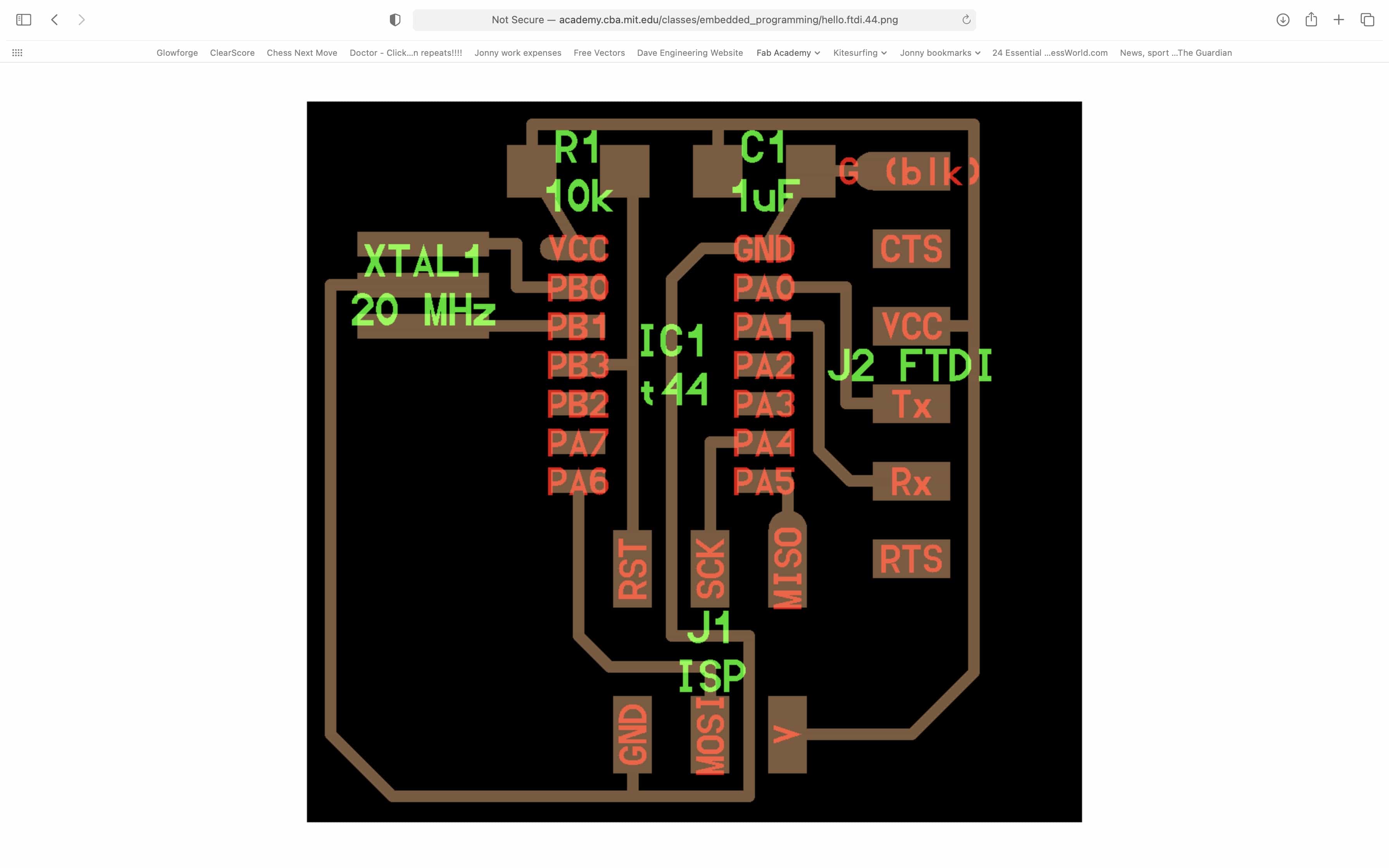
The FTDI programmer uses 4 wires. They are ground, VCC, TX and RX.
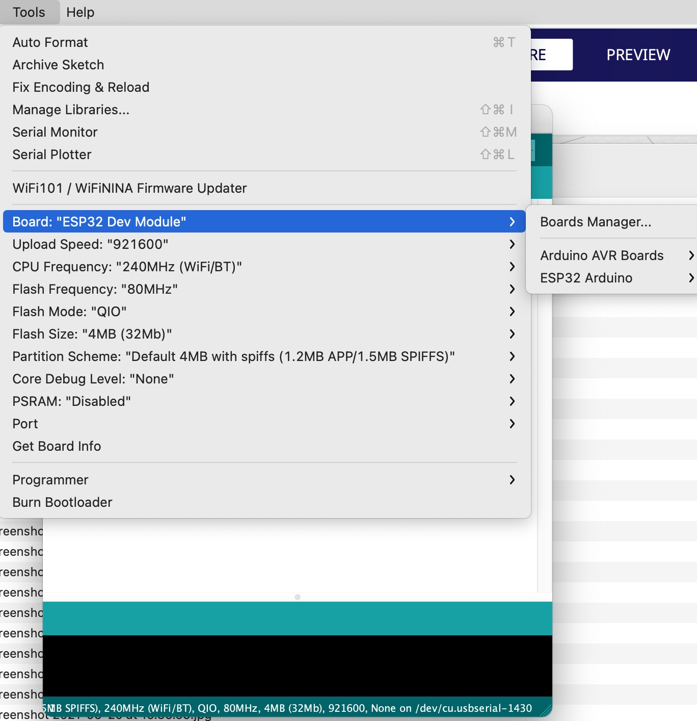
I'm using the Arduino IDE and an FTDI programmer that I bought on Amazon. Here is my code:
// Define pin connections & motor's steps per revolution


const int potPin = 12;    // select the input pin for the potentiometer
int potValue;
const int buttonPin = 33;
int buttonState;
int counter = 0;

void setup()
{
  Serial.begin(115200);
  pinMode(buttonPin, INPUT_PULLUP);
  pinMode(potPin, INPUT);
}

void loop()
{
  if (digitalRead(buttonPin)==0){
    Serial.println("Button pressed");
    potValue = analogRead(potPin);
    Serial.print("pot value is: ");
    Serial.println(potValue);
    delay(1000);
  } else {
    Serial.println("Button not pressed");
    potValue = analogRead(potPin);
    Serial.print("pot value is: ");
    Serial.println(potValue);
    delay(1000);
  }
}
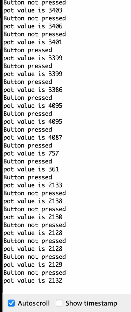
I can view the inputs on the serial monitor and can see that both the button and potentiometer are working correctly.
Physical property vs measured results
Button:
My button was in one of 2 physical states, on or off. I have used an internal pullup resistor on the ESP32 by setting the input in my code with 'INPUT_PULLUP'. As a result the input pin will always read high and if read its value, it will give me the number 1. When I press the button, it connects the pin to ground which will read low, thereby giving me the number 0.
Potentiometer:
My potentiometer is analogue and can be set anywhere across a range of 270 degrees. At 0 degrees it will output 0 and at 270 degrees it will output 270. Between 0 and 270 degrees it will output a value between 0 and 4095, in direct proportion to the number of degrees you have turned.
Input device readings
| Input device type | Physical state | Input reading |
|---|---|---|
| Digital button | 0n | 1 |
| Digital button | Off | 0 |
| Analogue potentiometer | Turned fully anti-clockwise | 0 |
| Analogue potentiometer | Turned fully clockwise | 4095 |
Files for download
Link to group assignment
Back to homepage: