
Final Project
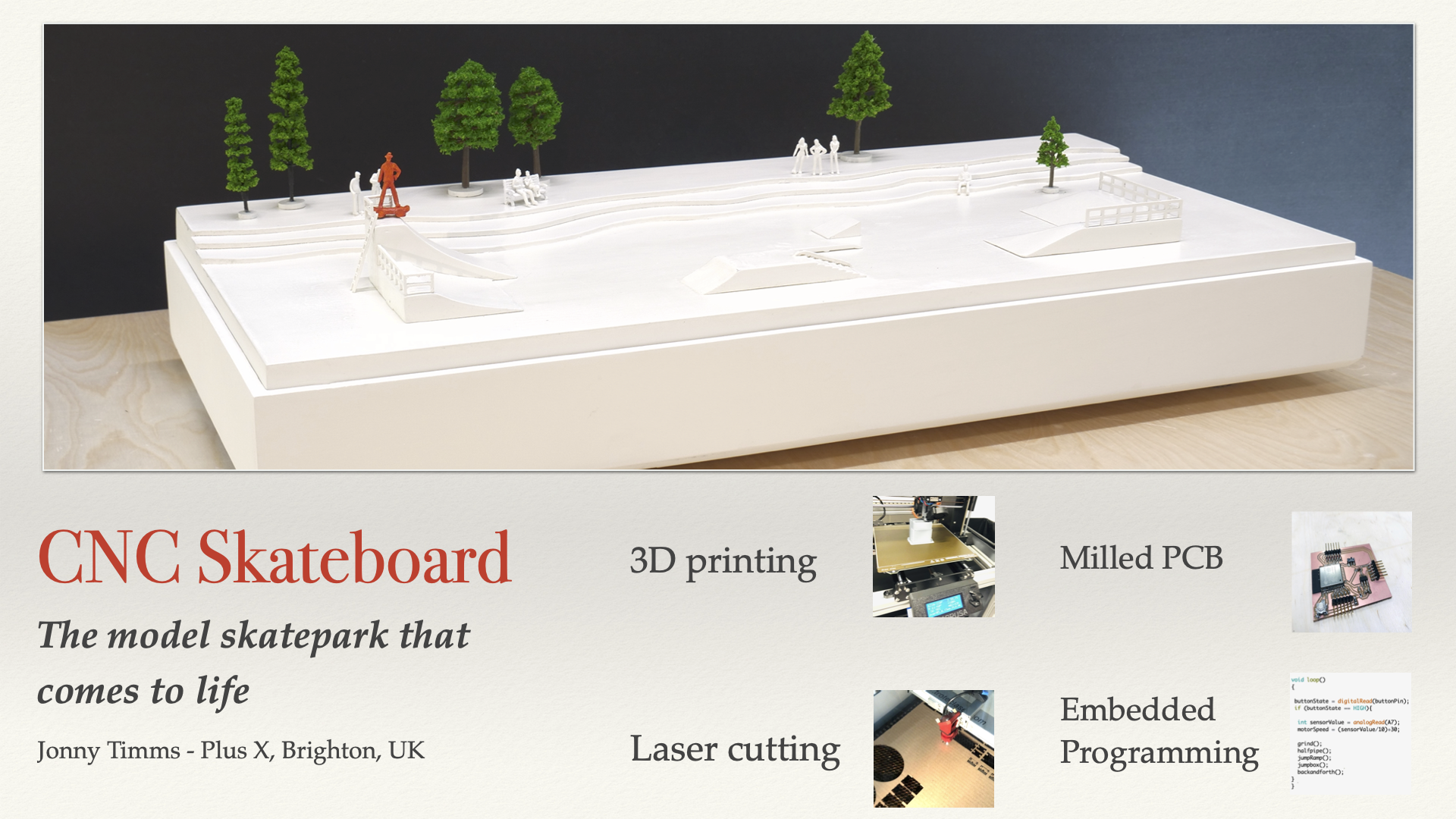
CNC-style model town
My idea is to make a small model town with a CNC-style machine beneath it. The machine would move a magnet around the town and could move objects such as cars, trains, skateboarders, people mowing their lawn etc. My idea was inspired by three things.
Inspiration 1 - Adrian Torres Fab Academy Train Model
This was a great example of simple project well executed. It met the 3 criteria from the youtube series 'How to survive Fab Academy':
1 - It is simple
2 - It is beautifully made
3 - It has a clear function or purpose

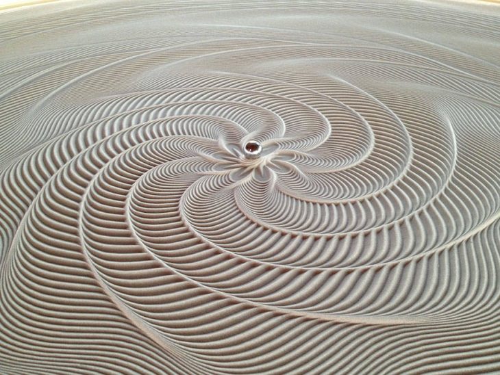
Inspiration 2 - Sisyphus table
I saw this product on youtube and thought it was such a great idea. The magnet is mounted on a set of rotating discs beneath the table and it moves a steel ball across circular patterns through the sand.
 https://www.youtube.com/watch?v=Ztax9lCE-Mk
Inspiration 3 - Architectural models
My dad was an architectural model maker and so I grew up watching him make beautiful scale models. Sadly I don't have a photo of his models available but I found a good example of a model town. This one is made by ModelMakers Ltd:

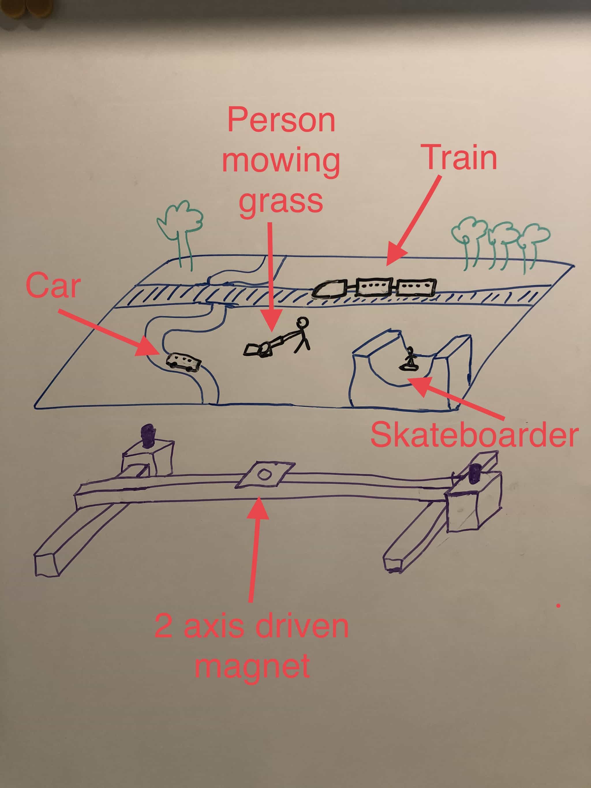
Combining these 3 ideas
I'm imagining a model town like the image above, but with a CNC-style 2 axis machine beneath it. A magnet in place of an extruder would move objects around the model. Here is a basic sketch of my idea:
What will it do and who will use it
My project will move objects around a scale model with tremendous precision. It is not intended as a commercial product and so its use is really as an art piece and/or educational tool. I am hoping it will prove to be an exciting project that allows me to learn and apply all the skills of the fab academy course.
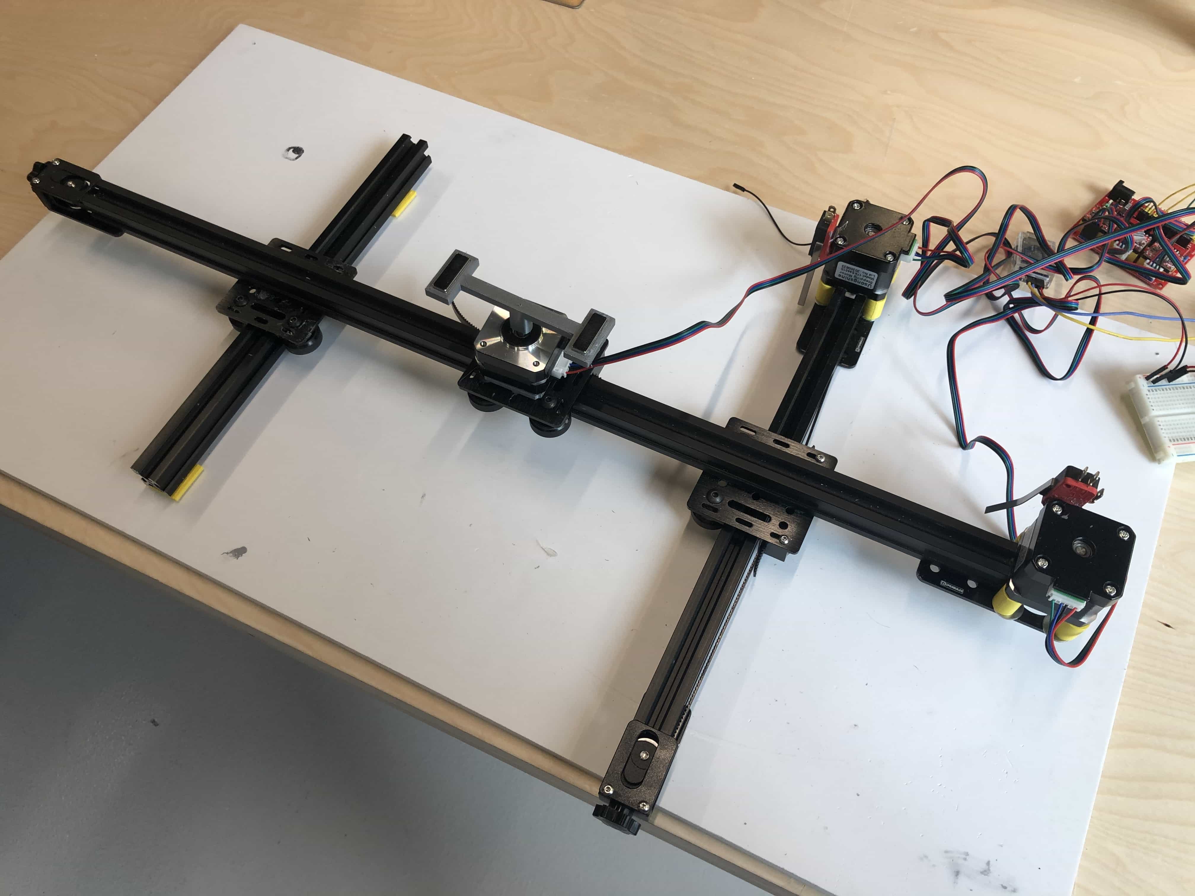
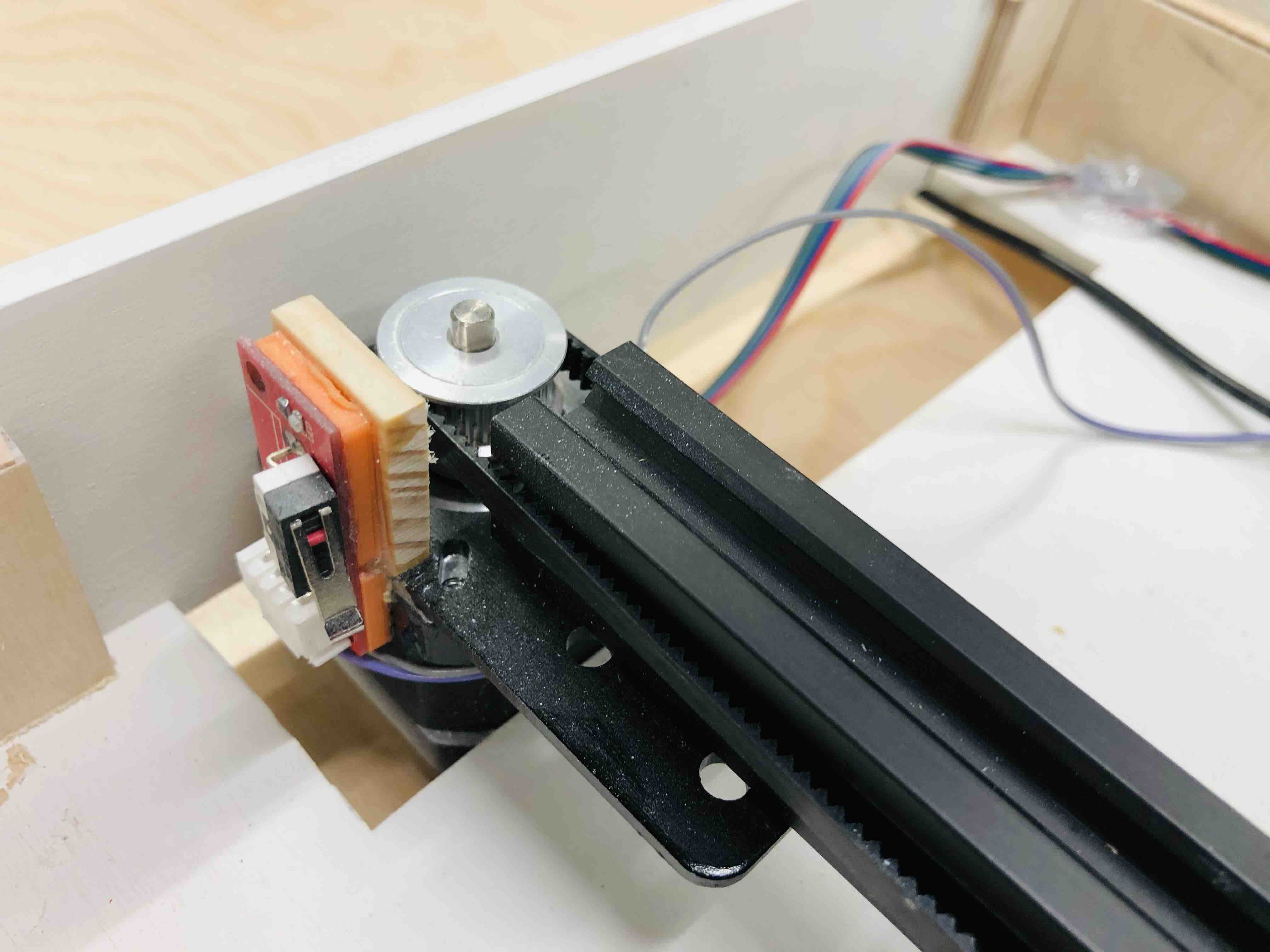
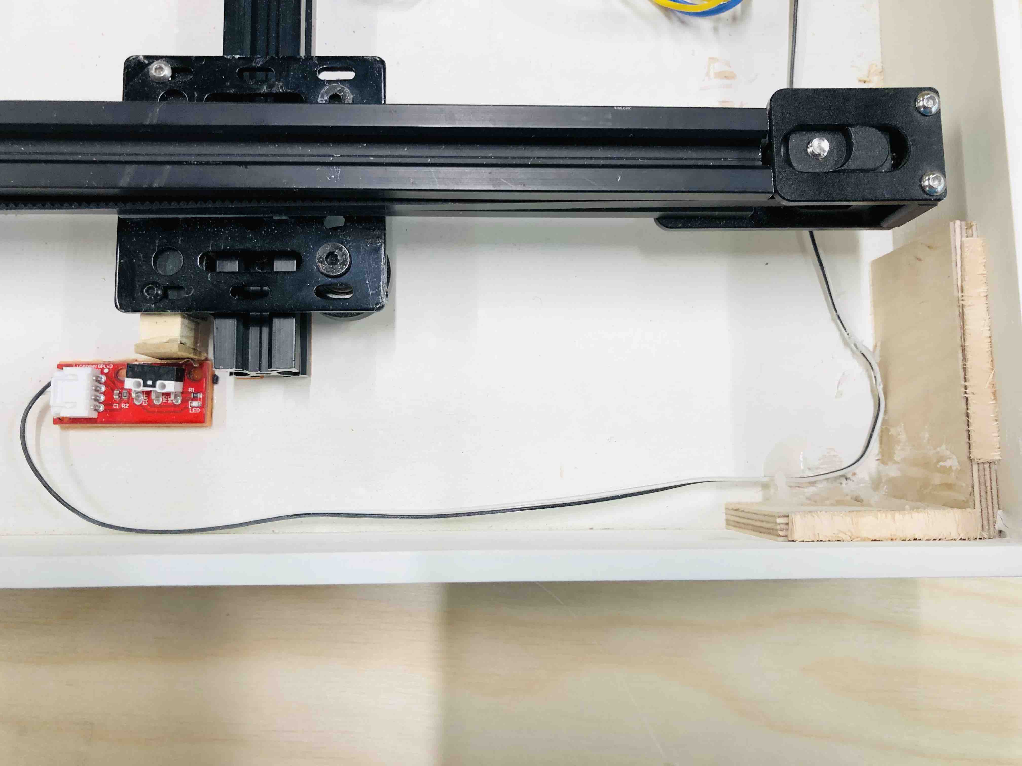
Quick prototype to test concept
I've written some basic code and set up a magnet on a single axis roller. A miniature skateboard with magnets attached is placed on top of some 3mm plywood.
Here are 2 short videos that shows the skateboard being moved by the magnet. It seems to work reasonably well and is kind of fun.
Features
I can get a little carried away with adding too many things to a project and so I decided to make a quick list of potential features and give each a score out of 10, firstly for how much fun the feature would be and secondly, for the level of complexity. By complexity, this is my attempt to take a view on how much time and/or stress may be required. By subtracting the complexity from the fun, you get an overall score. I then rank the features in order and start at the top.
Features by score
| FEATURE | FUN FACTOR | COMPLEXITY | SCORE |
|---|---|---|---|
| 2nd axis (Y) | 7 | 4 | 3 |
| Board slide | 8 | 6 | 2 |
| Power slide | 7 | 3 | 4 |
| Quarter pipe | 7 | 7 | 0 |
| Half pipe | 8 | 8 | 0 |
| 180 | 6 | 4 | 2 |
| Jump ramp | 8 | 6 | 2 |
| Grind | 5 | 7 | -2 |
| Stair jump | 8 | 7 | 1 |
| Stair rail slide | 10 | 7 | 3 |
| Nose slide | 7 | 8 | -1 |
| Tail slide | 7 | 8 | -1 |
| 3rd axis (Z) | 9 | 10 | -1 |
| Olly | 10 | 10 | 0 |
| Game control | 8 | 9 | -1 |
| Car pull | 7 | 10 | -3 |
| Cone dodge | 4 | 3 | 1 |
| Jump box | 6 | 5 | 1 |
| Untitled |
Week 11 - Input devices
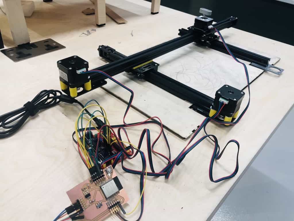
This week I have added a 2nd axis to the model.
I've also replaced the esp32 module bought from Amazon with my own custom esp32 board. I'm using my 2 input devices for this week, the switch and potentiometer, to engage the machine and also to control the speed.
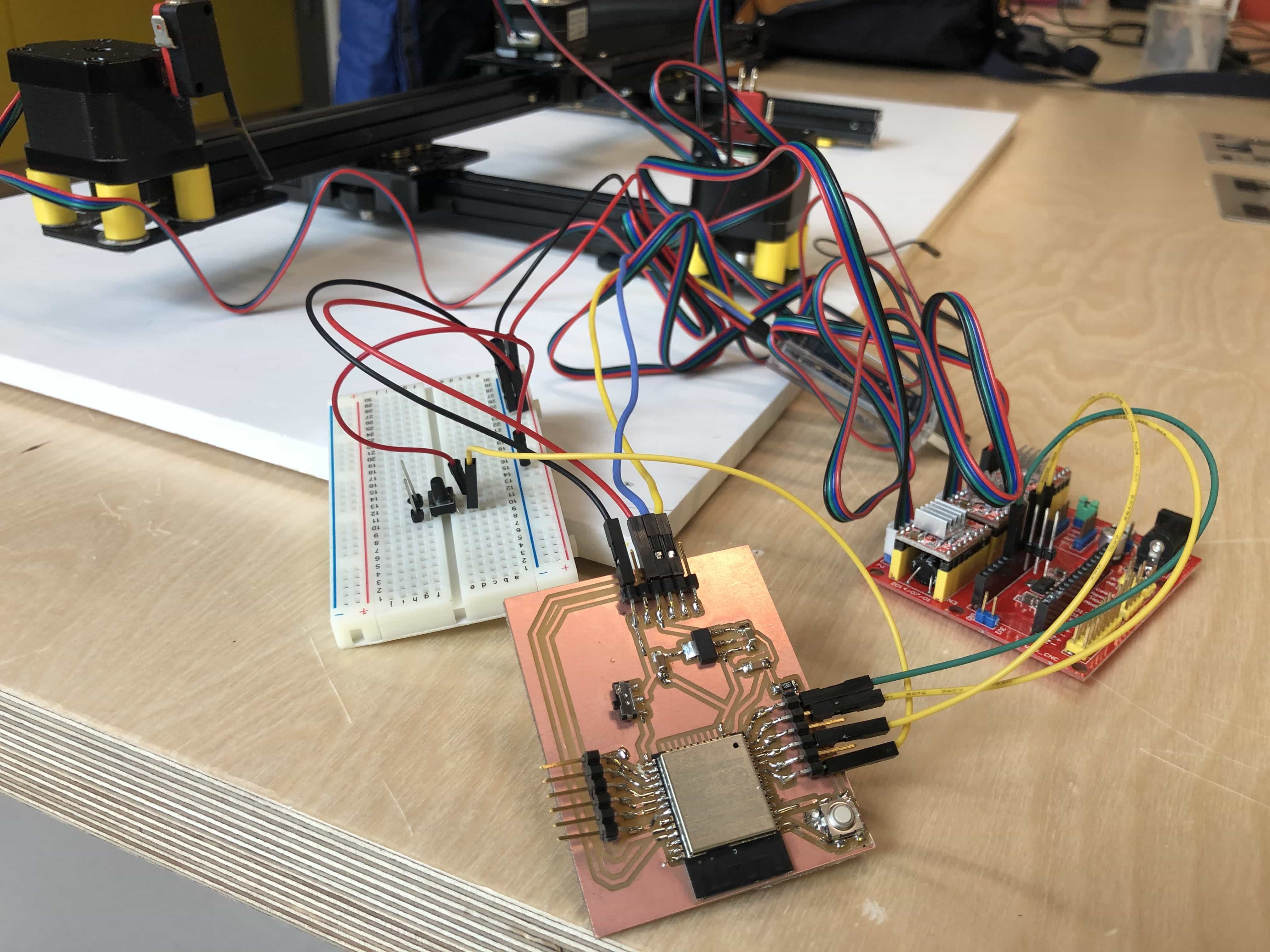
I'm pleased to say that my custom esp32 board is working great. Sadly I have burned out my motor drivers and I'm now waiting for my delivery of new drivers. Video to follow after they have arrived...
Noise problems with the mechanical assembly
The entire assembly is noisy and clunky during operation. I've identified the following issues and have managed to find solutions for all...
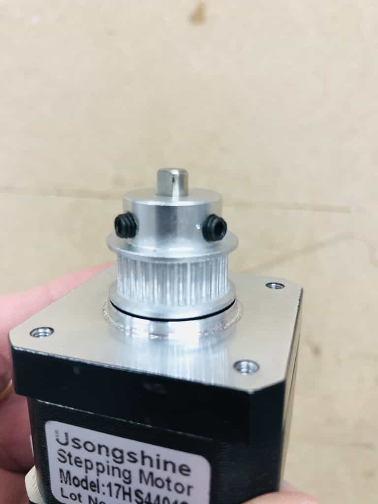
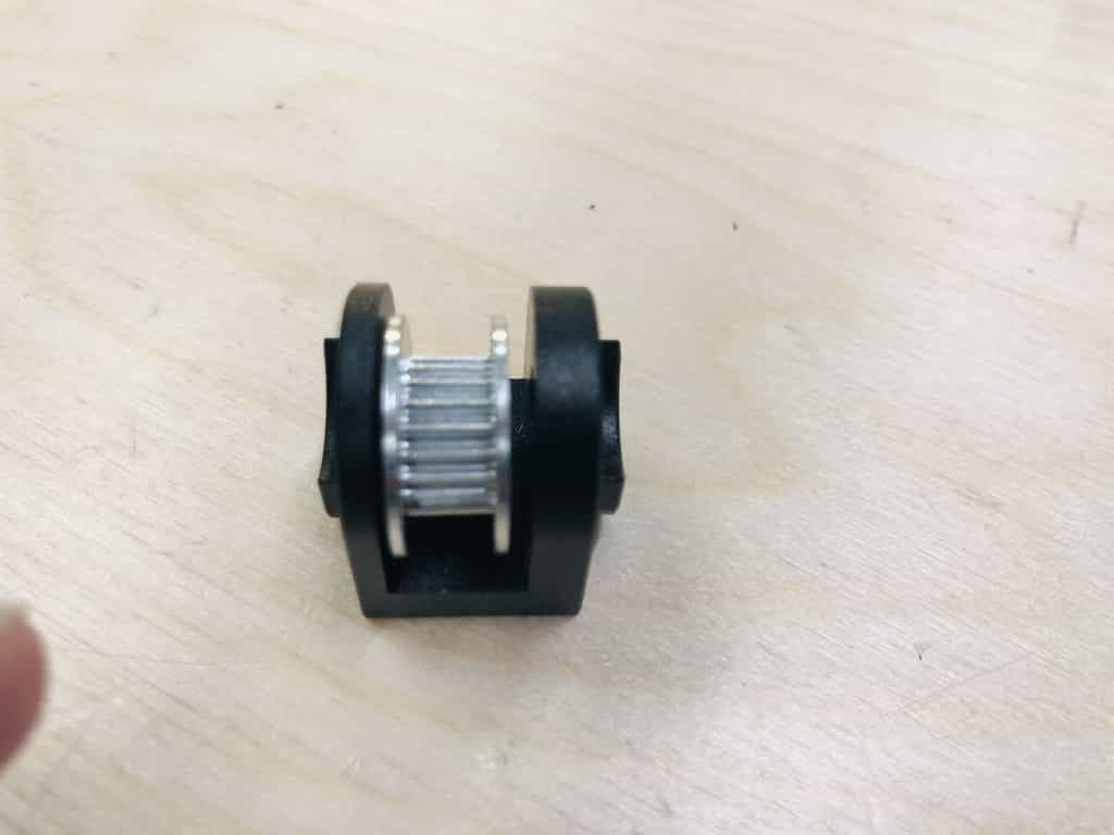
Problem 1 - Motor pulley too close to the motor surface
Solution - I raised the motor pulley just a fraction of a millimeter. This reduced a lot of noise where the metal of the pulley was grinding against the metal of the motor surface.

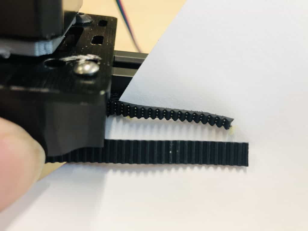
Problem 2 - Belt is too wide for my design
My belt should be 6mm but it is actually 6.2mm. As a result there is friction when I try to fit inside the 6mm gap of the aluminium extrusion. I'll probably buy a 5mm belt but I wanted an immediate solution and so I cut it down with a Stanley knife.
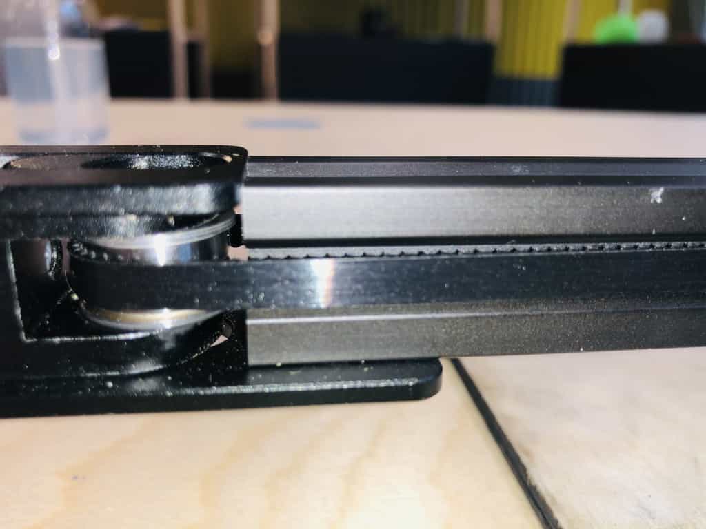
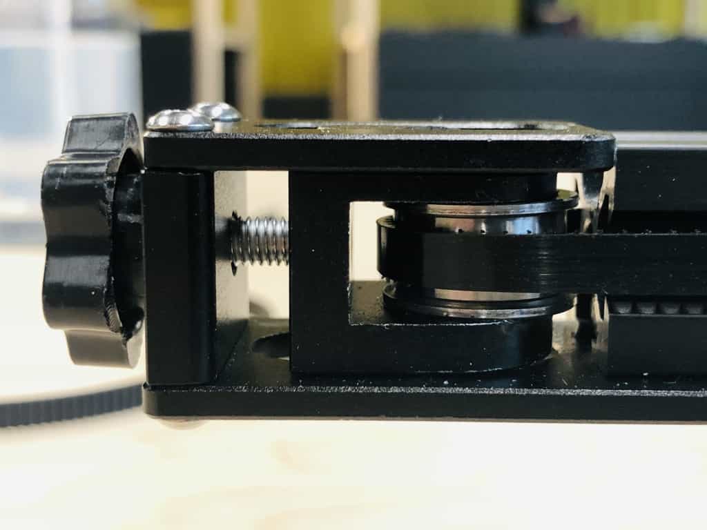
Problem 3 - Pulley is rubbing on the metal tensioner
Week 13 - Output Devices
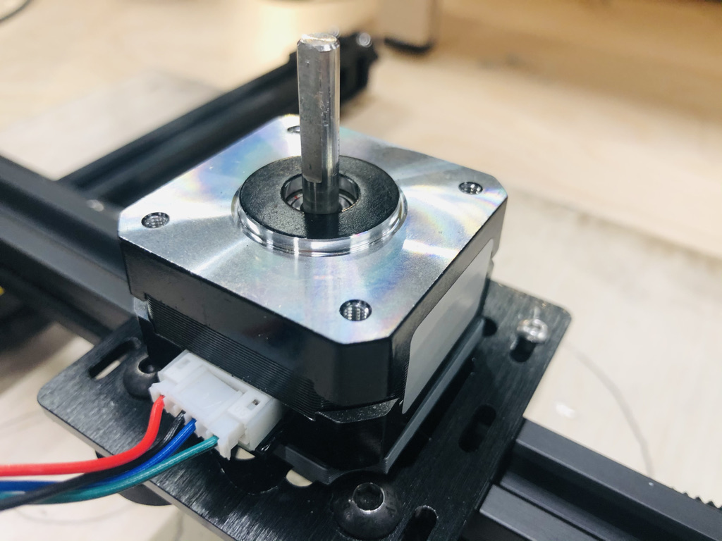
Stepper motors
This week I will be almost completely focussed on stepper motors. I already have 3 stepper motors on my project and technically, they all work. The problem is that they're noisy and jumpy.
My goal for this week is to get all 3 stepper motors on my project, working in harmony and with minimal noise. My motors are all NEMA 17, two of them with 1.7A rated current and another smaller version with 1A rated current.
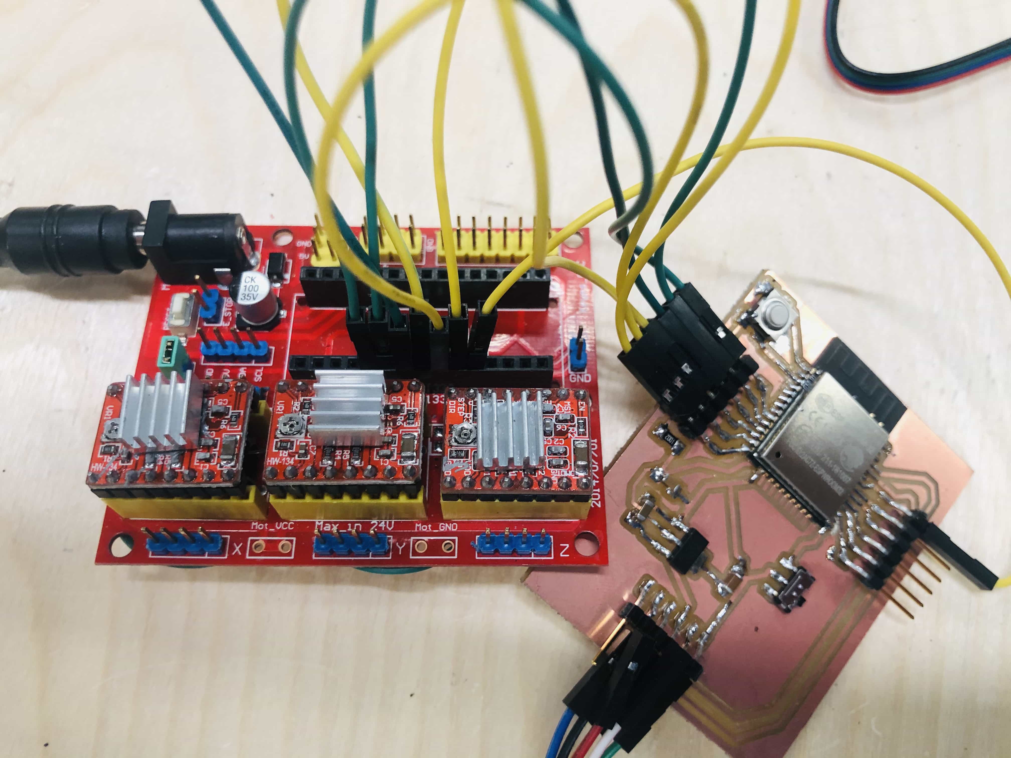
Stepper motor drivers
The first drivers I've used are the A4988. Here they are loaded up on my CNC shield:
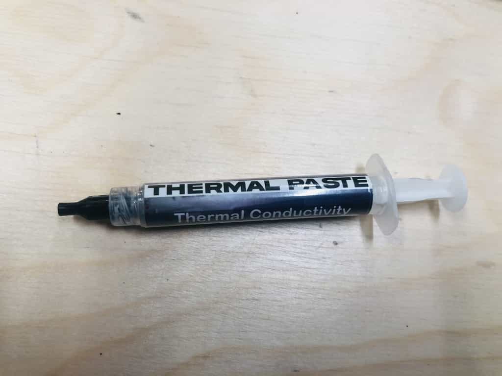
Thermal paste
I've had issues with these drivers over-heating. So far I've blown 6 of them and so after a little research, I found some advice to use thermal paste. I bought a one part version on Amazon but a lot of people were recommending a 2 part version which was not easily available in the UK.
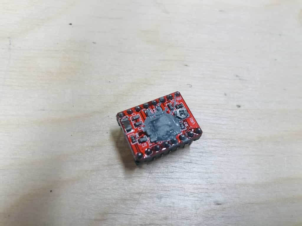
Its way too much. I thought it would stay in position on the chip but it is less viscous than I thought.
Don't do this
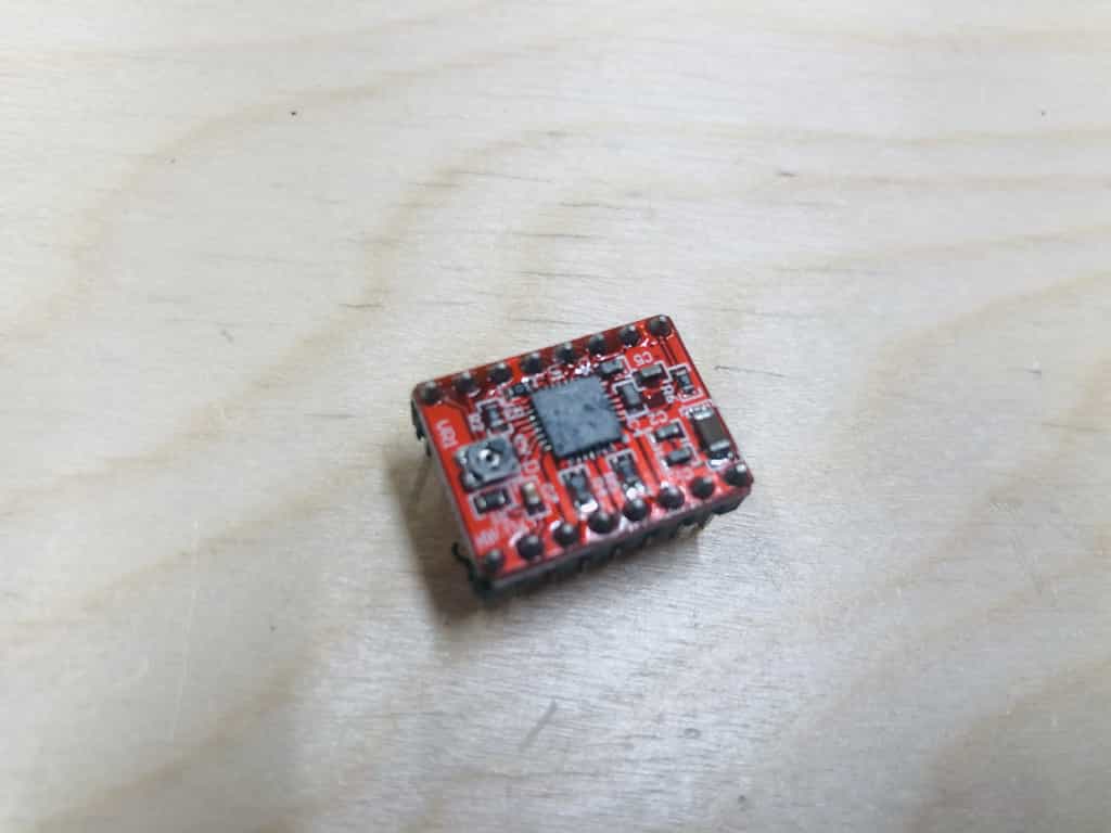
Do this
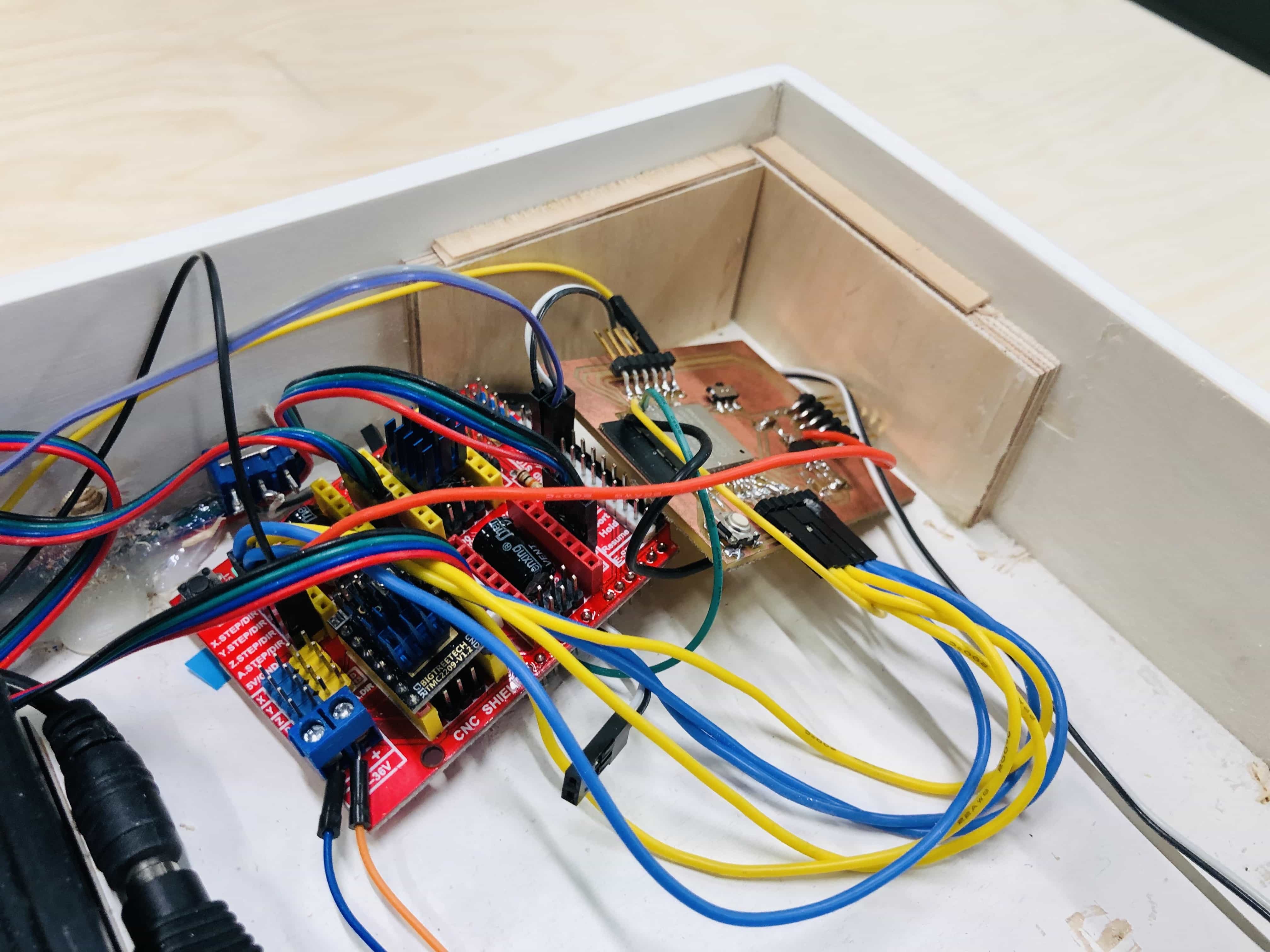
ESP32 board with CNC shield and A4988 drivers
I'm ready to go with this configuration. I've used thermal paste which I'm hoping will help prevent the over-heating I experienced previously:
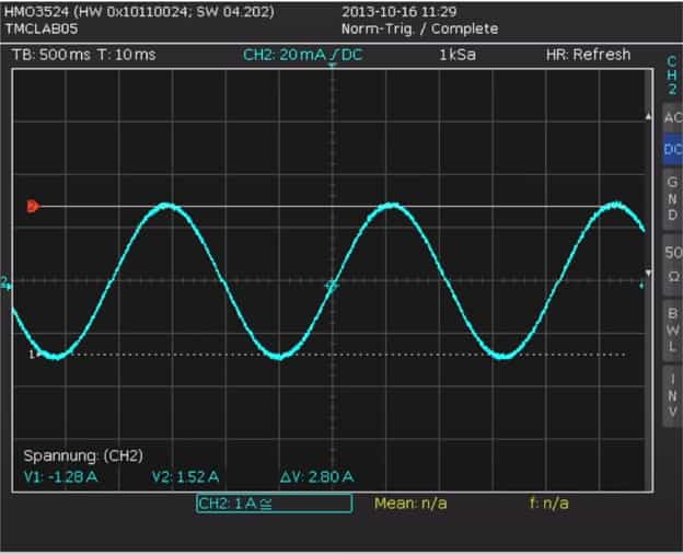
Setting the current for each motor
Each A4988 driver has a potentiometer which allows you to limit the current passed to the motor. The formula to calculate
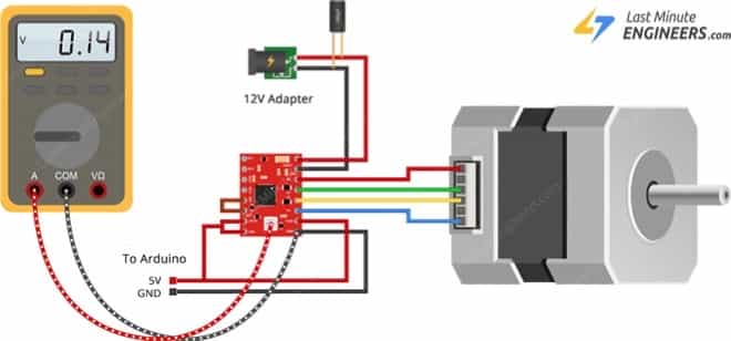
There is a simple formula that allows you to calculate the Vref value:
My larger motors are rated at 1.7A and my smaller motor is 1A. I shall substitute these values into the equation above:
Larger motor(1.7A) - (The vref value should be 0.68 volts)
Smaler motor(1A) - (The vref value should be 0.4 volts)
This isn't a great photo because I'm working alone and can't photo the actual process. You need to check the voltage by pressing the red lead to the potentiometer and the black lead to the ground pin on the chip. You turn clockwise to reduce the voltage and anti-clockwise to increase it. You need to keep adjusting and checking the voltage until you get the values above.
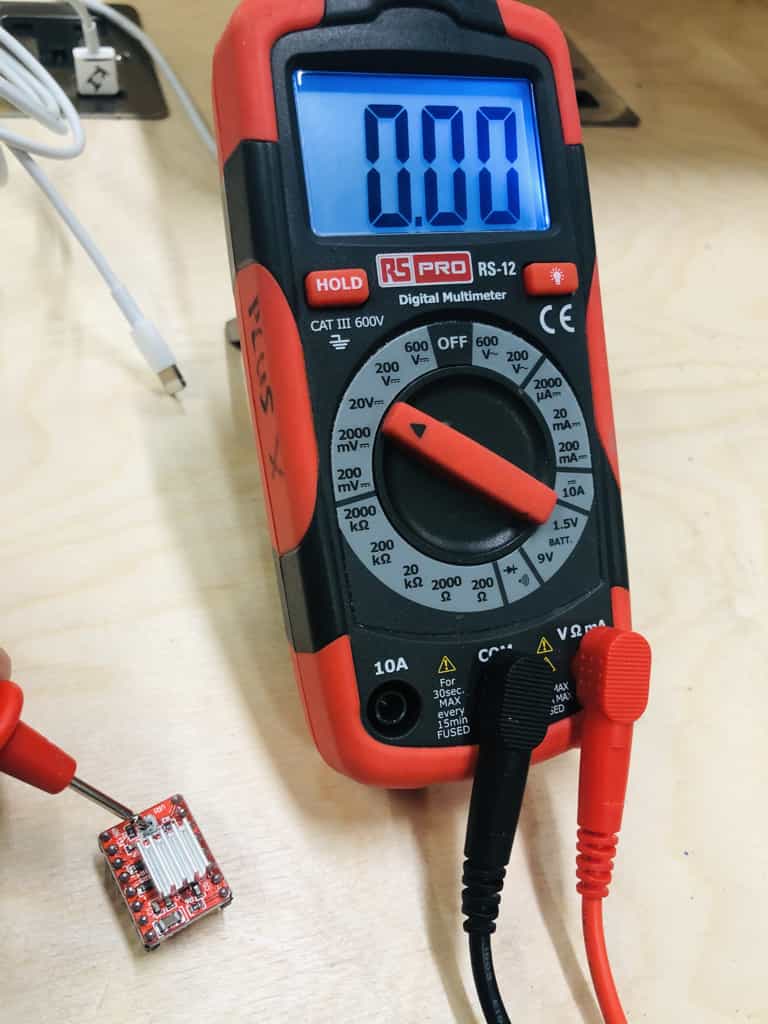
The easiest way for this process above is to attach a crocodile clip from the multimeter onto a screwdriver. Then you can read the voltage while you make the micro adjustments.
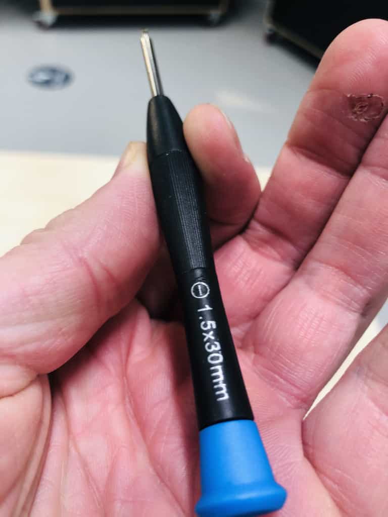
Correct screwdriver
I considered this important enough to give it a title! I tried more than 10 different screwdrivers on the small potentiometer and none of them would make a good connection. As a result of using a poorly connecting screwdriver, I repeatedly damaged the potentiometer. If you keep screwing it with the wrong screwdriver, it eventually falls off and the driver is useless.
I bought a new set of micro screwdrivers and surprisingly, the only screwdriver that would work was a flat head screwdriver of 2mm. Its a bit of a red herring because the screw has a crosshead but I could not make it turn with anything other than a flat head 1.5mm.
Here it is, the only screwdriver in the world that can adjust the potentiometer on these drivers:
Noise levels with stepper motors
The following 3 videos show the same movement each time, but I've changed the motorspeed in video 2 and changed the driver in video 3. In each video I do the following:
- Moves both ways along the X axis
- Moves both ways along the Y axis
- Moves simultaneously along X and Y axis in both directions.
Video 1 - Regular drivers at regular speed
I've been using a delay of 100 microseconds between engaging the step pin on each motor. So I've kept the speed at what I thought would be the same, with 100 microseconds between every step.
INSERT VIDEO 1 HERE
Video 2 - Regular drivers at half speed
Now it turns out that when I try and move both motors together, I've doubled the length of time between steps. The reason is that the microprocessor has to go and move the other motor 1 step in between every step. The result is that the speed is half what you expect. I've corrected this by halving the delay and this video is a great demonstration of how the speed of a motor can affect its noise.
INSERT VIDEO 2 HERE
Video 3 - Trinomic drivers in Stealth Chop mode
Now I'm using the SilentStep drivers from Trinamic. There is a mode called Stealth Chop which gives near silent operation.
INSERT VIDEO 3 HERE
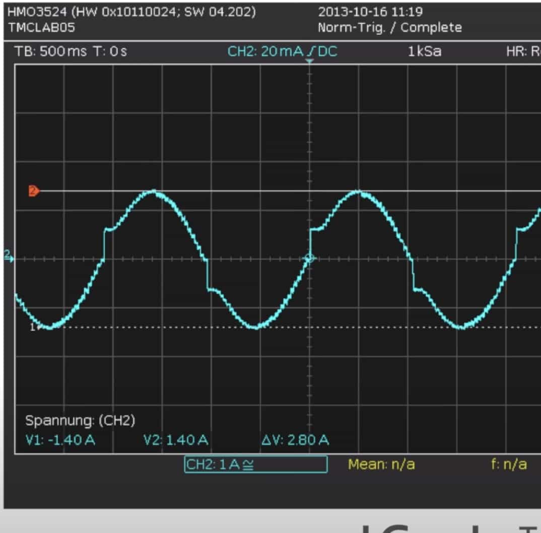
Stealth chop - how do they do it?
This screenshot from their youtube video shows how their drivers smooth out the current between steps:
2D design
I've used both Adobe Illustrator and the sketch environment in Fusion 360 for my 2D design. The main base will be made from plywood and it has cut-outs that allow the motors to move up and down. There are also holes that are used to mount the aluminium rails.
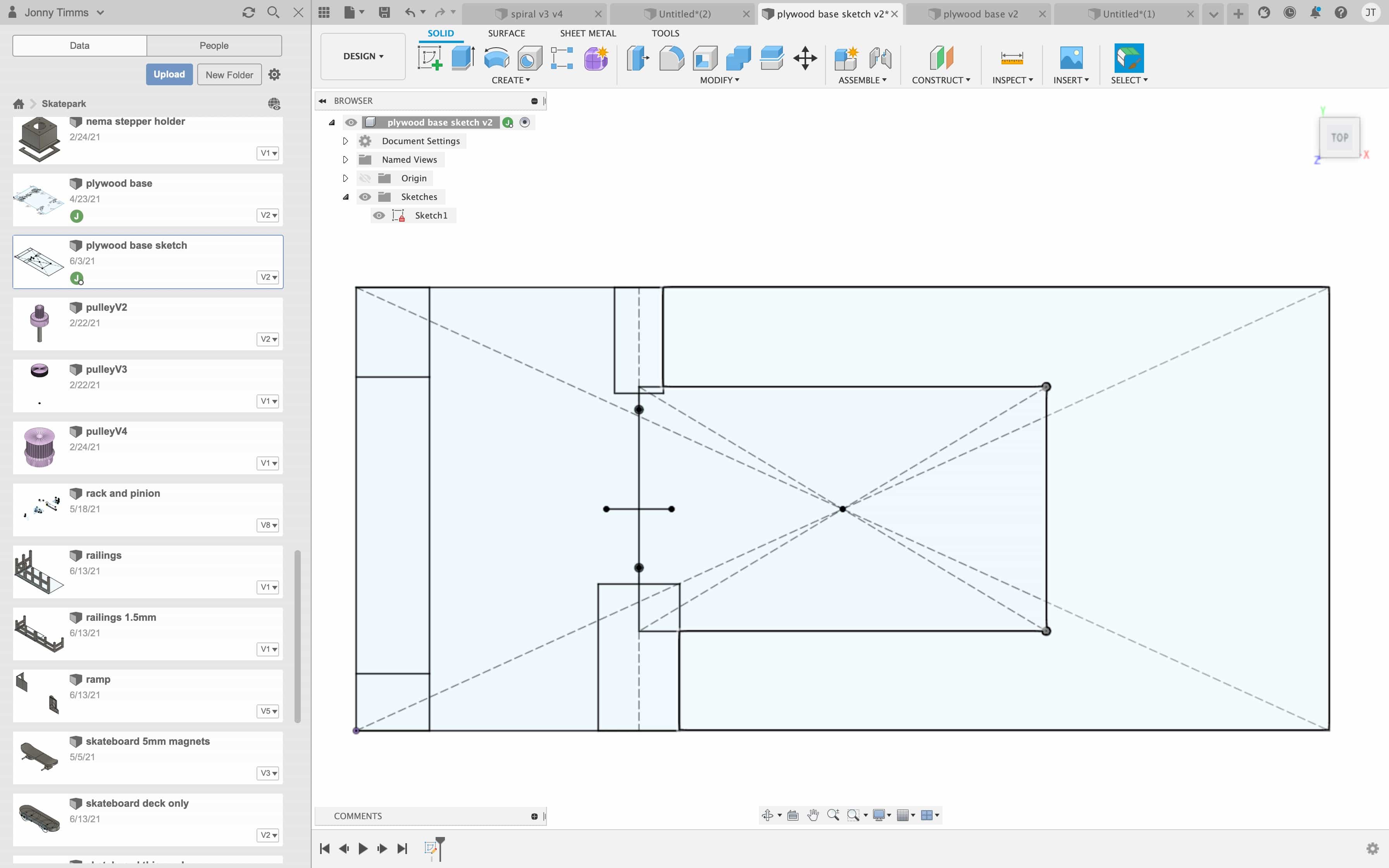
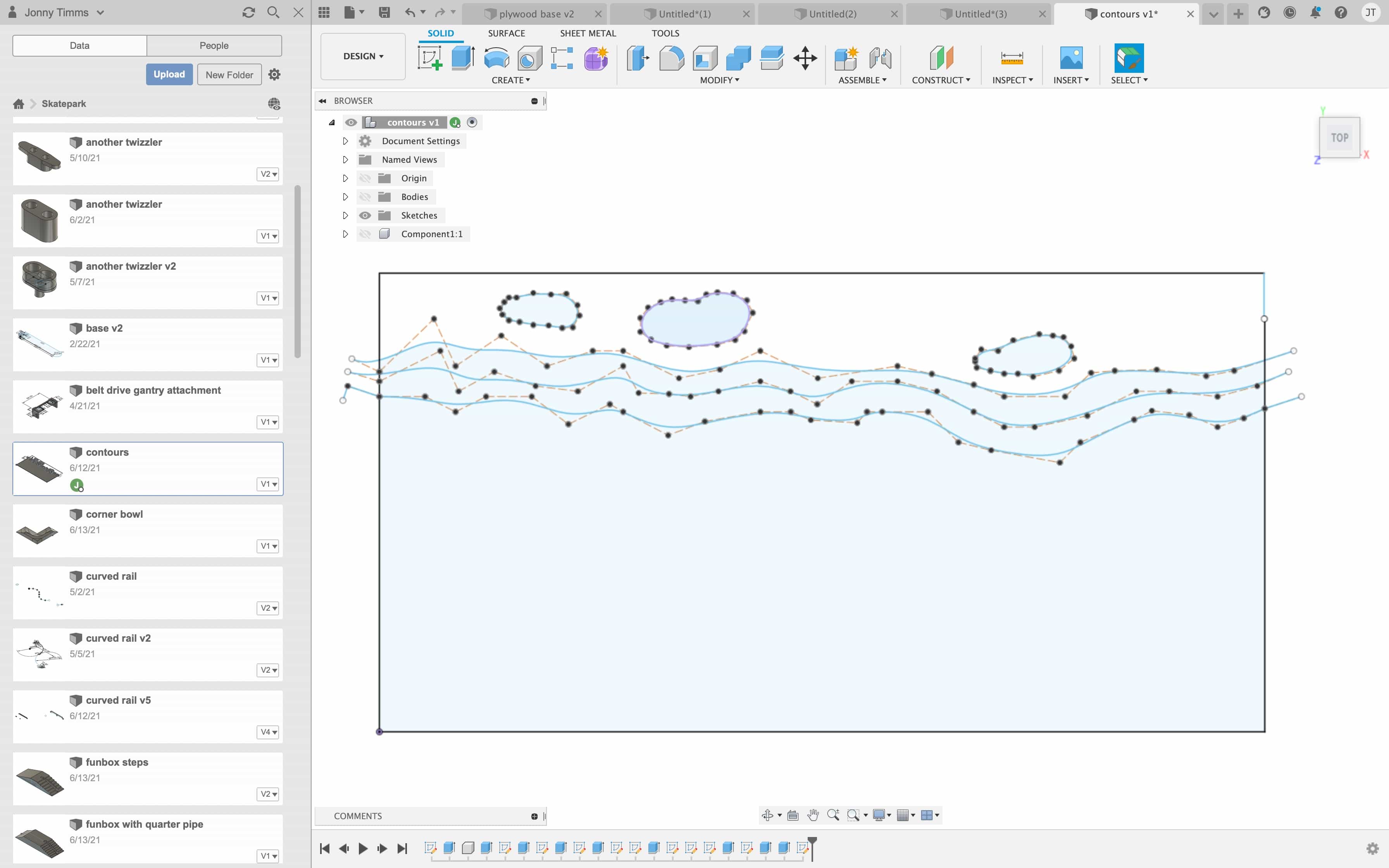
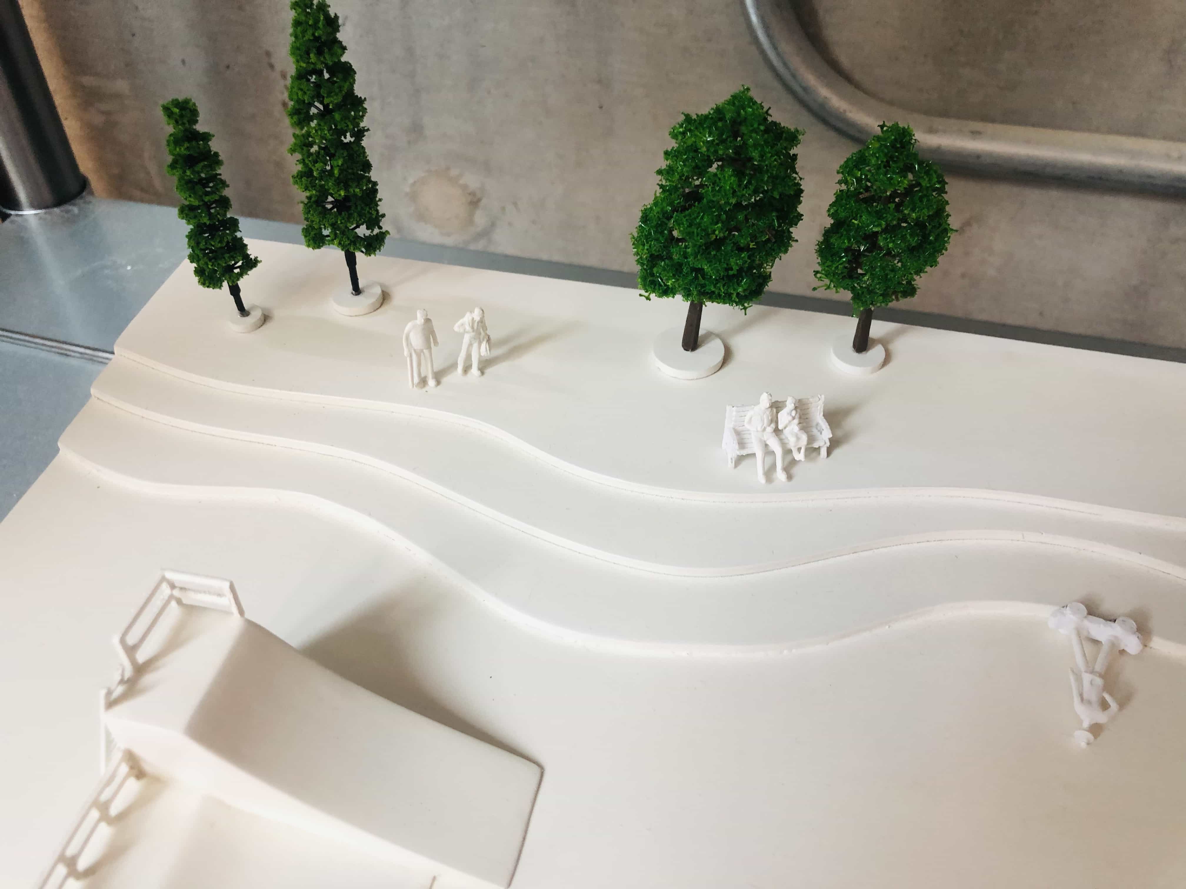
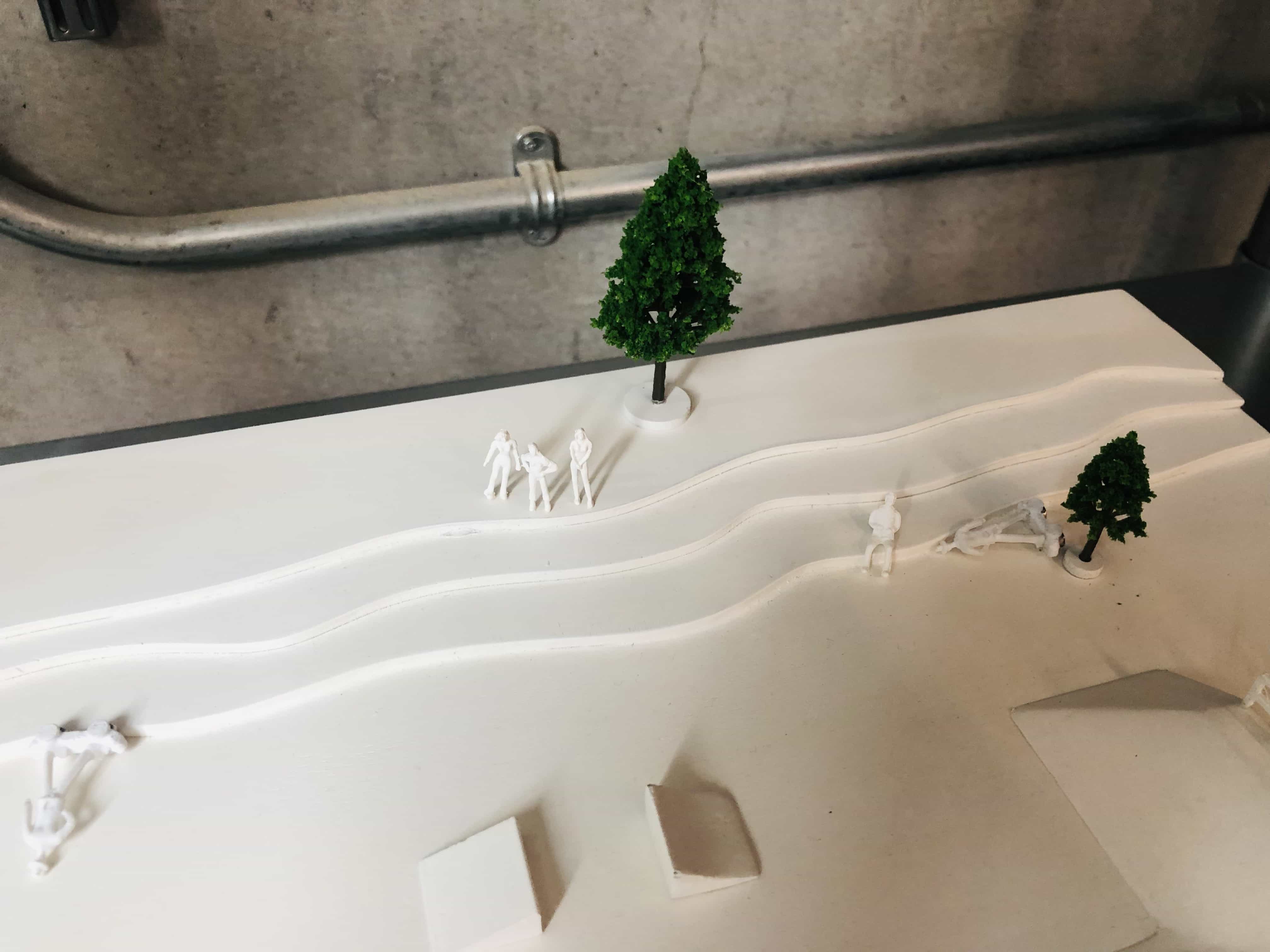
I wanted to add some contours to the model. I chose to use the spline tool in Fusion 360 and this worked really well:
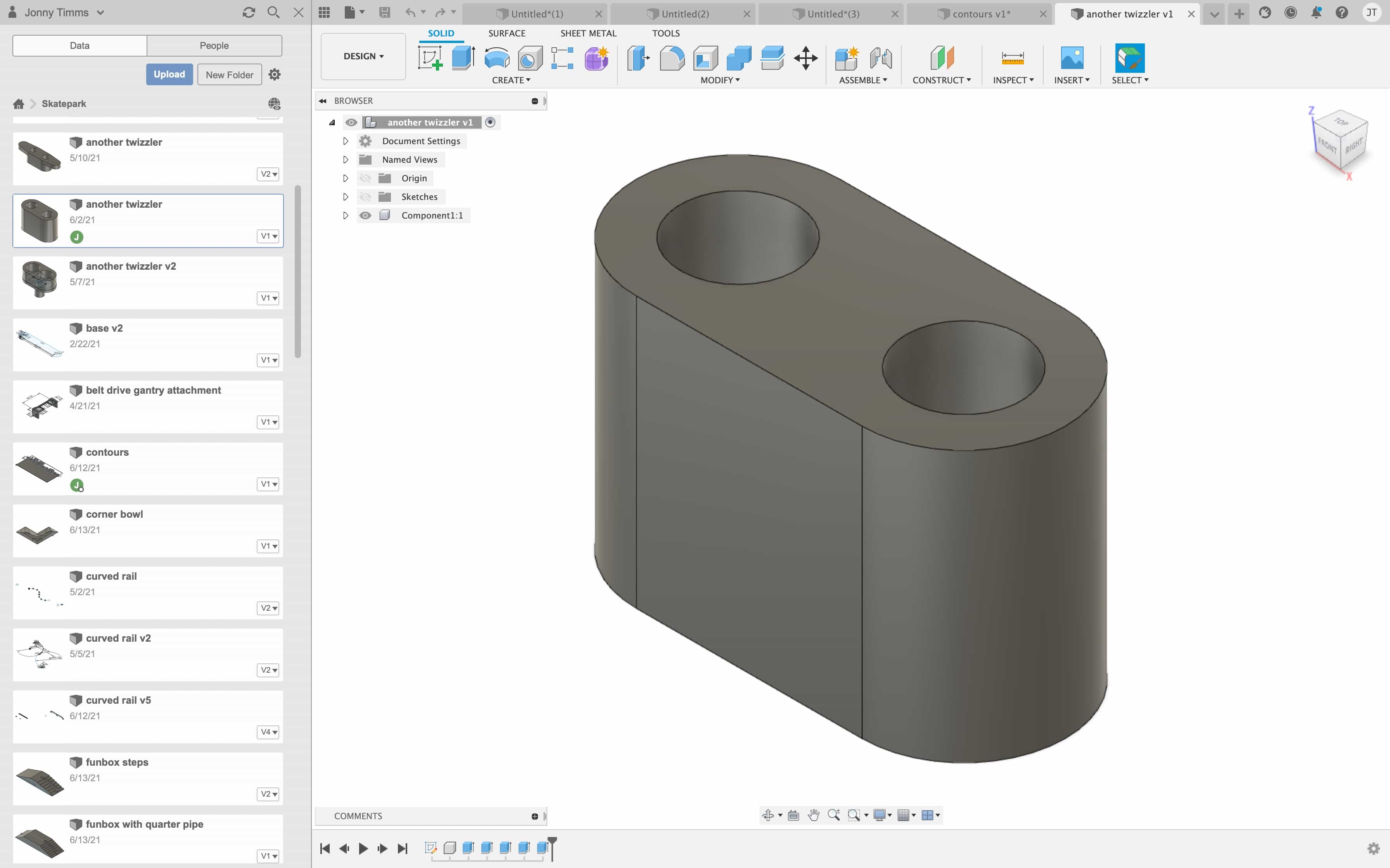
3D design
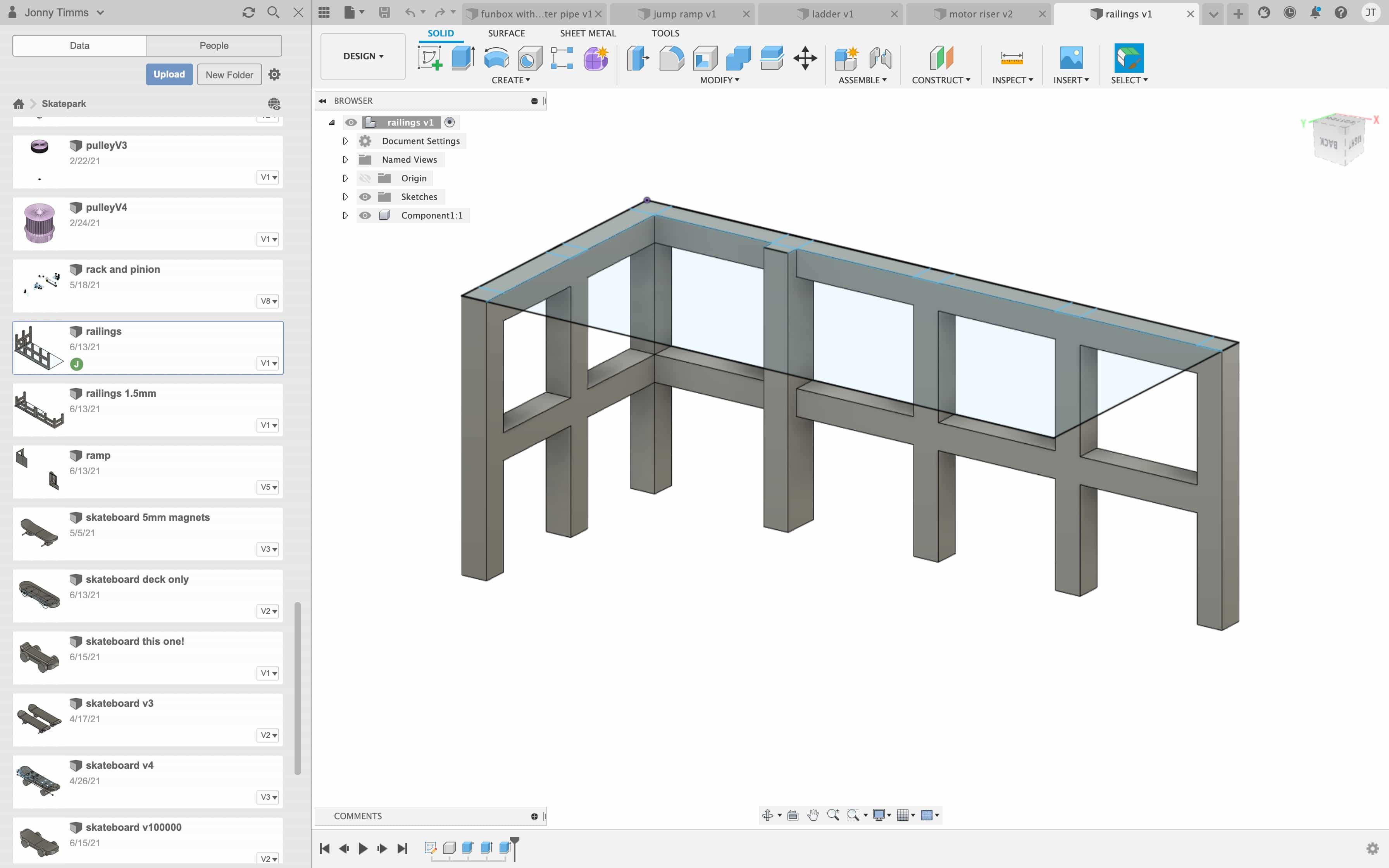
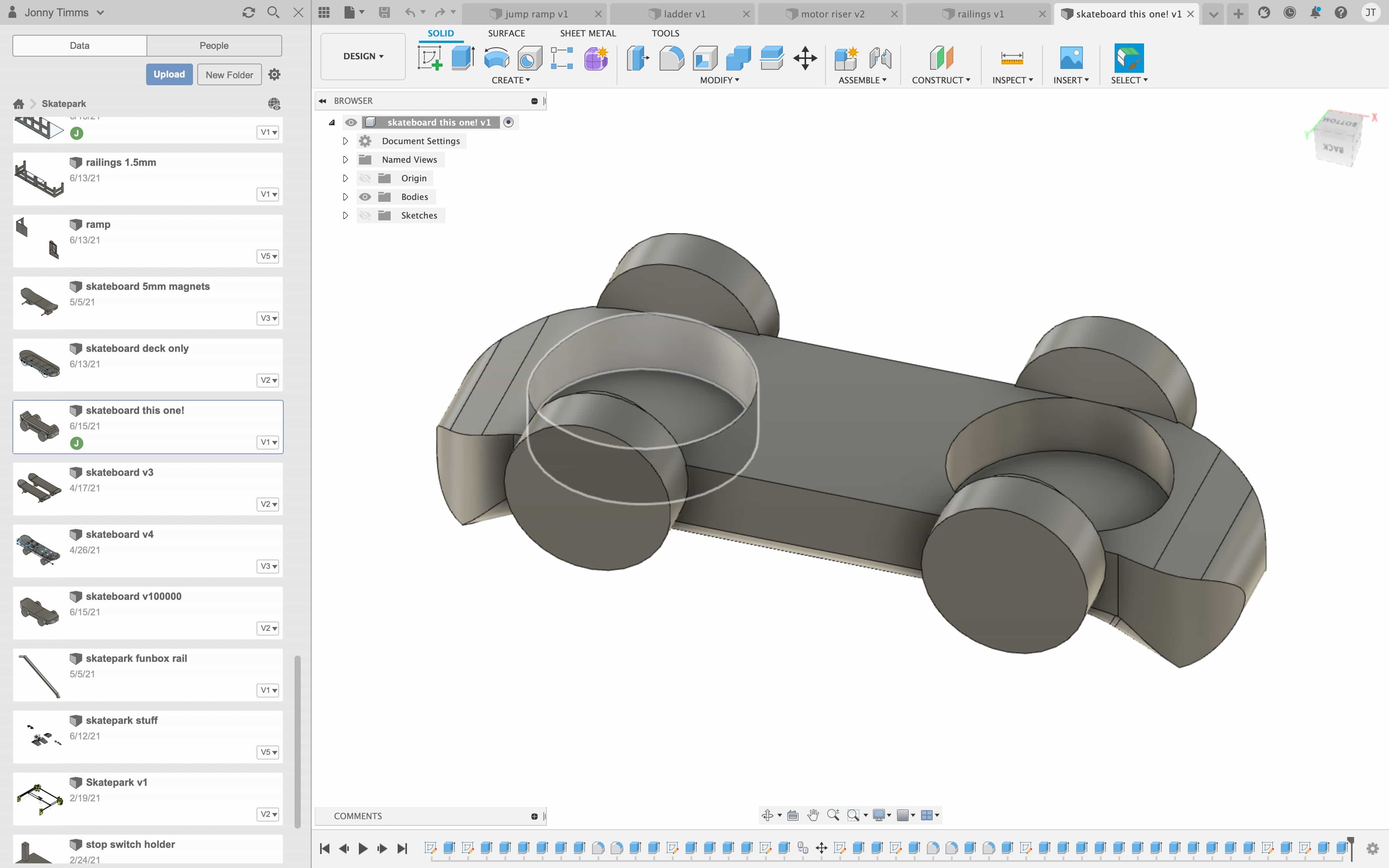
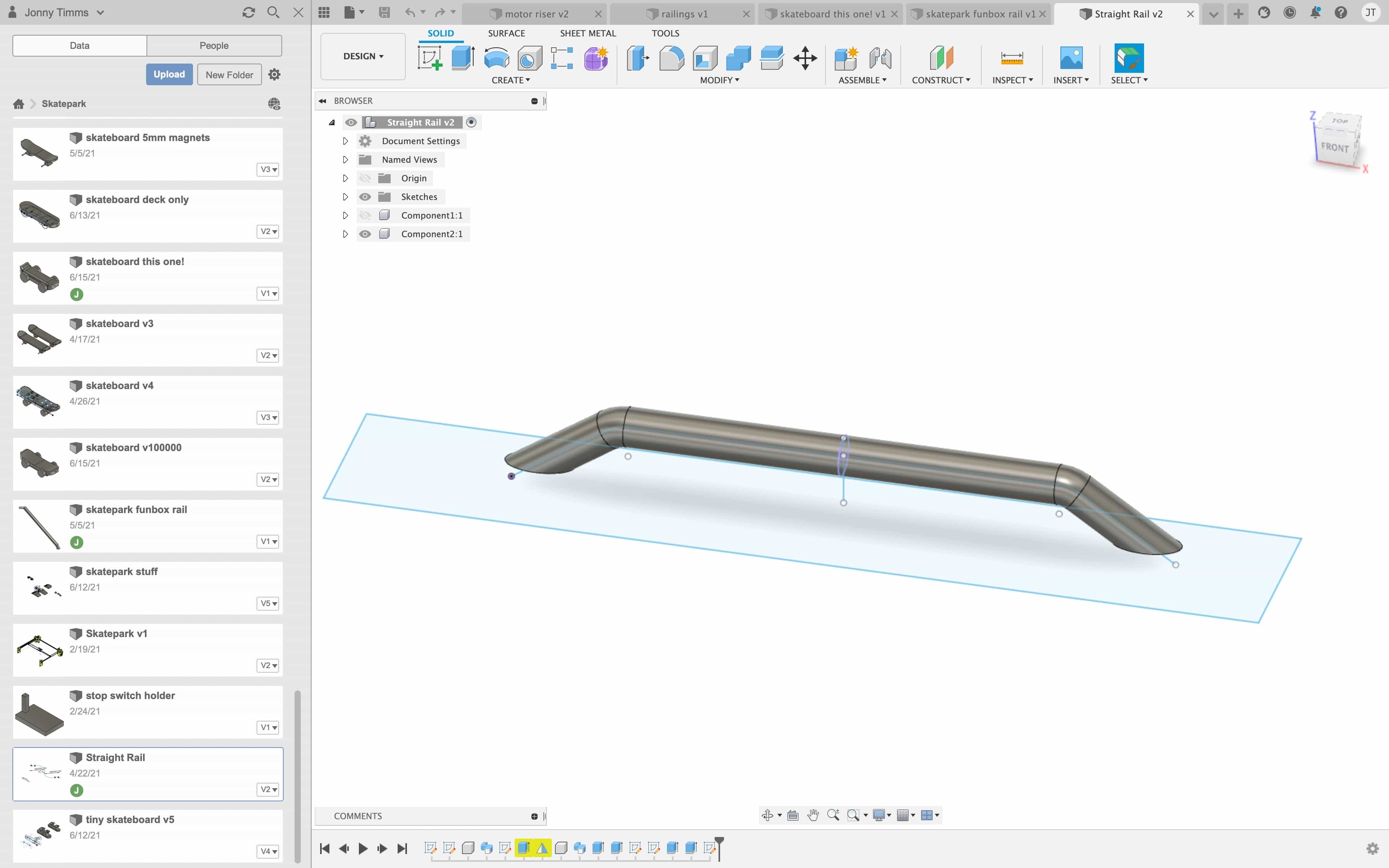
I've designed the skatepark obstacles using Fusion 360. I spent a lot of time testing different sizes and shapes, to understand which designs would function best with the skateboarder.
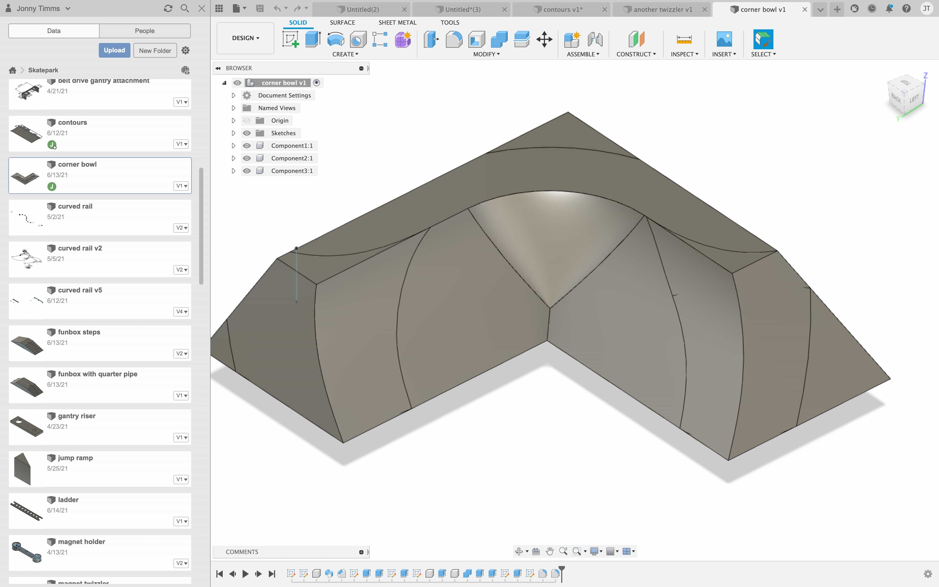
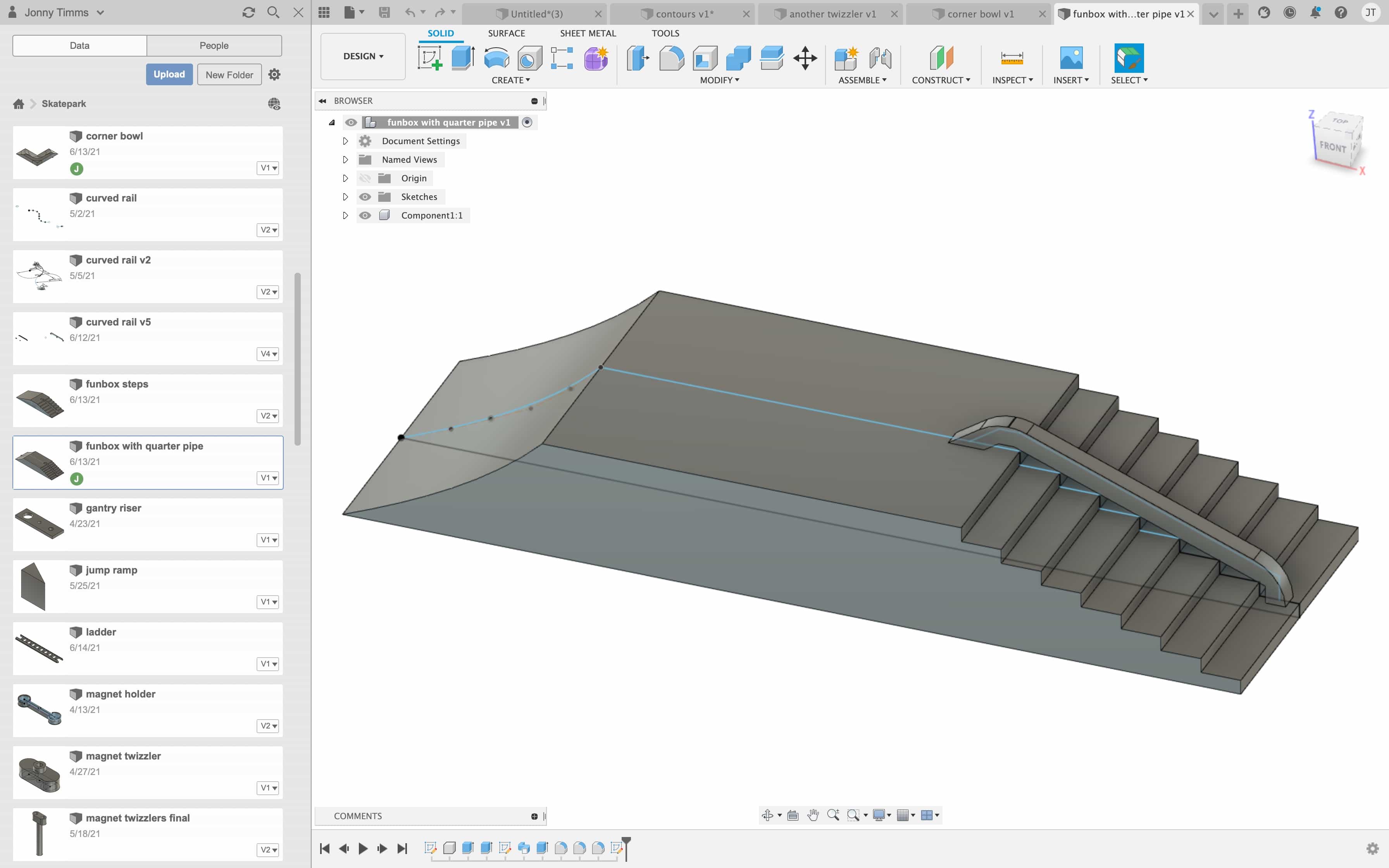
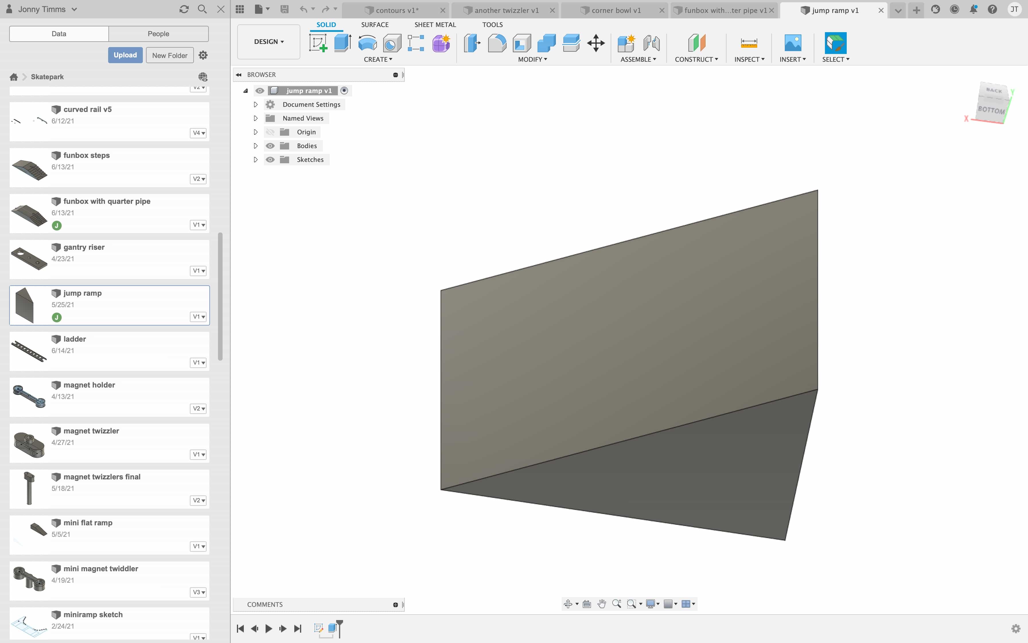
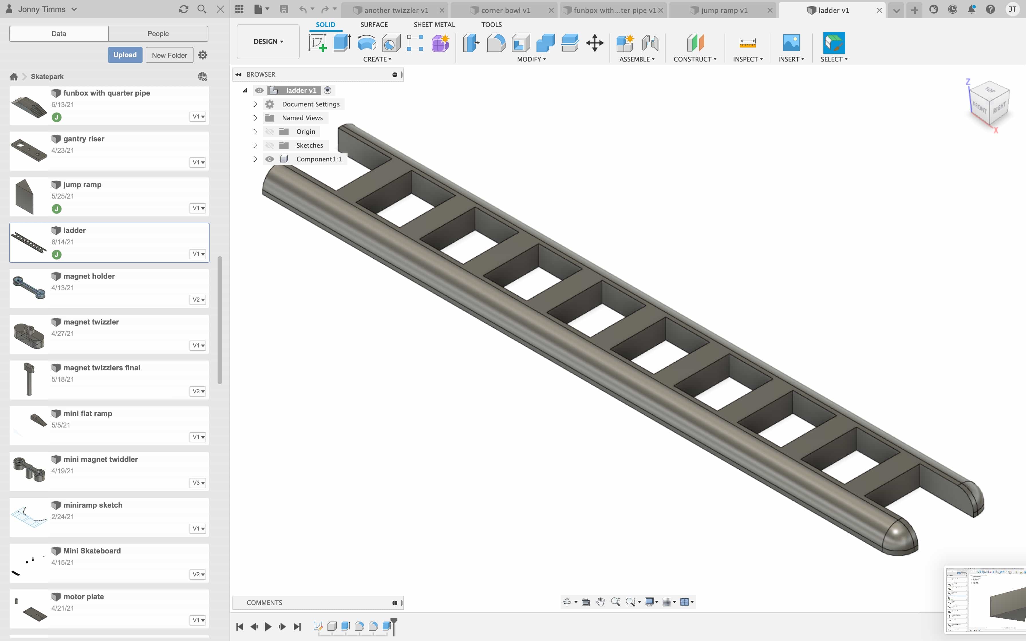
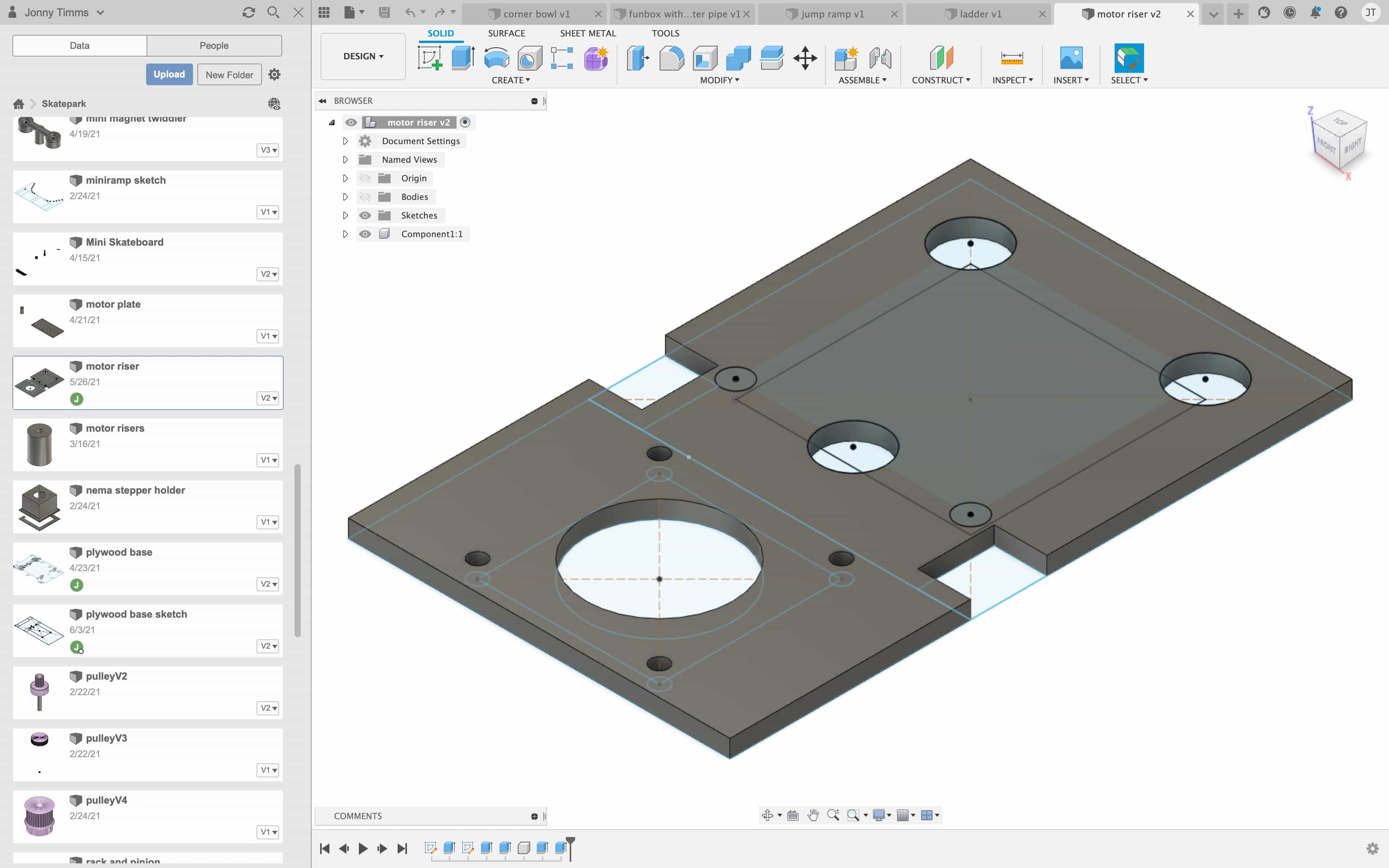
Additive fabrication process
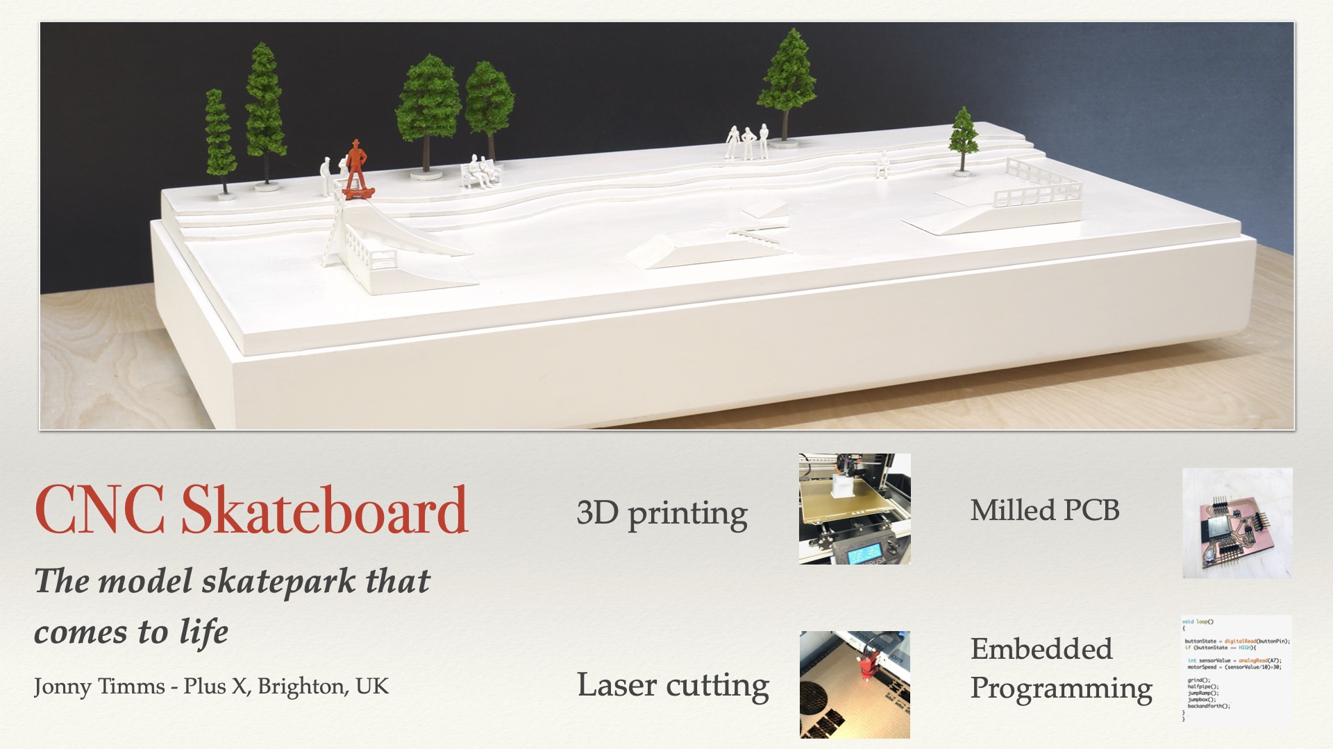
I 3D printed all of the obstacles in the skatepark. You can see them here on display in the final build:
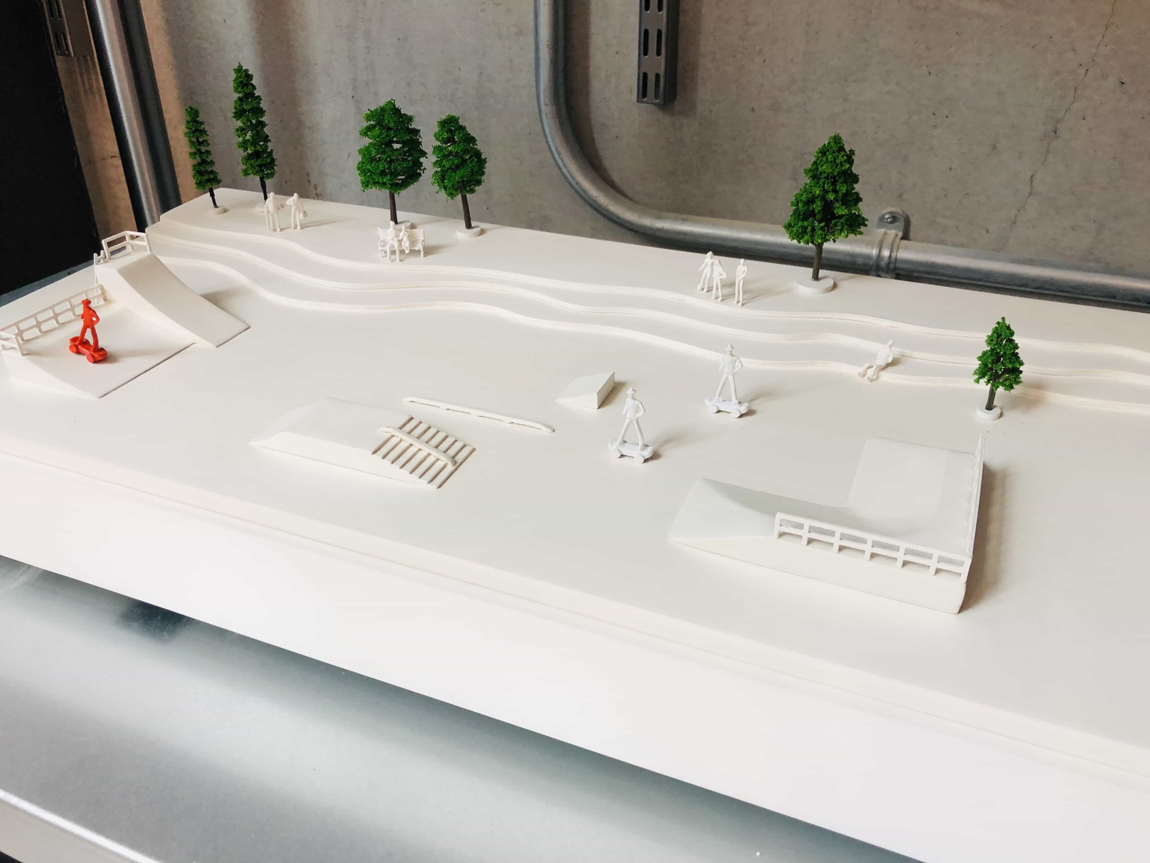
Subtractive fabrication processes
The main base is made from plywood and cut on the laser cutter. There are holes to mount the aluminium rails and the position of these holes is very important. Correct position ensures the rails are straight and parallel. If the hole was 1mm away from correct position, it would add too much pressure to the motor and will create a very noisy system. That is why I decided this part should be made on the laser cutter, to ensure precision of the hole location. This was made using 6mm plywood:
Now you can see the contours that I added to the model. These were made on the laser cutter using 4mm plywood:
Electronics design and production
I designed my board in EasyEda and using the ESP32 chip:
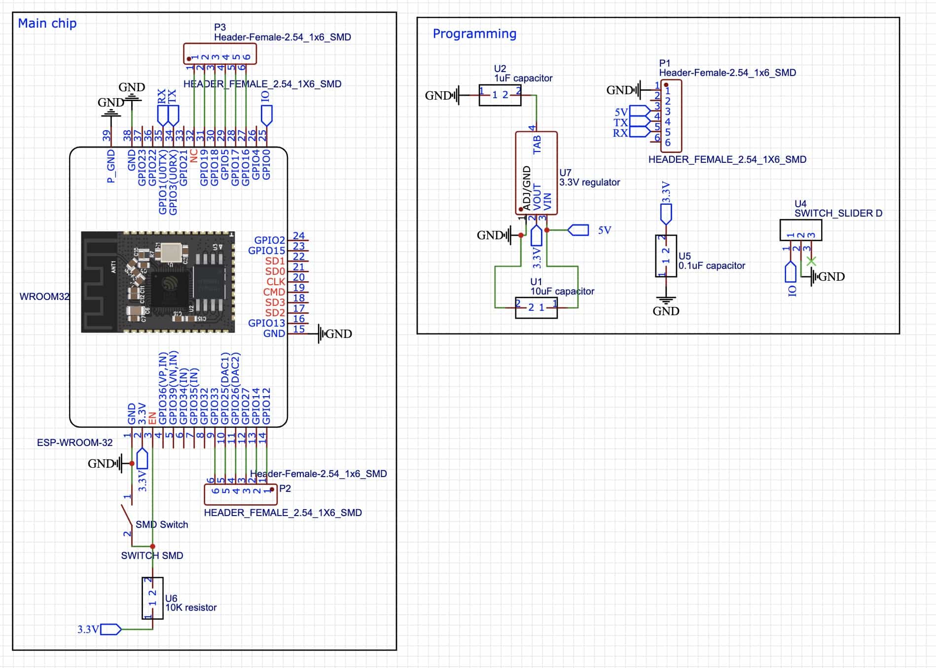
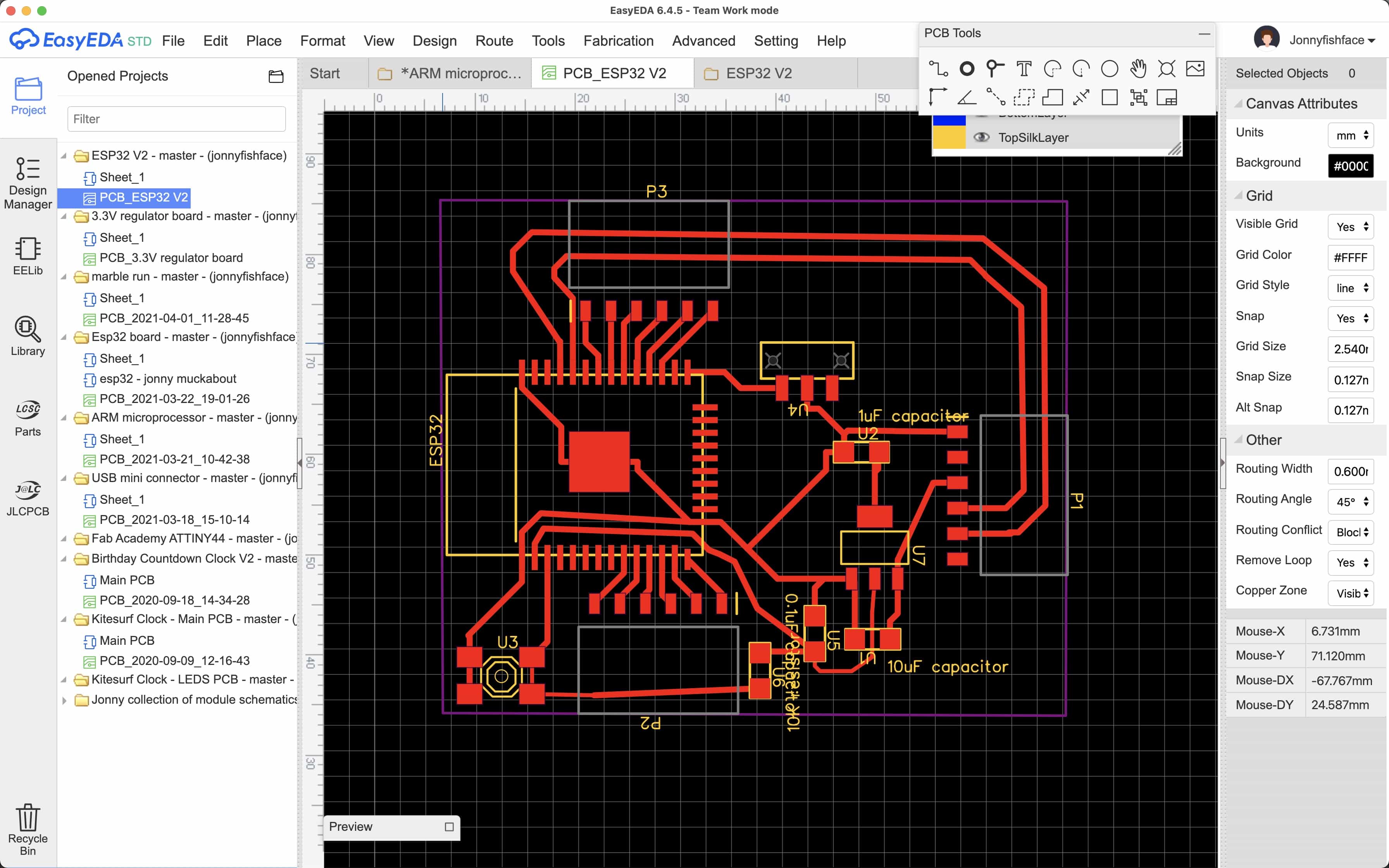
For more information on my electronics design and production, please check my week 6 assignment:
System integration and packaging
The casing for my final project included the following features:
- 6mm plywood frame - I considered using 18mm plywood which would have been stronger but I did not want the increased size. It would make my project 12mm taller, 12mm deeper and 12mm wider. I decided to use 6mm plywood that I would sand, prime and paint in white.
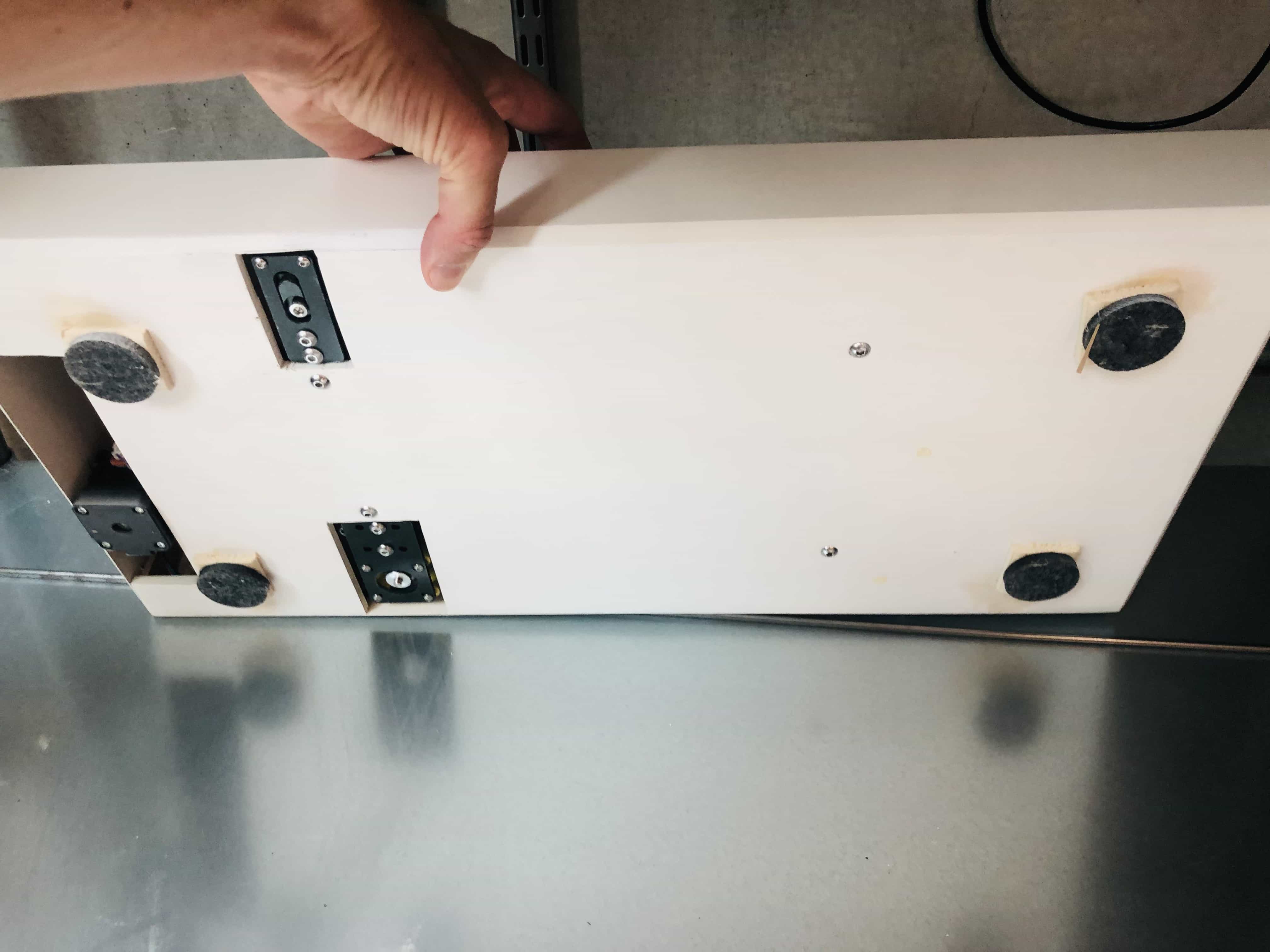
- 6mm felt feet x 4. These feet had 2 purposes. Firstly, to raise the model off the ground by 5mm which would create a more striking appearance. Secondly, I hoped they would help reduce the noise and vibration from the model.
- 6mm Chamfer on the bottom edge. I used the router tool to create a 45 degree chamfer around the lower edge of the main casing.
- All parts were treated with wood filler and then sanded, to create a smooth surface. Then everything was primed and painted with the same paint, to create a clean and consistent aesthetic.
Wiring
The wiring was difficult for this project. The position of the main wire connected to the rotating magnets was difficult to set up. I tried many different locations but the wire was getting caught on the moving parts. I tried using a wire carrier like you have in a 3d printer. Unfortunately there was not enough space, it would make the project more than twice the height. In the end I found a location in the center horizontally, but raised vertically by about 35mm. This location worked well, but it was necessary to attach the wires to the back of the motor mount plate. You can see in this video that the motors can move freely and wires are not caught on any moving parts:
The ESP32 board was secured to the base using double sided foam tape. The motor shield were screwed to the base using screws in the 4 corner holes. I forgot to take photos and then I took everything because I plan to use a new custom board with mounts for the motor drivers, directly built into my board. I took these quick photos to show the location of these boards when they were installed. Actually it works fine like this because the moving parts do not come close to the boards, but it will look better in the future when I have just one board and without motor shield.
Code
Why not use GBRL and gcode?
It feels like I'm re-inventing the wheel a little. Gcode would provide all the functionality of movement that I require. The issue is that I'm also using a 3rd stepper motor who's rotation needs to combine with the other 2 axis. Its not good enough to stop the X,Y axis from moving, move my 3rd stepper motor and then continue the movement of X,Y axis. The movement won't look like the natural motion of a skateboarder.
For example, I might want to create a for loop with 1000 iterations where the X axis moves by 1 step, the Y axis moves by 2 steps and my 3rd stepper motor rotates 1 step on every 4th iteration through the loops. My understanding is that this would not be easy to do with gcode. Although I'm sure there would be a way, it feels like it may be less work to just create the functions myself. Its also fun and good practice to use the maths required for these functions.
Why not use Arduino Libraries
I played around with some custom libraries which allow you to use acceleration and 2 axis movement, but they all have some limitations for my project. The acceleration libraries only allow you to accelerate one motor and although you could apply the library to both X and Y axis, it won't work in the way I require. The acceleration required for each motor is dependent upon the rate of the other. This won't allow me to create a natural movement for a skateboarder.
Straight vs Circular patterns
It took me a while to get my head around this, but when the magnet is moving, it is always moving either in a straight line or along part of a circular path where the circle has a radius and center point. If it looks like you're going in a gentle arc shape, this is just a circle with a large radius where the center point is a long way away. If the toolpath looks like a messy, wiggly line - it is actually just a series of small paths where each individual bit is either a straight line or part of a circle.
This means I can move the skateboard across any path using just 2 functions, one for moving in straight lines and one for moving around a circle. I'm planning to add functions for accelerate and another to execute a board slide. A board slide is where the skateboard rotates 90 degrees so it can slide along an obstacle.
My complete list of functions will be:
- Create a toolpath in a straight line
- Create a toolpath in a curved line
- Rotate the skateboard 90 degrees and back again to execute a board slide
A function for a straight path on a single axis
This function allows you to move in a straight line on either the X or Y axis. You can set the direction (Clockwise takes you right or up), the total distance in steps, the start speed and the finish speed.
void straight(char axis, char dir, int distance, int startSpeed, int finishSpeed){
int straightMotorSpeed = startSpeed;
int counter = 0;
for (int x = 0; x <distance; x++) {
counter = counter + 1;
moveMotor(axis, dir, 1, straightMotorSpeed);
straightMotorSpeed = round(float(startSpeed) + (float(finishSpeed - startSpeed)*(float(counter)/float(distance))));
}
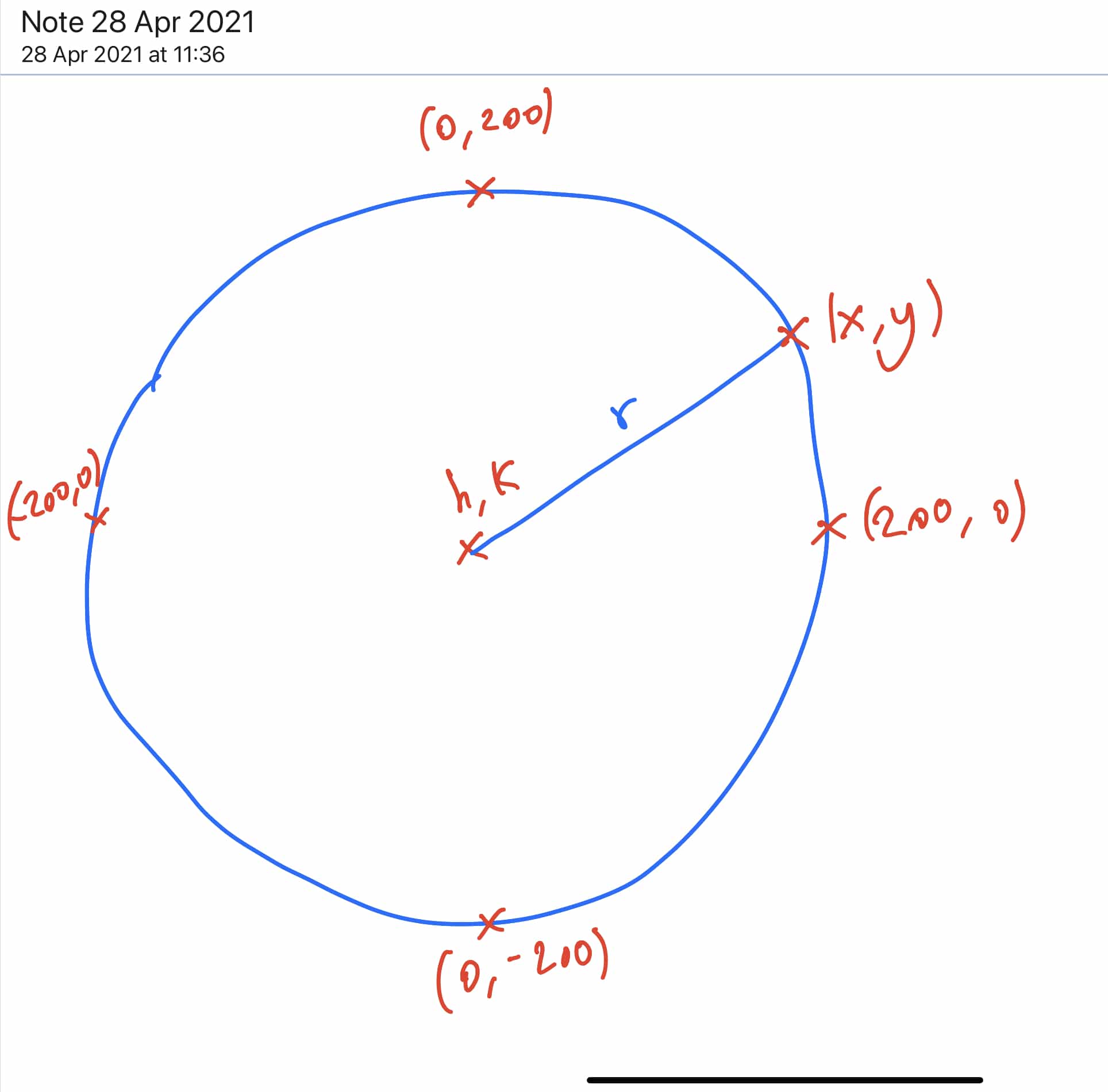
}Points on a circle
My function is based on the formula for points on a circle where radius = r and centrepoint = (h,k).
I've used a radius of 200 to illustrate this formula below:
A function for a circular toolpath
My function creates a circular toolpath and allows you to specify:
- The radius of the circle
- The X axis distance from current location to centre of circle
- The Y axis distance from current location to centre of circle
- The direction it should travel around the circle
- The percentage of the circle to travel
- The start speed
- The finish speed
void turn(int radius, int XdistanceToCentre, int YdistanceToCentre, char dir, float percentage, int startSpeed, int finishSpeed) {

    int oldXmagnet = -XdistanceToCentre;
    int oldYmagnet = -YdistanceToCentre;
    int oldXcircle = -XdistanceToCentre;
    float oldYcircle = -float(YdistanceToCentre);
    int newXcircle;
    float newYcircle;
    char Xdirection;
    char Ydirection;
    int circleMotorSpeed;
    int Xcounter = 0;
    int Ycounter = 0;
    float Zcounter = 0.0;
    float Zfigure = radius/400.0;
    int mycounter = 0;

    for (int x = 0; x <((float)radius*4.0*percentage); x++) {

      if (((oldYcircle>0)and(oldXcircle<0))or((oldXcircle==-radius)and(dir=='C'))or((oldYcircle==radius)and(dir=='A'))){   //if you're in the top left quarter of circle
      if (dir=='C'){
        newXcircle = oldXcircle + 1.0;
      } else if (dir=='A'){
        newXcircle = oldXcircle - 1.0;
      }
      newYcircle = sqrt(sq(float(radius)) - sq(float(newXcircle)));
    } else if (((oldYcircle>0)and(oldXcircle>0))or((oldXcircle==radius)and(dir=='A'))or((oldYcircle==radius)and(dir=='C'))){  //if you're in the top right quarter of circle
      if (dir=='C'){
        newXcircle = oldXcircle + 1;
      } else if (dir=='A'){
        newXcircle = oldXcircle - 1;
      }
      newYcircle = sqrt(sq(float(radius)) - sq(float(newXcircle)));
    } else if (((oldYcircle<0)and(oldXcircle<0))or((oldXcircle==-radius)and(dir=='A'))or((oldYcircle==-radius)and(dir=='C'))) {//if you're in the bottom left quarter of circle

      if (dir=='C'){
        newXcircle = oldXcircle - 1;
      } else if (dir=='A'){
        newXcircle = oldXcircle + 1;
      }
      newYcircle = -sqrt(sq(float(radius)) - sq(float(newXcircle)));
    } else if (((oldYcircle<0)and(oldXcircle>0))or((oldXcircle==radius)and(dir=='C'))or((oldYcircle==-radius)and(dir=='A'))) {  //if you're in the bottom right quarter of circle

      if (dir=='C'){
        newXcircle = oldXcircle - 1;
      } else if (dir=='A'){
        newXcircle = oldXcircle + 1;
      }
      newYcircle = -sqrt(sq(float(radius)) - sq(float(newXcircle)));
    }

    int Xchange = (newXcircle - oldXmagnet);
    int Ychange = (newYcircle - oldYmagnet);

    if (Xchange>0){
      Xdirection = 'C';
    } else {
      Xdirection = 'A';
    }
    if (Ychange>0){
      Ydirection = 'C';
    } else {
      Ydirection = 'A';
    }

    int Xsteps = abs(Xchange);
    int Ysteps = abs(Ychange);

// this will take out the natural acceleration and create a circular toolpath with constant speed
    if ((Xsteps <1) or (Ysteps <1)){
      circleMotorSpeed = regularMotorSpeed;
    } else if ((Xsteps ==1) and (Ysteps ==1)){
      circleMotorSpeed = regularMotorSpeed*0.71;
    } else {
      circleMotorSpeed = ((min(Xsteps,Ysteps)*(regularMotorSpeed*0.71))  + ((abs(Xsteps - Ysteps)*regularMotorSpeed))/(Xsteps + Ysteps));
    }
      float motorSpeedChange = float(finishMotorSpeed - startMotorSpeed)*percentageXstepsElapsed;


    float percentageXstepsElapsed = (float)Xcounter/((float)(radius*4.0*percentage));
    //float percentageYstepsElapsed = float(Ycounter/(float(radius)*4.0*percentage));
    float percentageZstepsElapsed = (float)Zcounter/((float)(1600*percentage));

    int circleMotorSpeed = startSpeed + round((finishSpeed-startSpeed)*percentageXstepsElapsed);

         if(percentageXstepsElapsed>percentageZstepsElapsed){
        moveMotor('Z', dir, 1, 5);
        Zcounter = Zcounter+1.0;
      }

    moveMotor('X', Xdirection, Xsteps, circleMotorSpeed);
    moveMotor('Y', Ydirection, Ysteps, circleMotorSpeed);
    Xcounter = Xcounter + Xsteps;
    Ycounter = Ycounter + Ysteps;

    if ((Zcounter*Zfigure)<Xcounter){
                moveMotor('Z', dir, 1, 5);
                Zcounter = Zcounter + 1;
      }

    oldXmagnet = oldXmagnet + (Xchange);
    oldYmagnet = oldYmagnet + (Ychange);
    oldXcircle = newXcircle;
    oldYcircle = newYcircle;
  }

}
Bill of Materials
What materials and components were used?
B.O.M.
| Material/Component: | Total spent: | Cost in final project: | Notes |
|---|---|---|---|
| PLA filament | £40 | £5 | Many failed prints while I tested designs for skatepark obstacles |
| Plywood in thicknesses of 1.5mm (the main surface), 4mm (the contours), 6mm (main casing) | £70 | £20 | I have lots of plywood remaining for future projects |
| Wood filler | £0 | £5 | Provided by lab but I have estimated cost |
| Primer | £20 | £20 | |
| Aerosol paint | £10 | £10 | |
| Varnish | £8 | £1 | |
| Glue (epoxy, super, PVA, hot) | £0 | £3 | Provided by lab but I have estimated cost |
| Felt | £0 | £2 | Provided by lab but I have estimated cost |
| Aluminium extrusion, size 2020 | £10 | £4 | |
| Aluminium gantry plate x 3 | £24 | £24 | |
| Nema 17 stepper motors 1.5A x 2 | £35 | £14 | Bought pack of 5 and used 2 |
| Nema 17 stepper motor 1A | £21 | £7 | Bought pack of 3 and used 1 |
| GT2 belt drive and pulley system | £15 | £15 | |
| Scale model people/tree set 1:75 | £10 | £2 | |
| Endstop switches x 2 | £7 | £2.80 | Bought pack of 5 and used 2 |
| Magnets in sizes 5x1mm, 5x2mm, 5x4mm | £10 | £1 | Tried many sizes and shapes but in final project, used just a small qty |
| Wires and JST connectors | £10 | £0.50 | Bought a complete set for future projects |
| ESP32 chip | £12 | £3 | Bought 4 and used 1 |
| Custom fab board | £0 | £3 | Provided by lab but I have estimated cost |
| Potentiometer | £0 | £0.50 | Donated by friend but I have estimated cost |
| Toggle switch x 2 | £5 | £1 | Used 2 from a pack of 10 |
| Stealth chop drivers x 3 | £20 | £15 | Used 3 from a pack of 4 |
| Untitled | |||
| TOTAL: | £327 | £158.80 |
Final project slide
Final project video
Files for download
Back to homepage: