Electronics design in KiCad
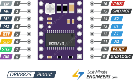
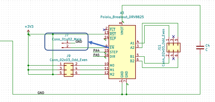
Since I did not have much experience in electronics design, I checked former Fab Academy students pages who have used the same microcontroller and also, my groupmates (Antti and Kenichi ) Output week as the references to get the ideas. I started with the drivers and the required components for each of them. Then, Juha-Pekka suggested me to check if EN pin in the driver should be connected or not. It can be left disconnected but I decided to connect it to the ground.
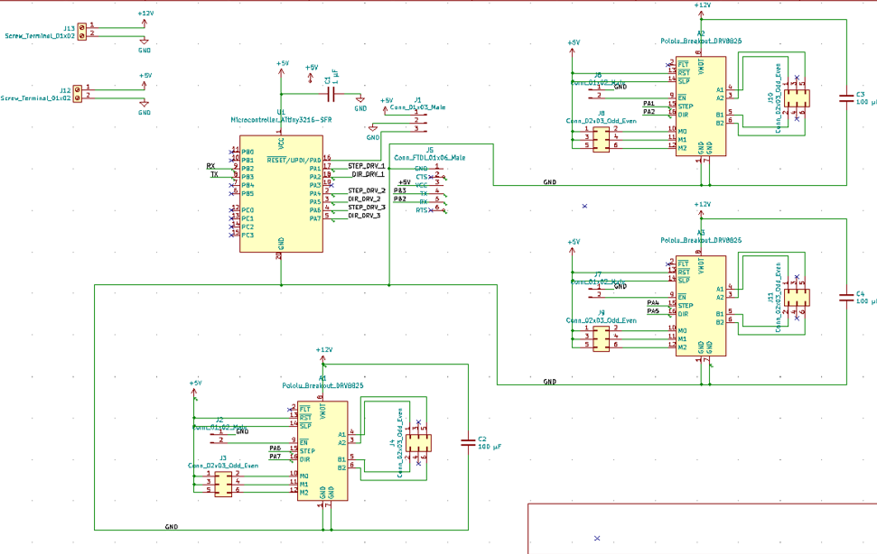
Since I was going to have three stepper motors, I designed three drivers in the board and completed it by assigning the proper voltage, capacitors and connectors for each part.
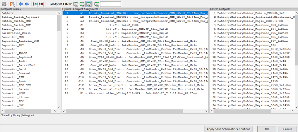
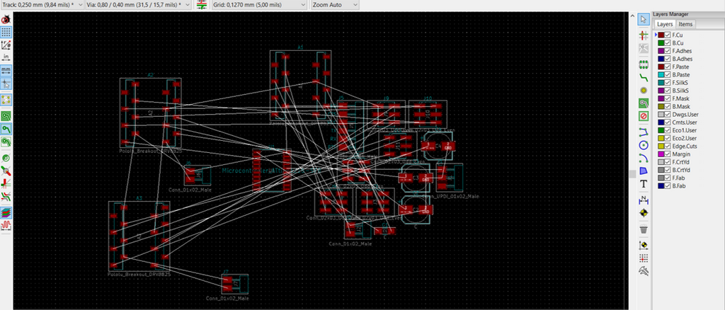
After discussing with Antti Mäntyniemi (our local instructor) and my groupmate, I found I can use another footprint for the drivers to get rid of making holes on the board.
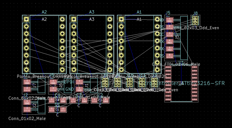
Figure 8. The first version of the footprint for the drivers
Then, I decided to customize the board and shape it as a triangle.
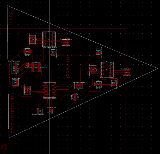
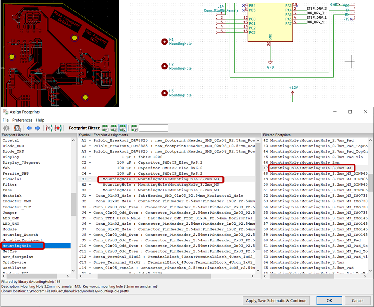
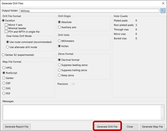
But with that design, I had several short circuits so I had to come up with other arrangement. I also needed to make some holes for mounting the board to the plate. So, I found the proper footprint for it from MountingHole footprint library and separately, generate drill files for it.
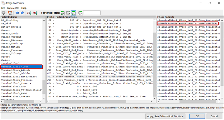
Also, for power supply, I used a terminal block which needed holes and for that, I found the correct footprint (Figure 13) with the help of Gleb who helped me a lot during my project.
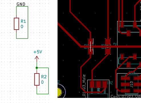
Since I had a quite big board and the traces had a high chance to cross, I learnt that for jumping over the traces, I can use 0 ohm resistor.
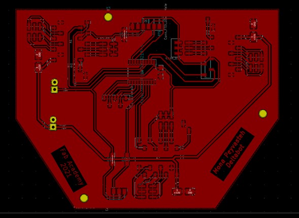
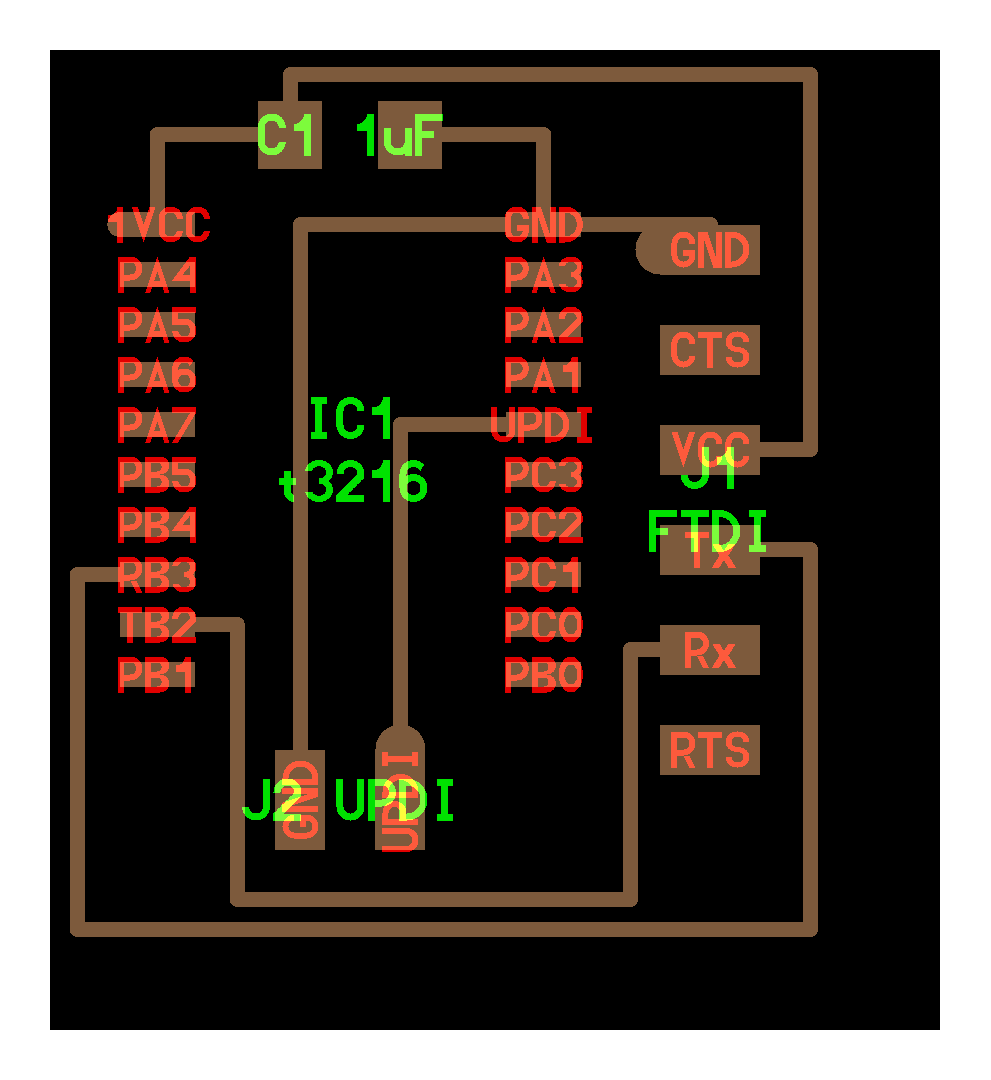
I also added a connector footprint for the free pins for furthur possible use of them. The final board layout looked like the following image:
Electronics production
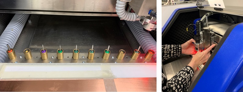
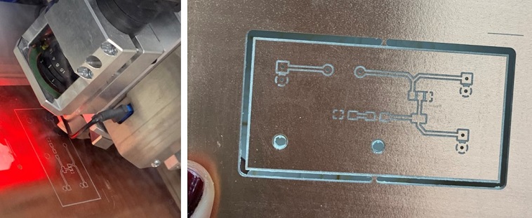
Milling with LPKF
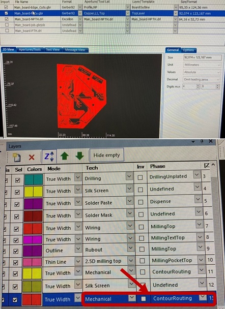
In LPKF CircuitPro PM software, I defined the drill files Tech as Mechanical and Phase as CounterRouting as my groupmate, Ken, did in his Output Devices week.
Some unexpected issues happened in the middle and one of the miling bits broke, drop and stuck in the machine. But with the help of Antti, it was solved.
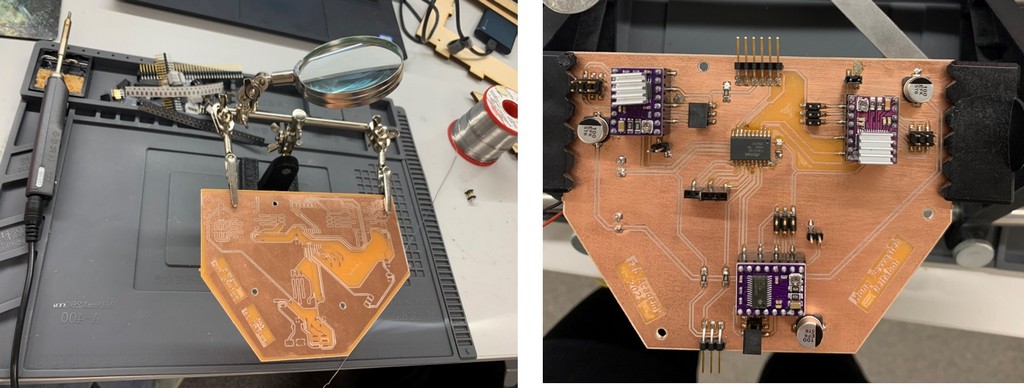
Finally, after spending several hours and several modifications in schematics and two times milling, I could succeed to make the pcb board and then, solder it.
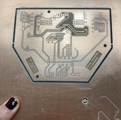
Figure 17. Finally, my beautiful board!*_*
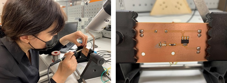
Soldering
Then, it was soldering time that is not much of my interest!:D The first try did not go well and the microcontorller burnt!:( So, I had to mill a new board and solder again. The list of electronics components I used to make my board was as the following:
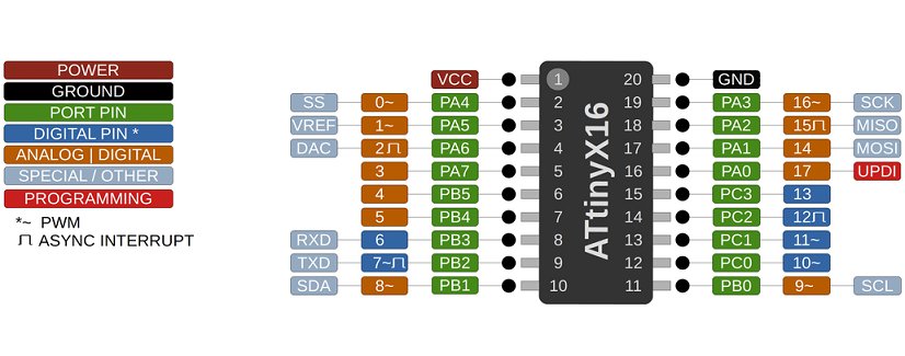
- ATtiny3216 microcontroller
- 3 x stepper motor drivers (DRV8825 )
- 1 x 1 uF capacitor
- 3 x 100 uF capacitors
- 1 x male header (1x3) SMD
- 3 x male header (1x2)
- 6 x female odd-even header (2x3)
- 1 x horizontal male header (1x3, UPDI)
- 1 x horizontal male header (1x6, FTDI)
- 2 x screw terminal block connector
- 3 x 0 ohm resistor
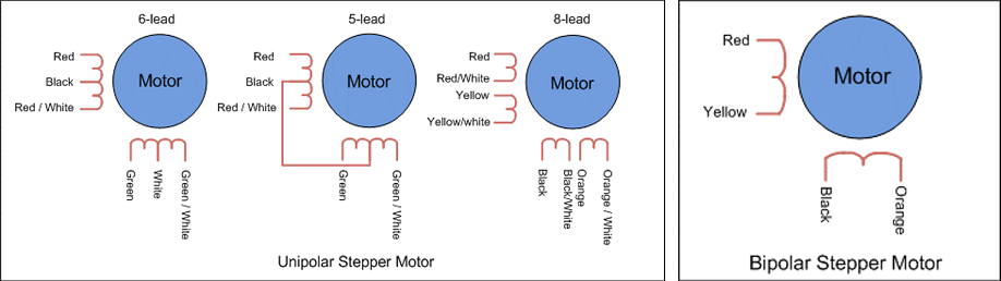
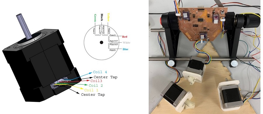
After finishing the board, it was the time to test the motors function. I just needed to know "stepPin" and "dirPin" I had assigned for each driver in my schematics. But before that, I arranged the motors wire with a connector according to NEMA17 pinout.
Here, Gleb suggested to add a button to power switch for the robot, so I had to quickly desing and mill another board.
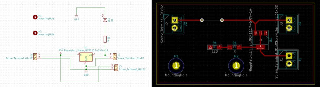
Again, I used LPKF machine to mill the board.
And then, soldered the components.
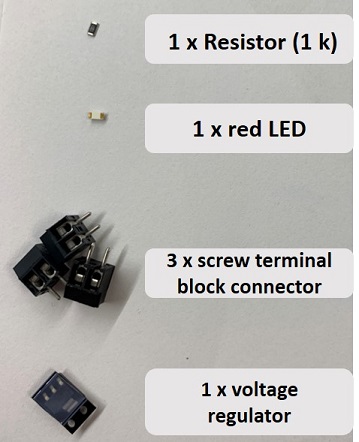
 The electronics components I used for this board were as the following:
Testing
Next, testing the button and LED:
And testing the button working with motors:
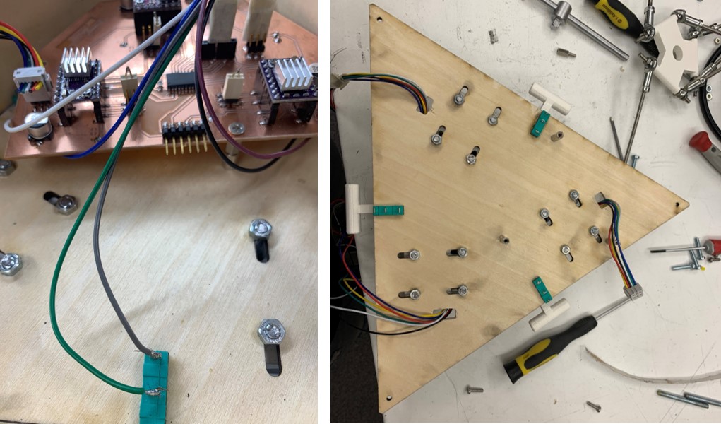
Then, testing with the mechanical body:I also added three limit switches to the upper plate to set the origo and connected to the microcontroller as the following picture. I will explain more about coding and finding origo in Embedded programming.
System integration
I made mounting holes on the boards to attach them to the upper plate. Also, I cut the motors wire to be shorter, rearrange them with the connector and tied them. Also, I had holes on the motor mount plate for the motors wiring going through them.
