Output Devices
Group Assignment
* Measure the power consumption of an output device
I measured power consumption by DC motor using DC power supply. I supplied the motor with 6 volts from
the supply and read the current absorbed from supply screen.
So the P=V*I=6*0.16=0.96 W.
Individual assignments
In this assignment I have to:
* Add an output device to a microcontroller board I've designed, and program it to do something
Output devices:
On the contrary from input devices, output devices are devices used to provide data and signals
from a microcontroller. This devices called actuators, which converts electrical signal to a physical
stimulus (such as heat, light or motion).
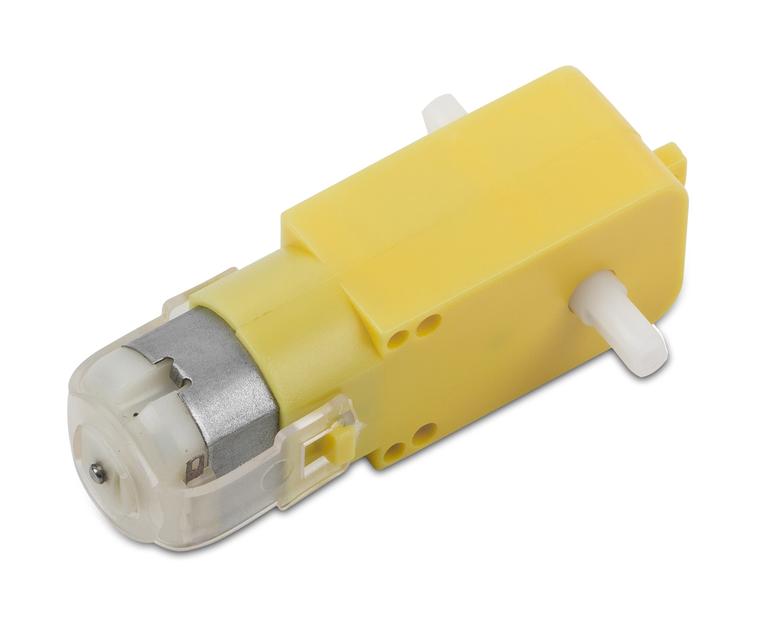
In this assignment I have test a DC motor which I will use in my final project.
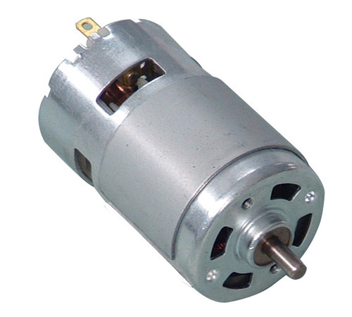
DC Motors:
Direct Current motors (DC motors ) are the most common type of motors. DC motors are electromechanical
devices which use the interaction of magnetic fields and conductors to convert the electrical energy
into rotary mechanical energy. They normally have two leads, one positive and one negative.
If you connect these two leads directly to a battery, the motor will rotate. If you switch the leads,
the motor will rotate in the opposite direction.
 There are many types of DC motors, some of them are geared and others are not.
Interfacing:
DC motors can not be connected directly to the microcontroller pins, because high absorbed current may damage the microcontroller. Another, I used 6 volts motor and the microcontroller drive only 5 volts.
So I need a driver circuit to supply and control the motor direction. after some search I found tutorial that using two relays as motor driver.
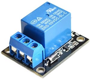
Relays:
A relay is an electrically operated switch. They commonly use an electromagnet (coil) to operate their internal
mechanical switching mechanism (contacts). Relays can be controlled through a low voltage signal and can be used
to control a high power circuit with a lower power circuit.
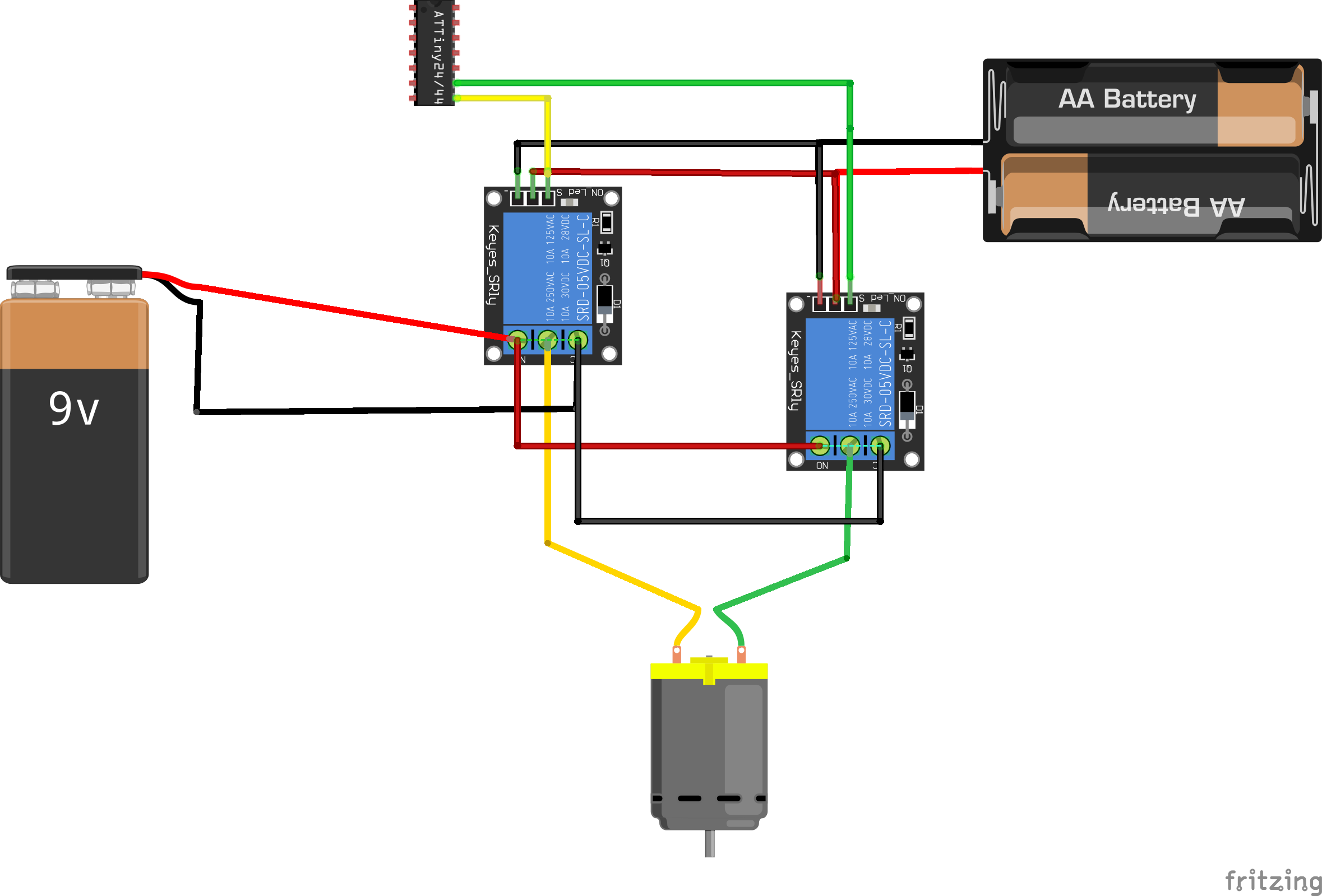
Connection:
To control the motor using relays I connect my board which I design in week7.
 The connection is:
 Programming:
I wrote a code using Arduino IDE to control the direction of the motor by using the relays, when one relay closed the motor rotates in a direction. And when the other relay closed the motor reverses.
The code:
Programming:
I wrote a code using Arduino IDE to control the direction of the motor by using the relays, when one relay closed the motor rotates in a direction. And when the other relay closed the motor reverses.
The code:
int Relay1 = 4;
int Relay2 = 5;
int LEDPin=0;
void setup() {
pinMode(Relay1,OUTPUT);
pinMode(Relay2,OUTPUT);
pinMode(LEDPin,OUTPUT);
digitalWrite(LEDPin,HIGH);
delay(500);
digitalWrite(LEDPin,LOW);
delay(500);
}
void loop() {
digitalWrite(Relay1,LOW);
digitalWrite(Relay2,LOW);
delay_ms(500);
digitalWrite(Relay1,HIGH);
digitalWrite(Relay2,LOW);
delay_ms(500);
digitalWrite(Relay1,LOW);
digitalWrite(Relay2,LOW);
delay_ms(500);
digitalWrite(Relay1,LOW);
digitalWrite(Relay2,HIGH);
delay_ms(500);
}
Now, I tested the motor as in the video: