Electronics Design
Group Assignment
* Use the test equipment in your lab to observe the operation of a microcontroller circuit board (in minimum, check operating voltage
on the board with multimeter or voltmeter and use oscilloscope to check noise of operating voltage and interpret a data signal)
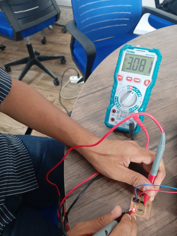
I used Digital Multimeter to measure the microcontroller operating voltage. It was about 5 volts.
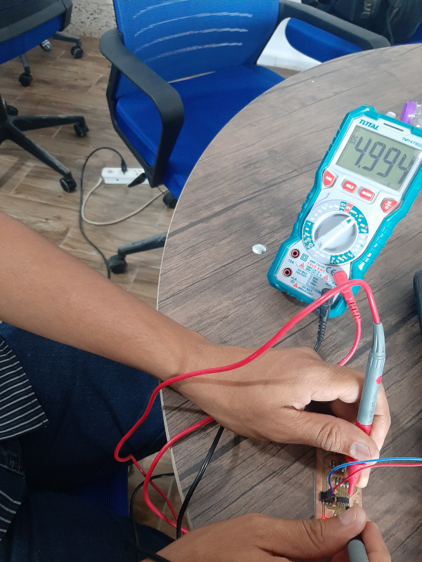 And the output voltage from a pin is more than 3 volts.
Individual assignments
In this assignment I have to:
* Redraw one of the echo hello-world boards or something equivalent, add (at least) a button and LED (with current-limiting resistor) or
equivalent input and output, check the design rules, make it, test it.
Board Design:
I have a good experience in Proteus design software and I used it in PCB design many times, but it is first time to test EAGLE. I think it will
be a good experience.
Fabcloud has a good tutorial introducing EAGLE. I read it before starting and it was very helpful.
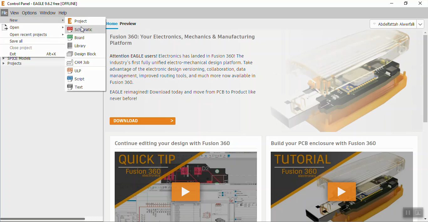
What is EAGLE?
EAGLE is an electronic design automation (EDA) software that lets printed circuit board (PCB) designers
seamlessly connect schematic diagrams, component placement, PCB routing, and comprehensive library content.
After downloading and installing EAGLE I download and add fab EAGLE library from this link. This library includes extra components needed
to design my PCB.
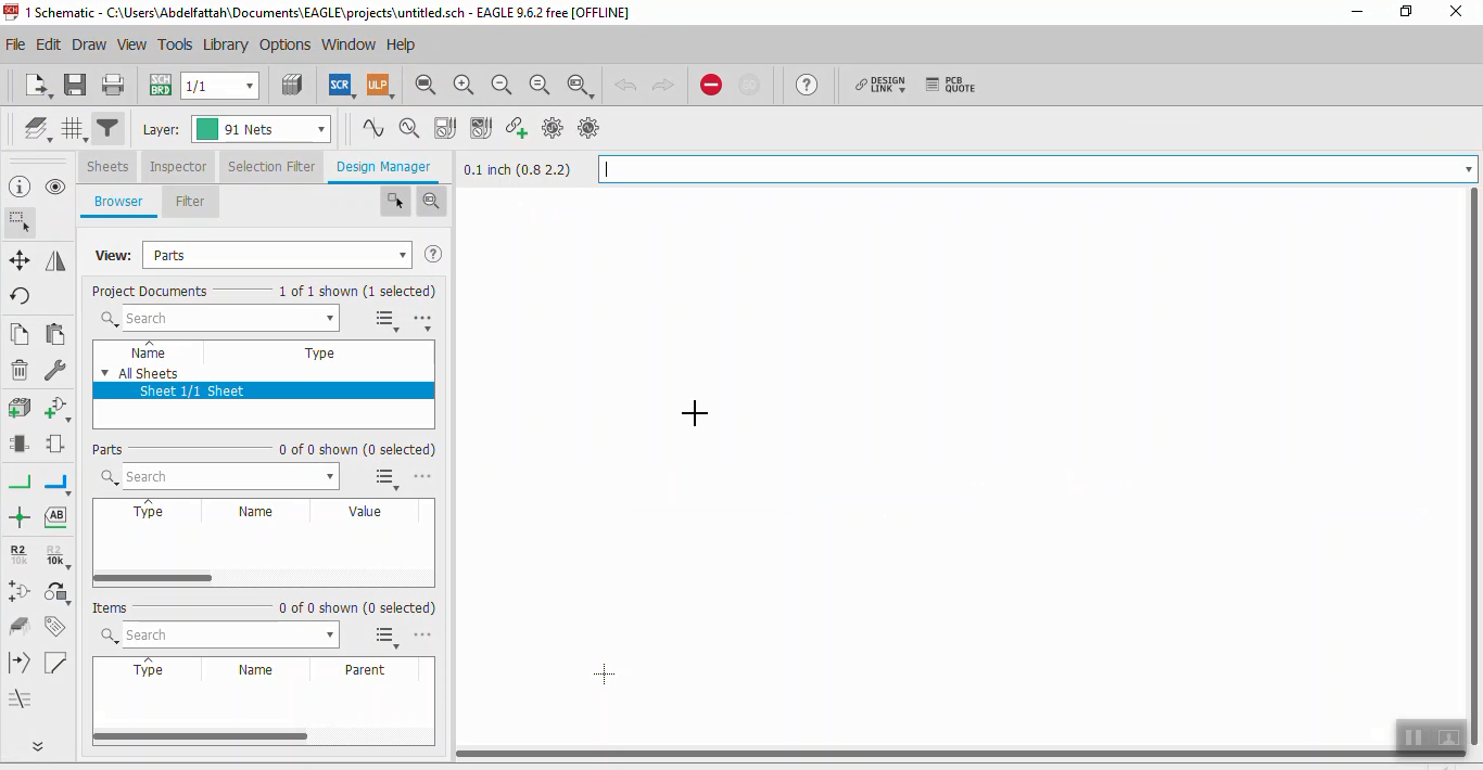
Schematic Design:
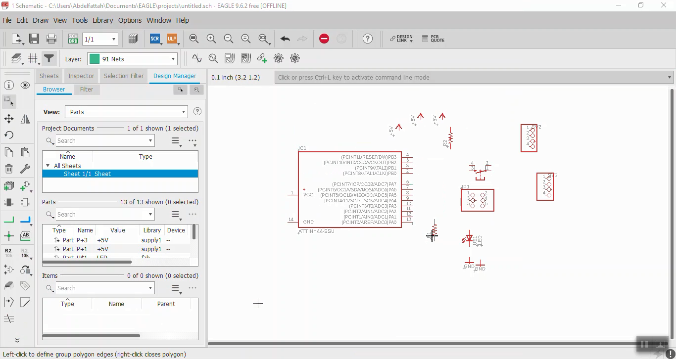
First step in PCB design is schematic, which is a simple two-dimensional circuit design showing the functionality and connectivity between
different components. To start a schimatic, from control panel File/new/schematic.
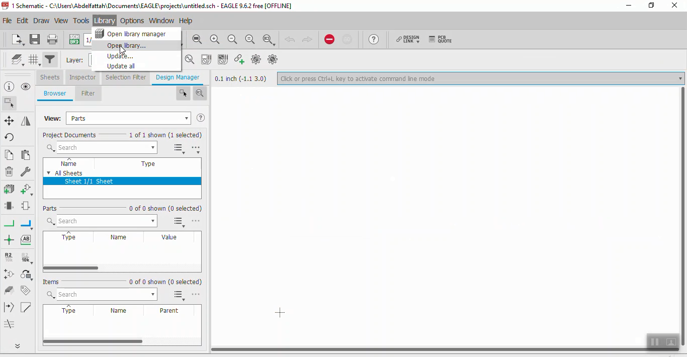
 To start adding the components, click on Library then open library. A new window will open. swlect your device then click add to schematic.
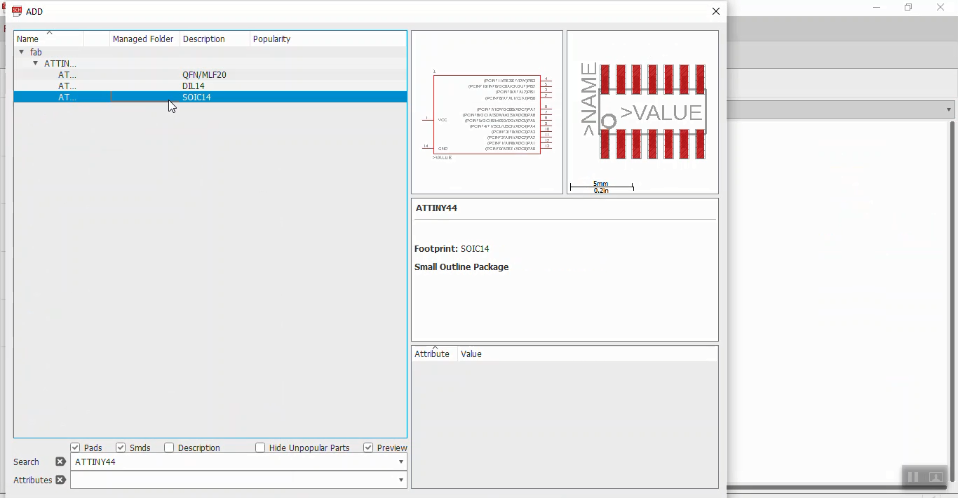
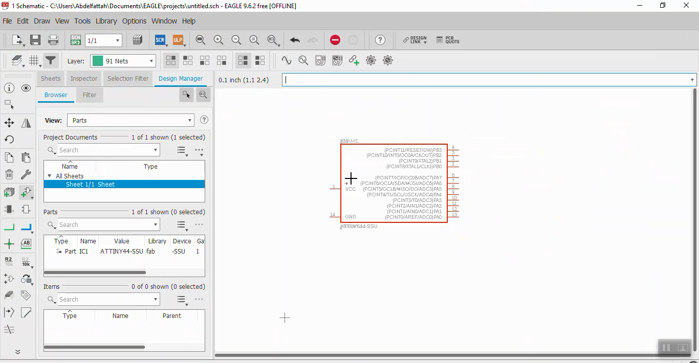
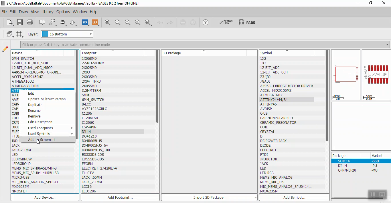 Select the right package and the device will appear in the schematic
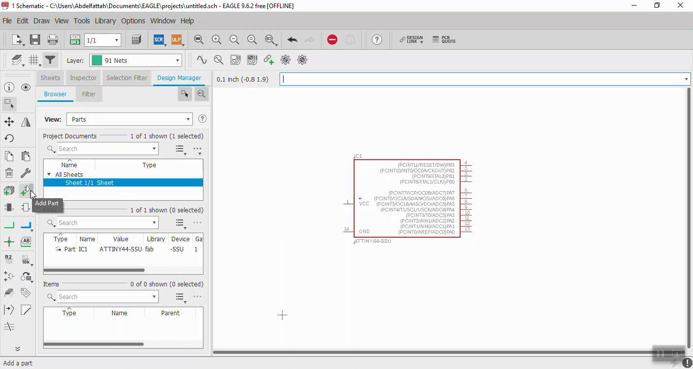
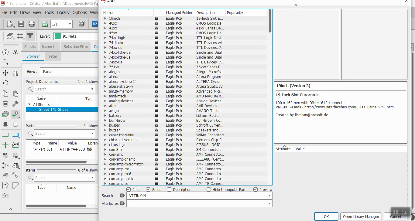
 To use EAGLE built in components use Add Part.
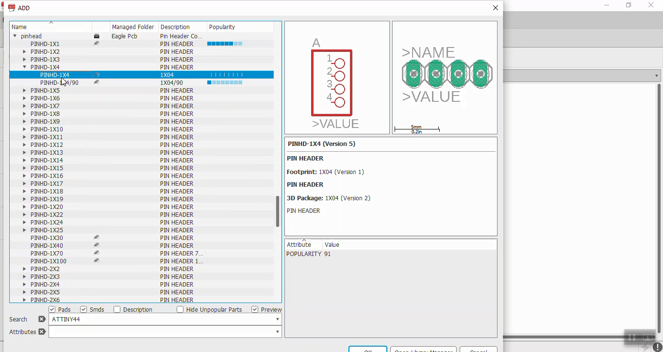
 Adding connectors ans ISP connector.
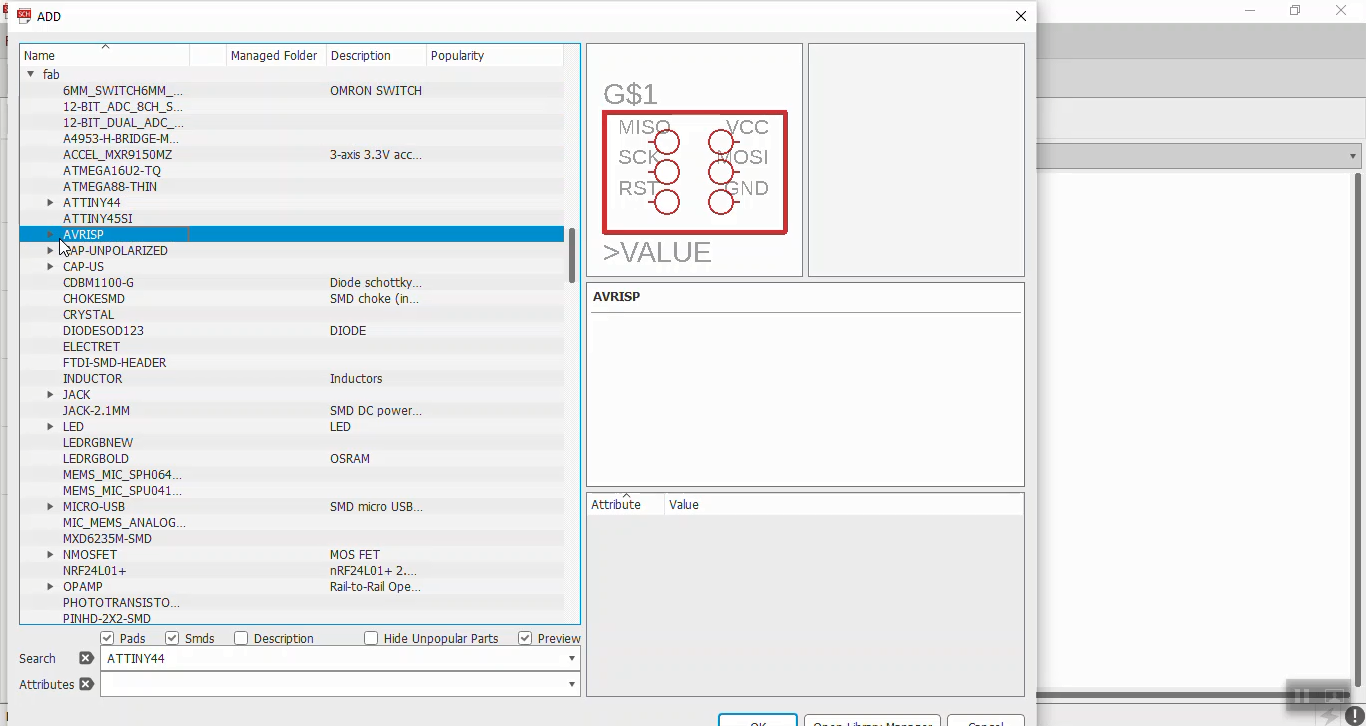 Add other components and connecting them.
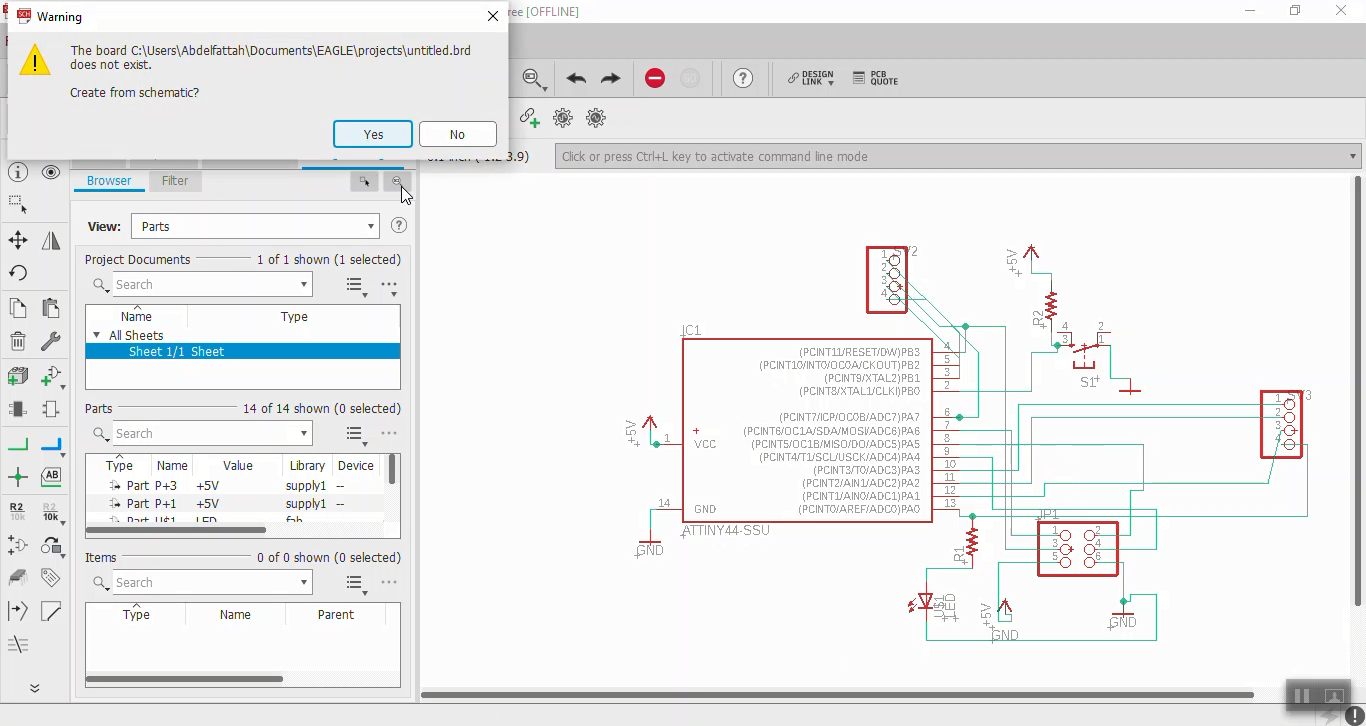
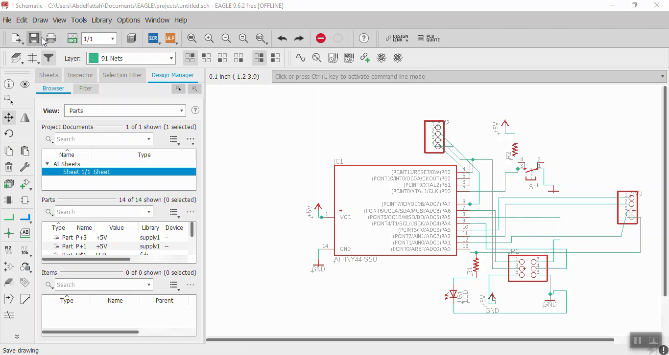 To start PCB design click on Generate or Switch to Board.
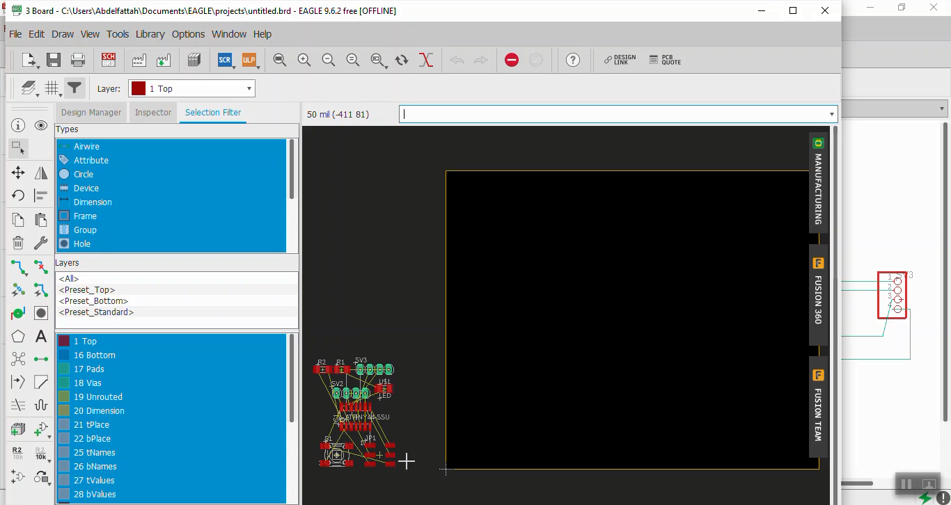
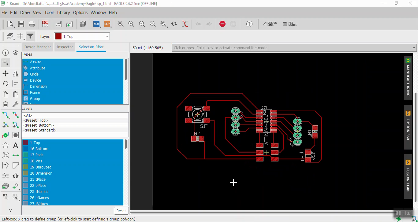
 All copmonents will appear in the left corner, move them to get your final circuit. Then trace the components.
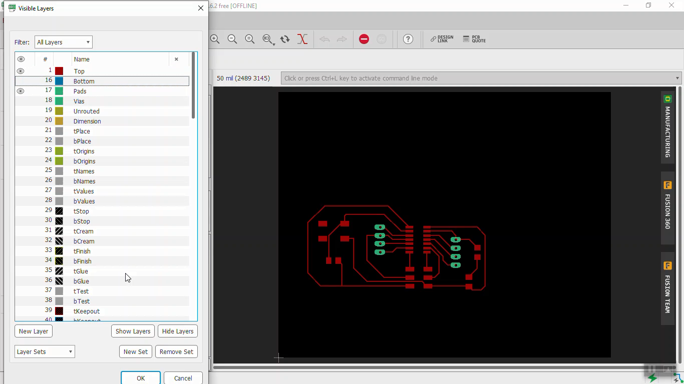
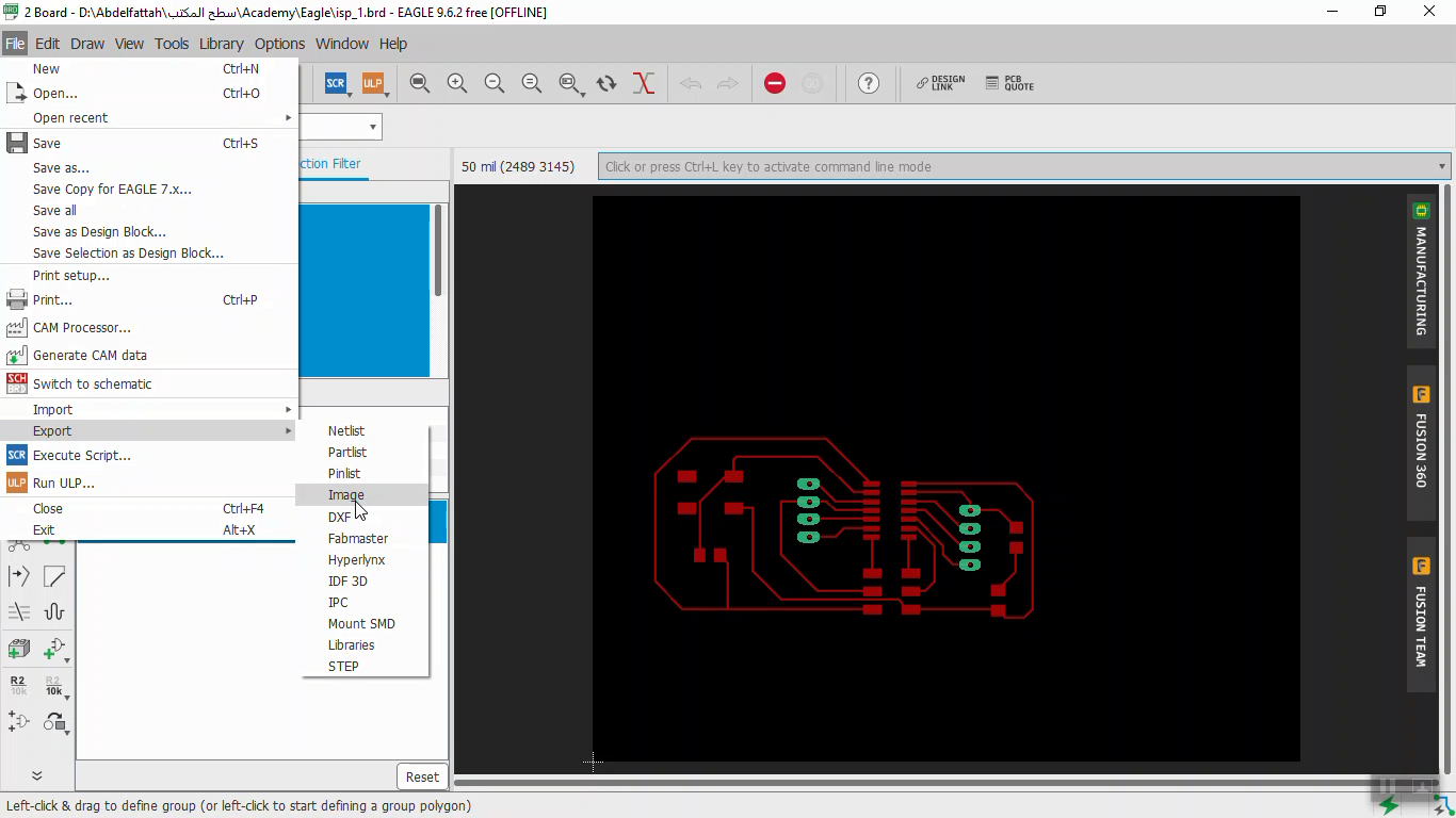
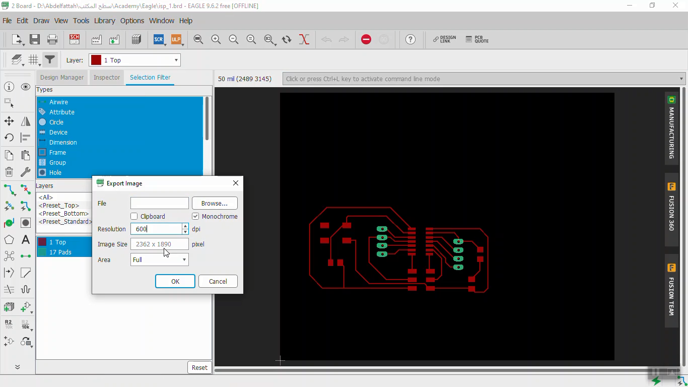
 To export the design as image we must:
1. From Layer settings hide all layers except Top and Pads Layers.
2. Select exporting Image from File/export/Image.
3. Change the resolution to 600 dpi, select monochrome and the file path then ok.
To export the design as image we must:
1. From Layer settings hide all layers except Top and Pads Layers.
2. Select exporting Image from File/export/Image.
3. Change the resolution to 600 dpi, select monochrome and the file path then ok.
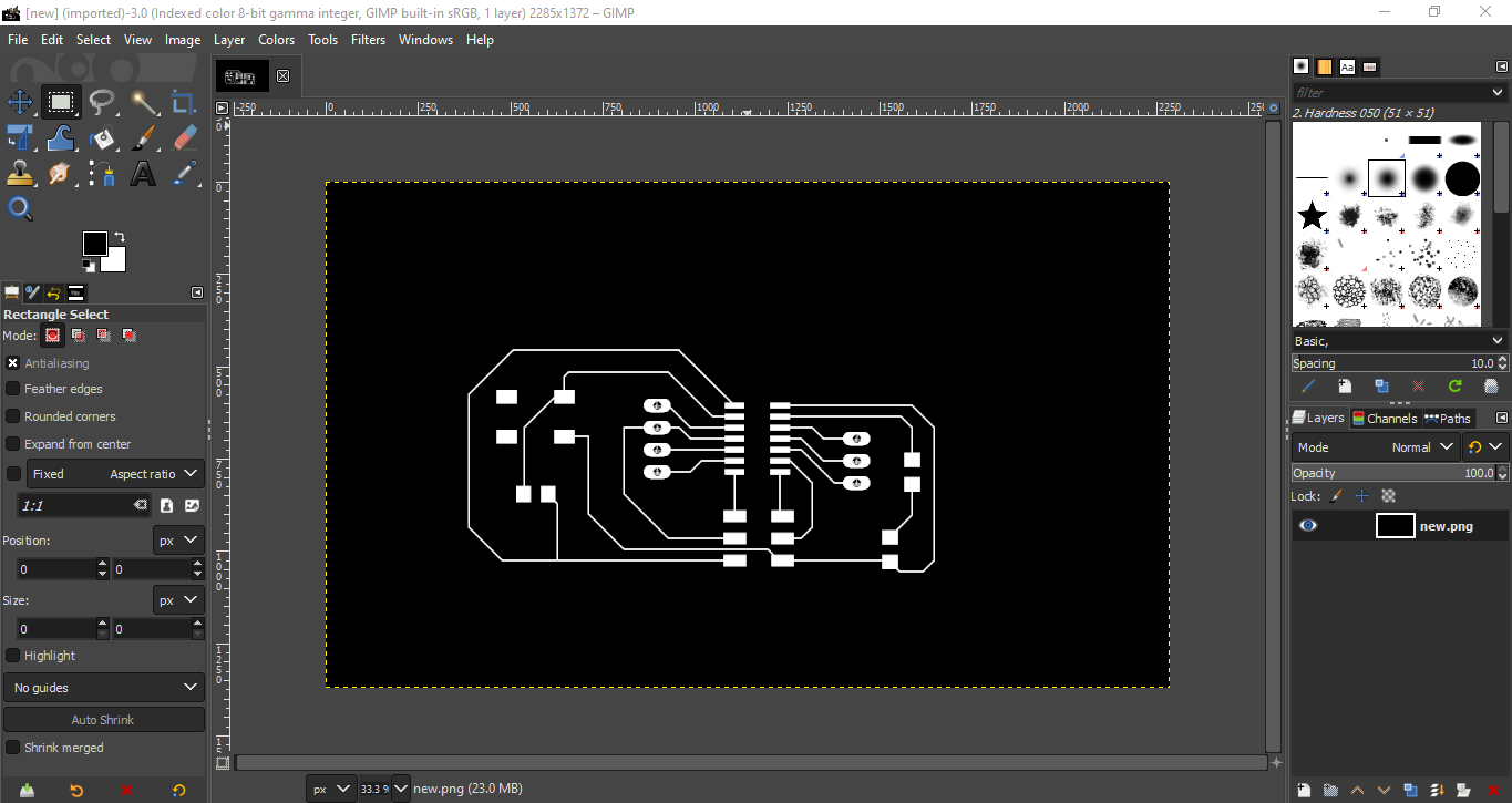
 Now, adding some editing to the picture using GIMP.
 PCB Production:
To calculate the G-Code of my PCB I used Fabmodules as next steps:
PCB Production:
To calculate the G-Code of my PCB I used Fabmodules as next steps:
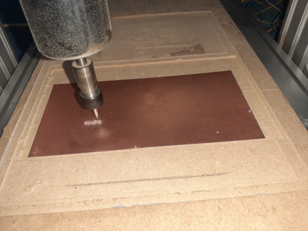
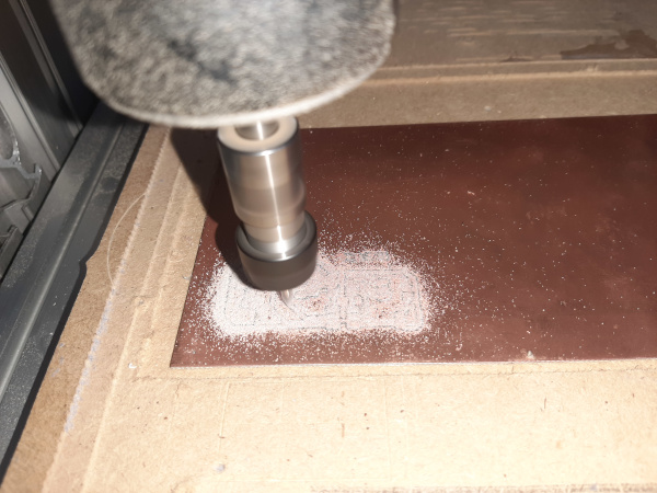
 After that using CNC machine for milling the circuit. First install the milling tool and adjust xyz positions.
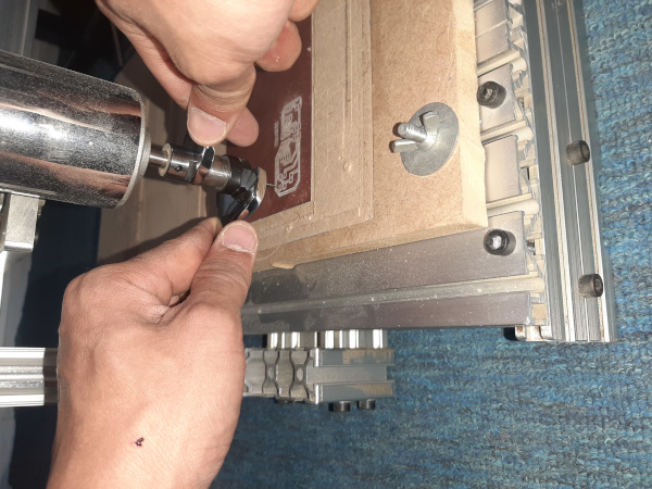
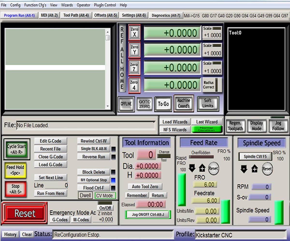
 My CNC machine is controlled by Mach3 software.
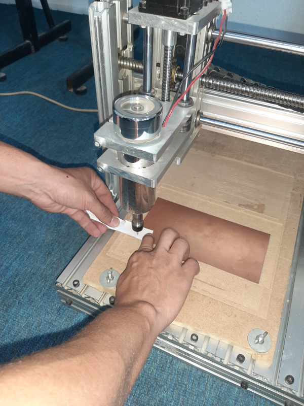
 Now, starting milling:
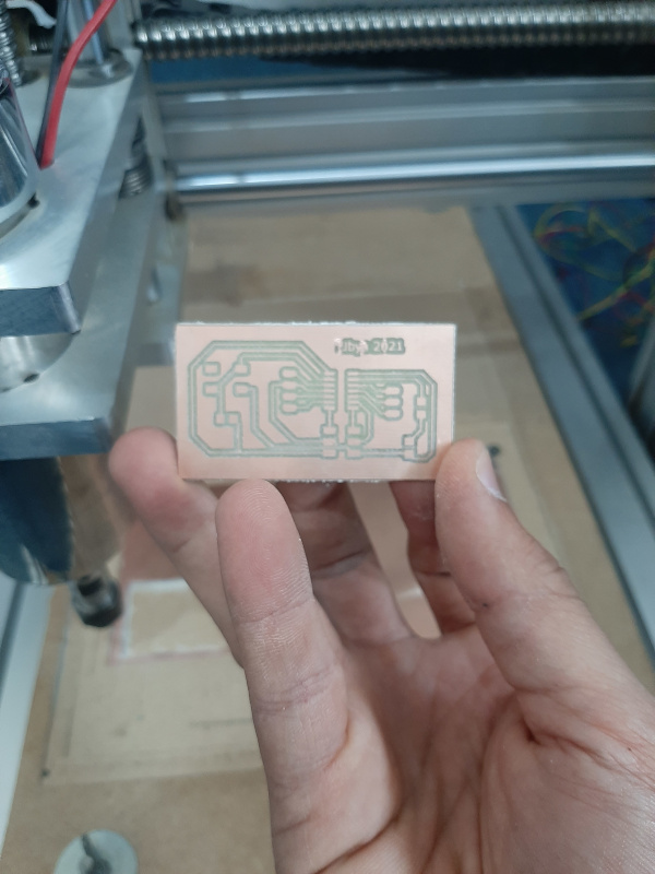
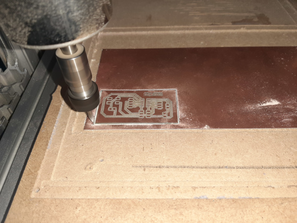 The PCB after milling:
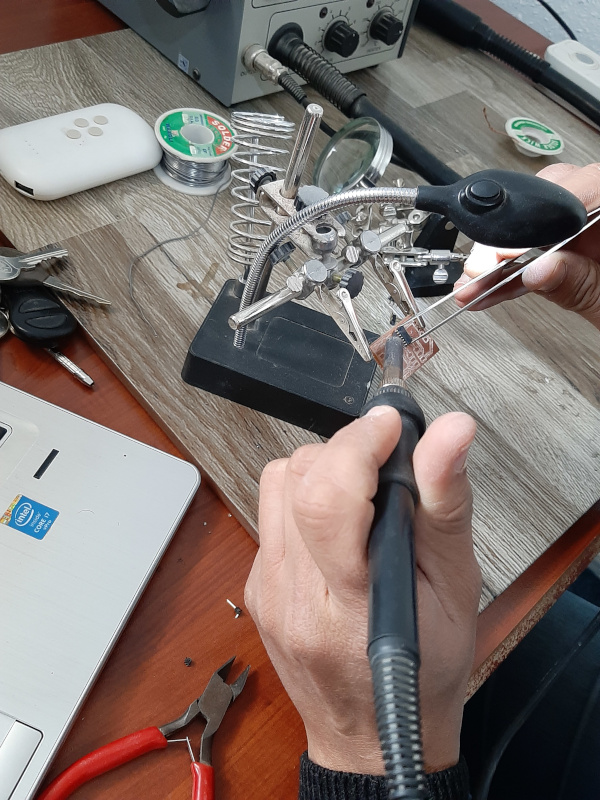
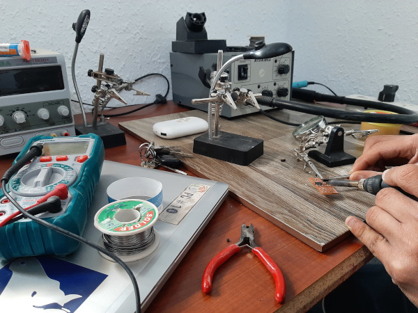
 To make sure that all traces are connected, I used Multimeter to test them.
After testing start soldering starting with the microcontroller.
To make sure that all traces are connected, I used Multimeter to test them.
After testing start soldering starting with the microcontroller.
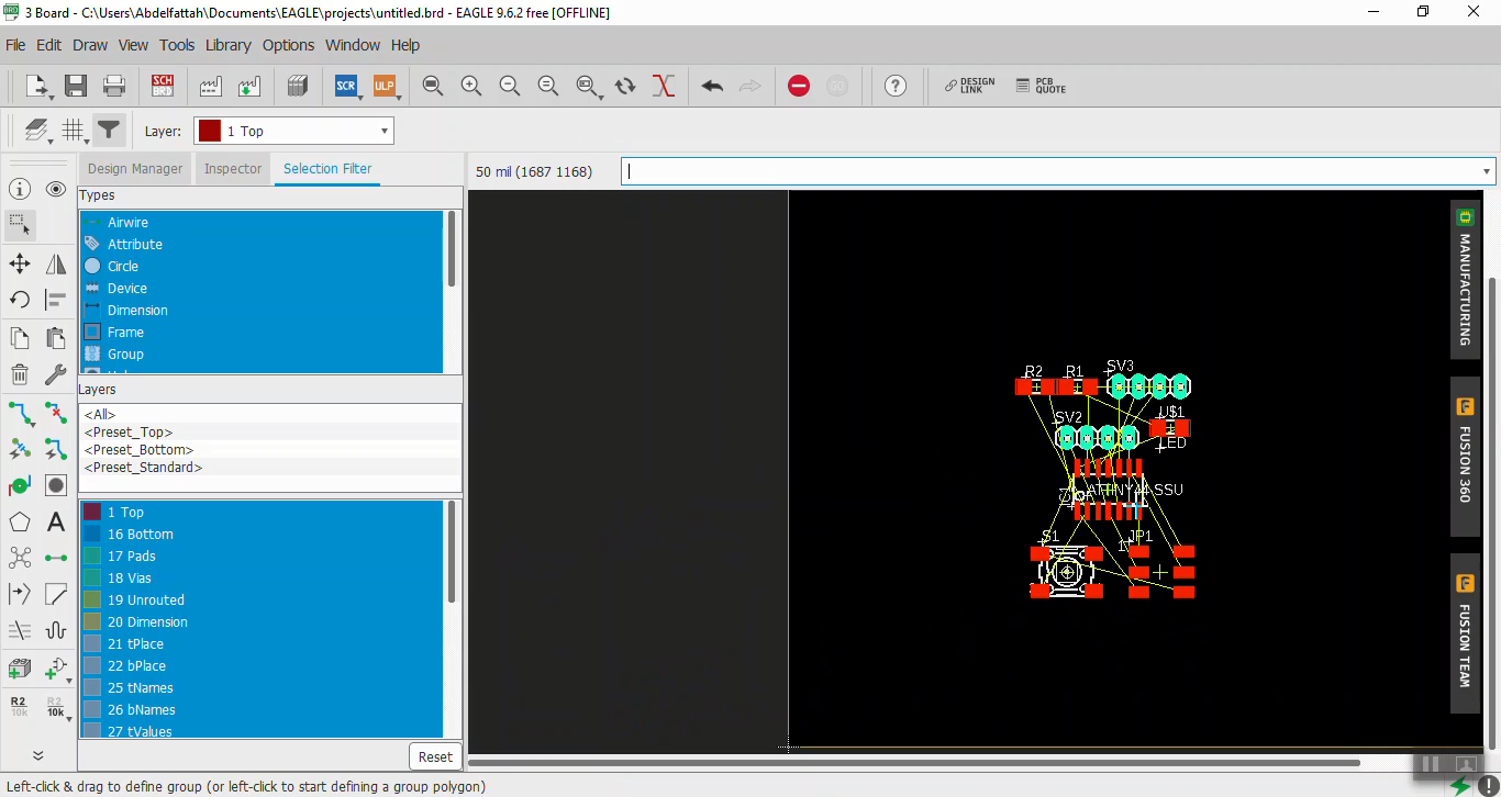
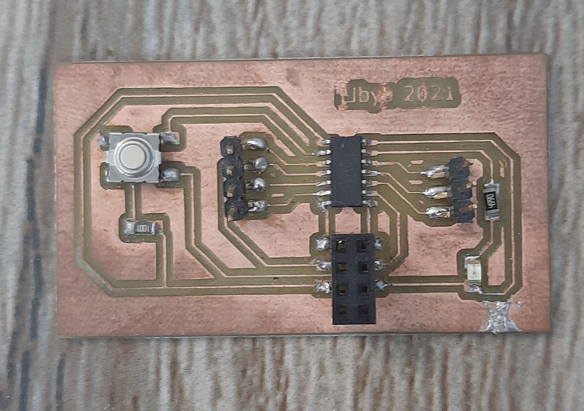
 The complete circuit is:
Programming and Testing
Now, I used same steps in week 9 to uplaod a simple button program to my board.
Download Files:
My Design files:
Arduino Code: