Networking and Communications
Welcome to a very weird week for me in FabAcademy! This was supposed to be the week where I could finally connect my OLED screen from the previous week to the RFID sensor.. I was really looking forward to work with this technology. Sadly, the destiny had other plans. Fellow FabAcademy student (and yes, by this time I can call her a friend) Lorena, tested Covid positive on Friday, so I could not go to the lab anymore. By the time I'm writing this, May the 5th, lecture day, I'm still locked down in my room, waiting for the results of my PCR test. The board, however, had to be milled weeks later
But the fact I was locked down does not mean I could not do anything. I could prepare the board that failed miserably in the input devices week. I wanted to create a HelloRFID board with a BUS connection, so I opened Eagle and cue the music
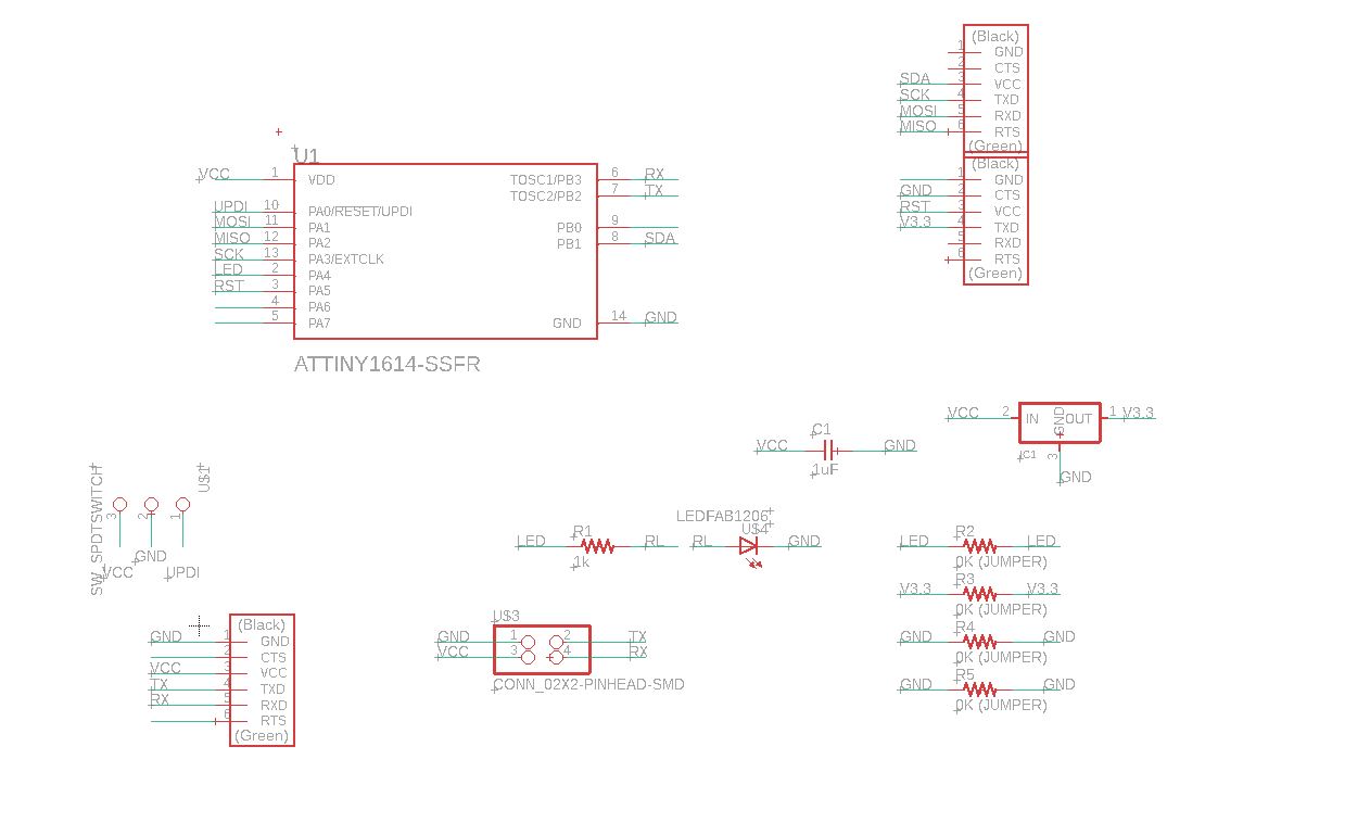
This board is based in Neil's example, but modified so it could be used with a BUS connector.
So even if it's a mess and it was going to need four jumpers, I was determined to create an RFID reader, once and for all
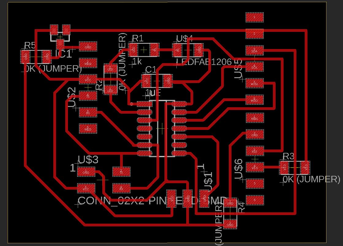
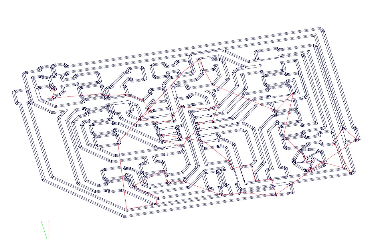
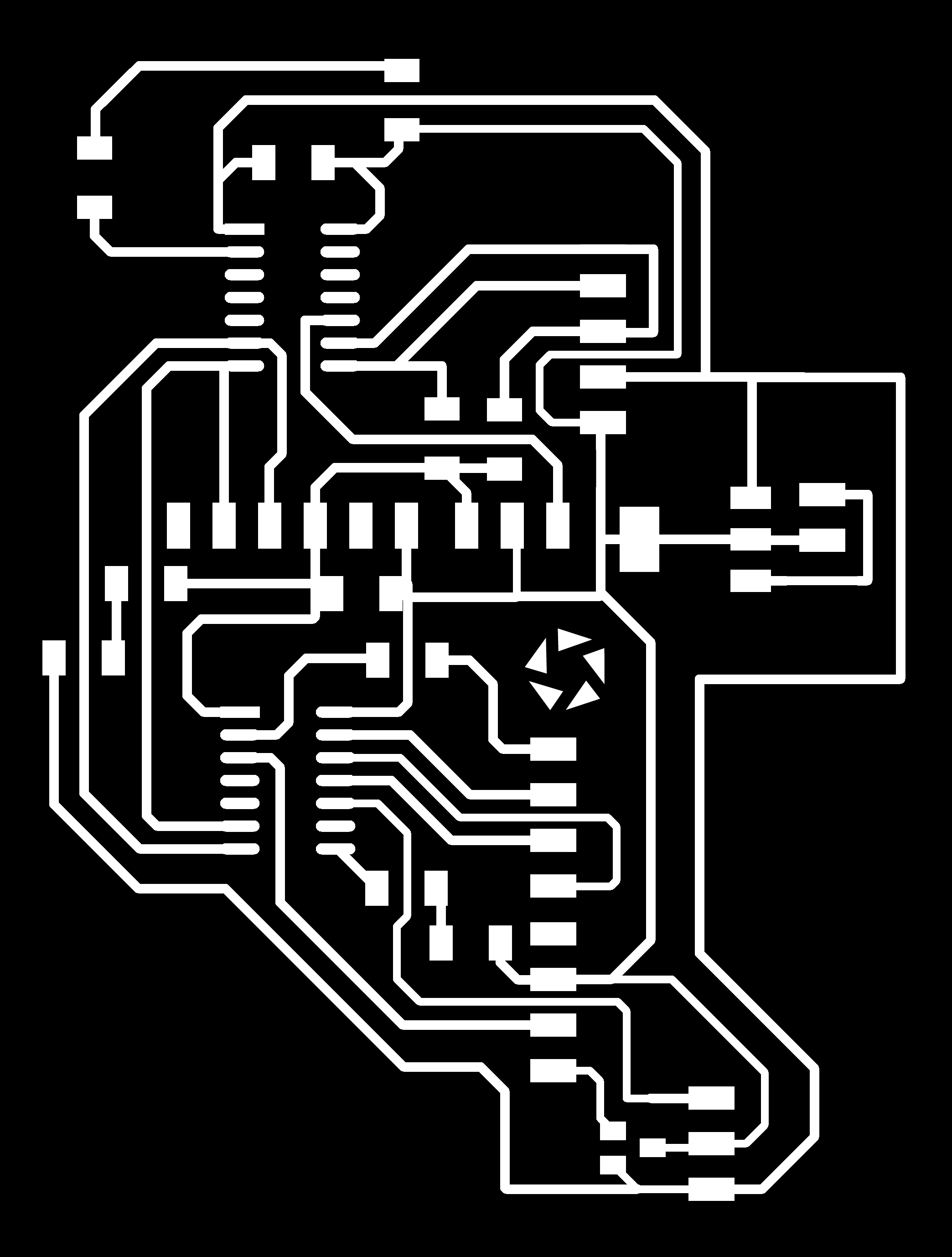
These are the traces:
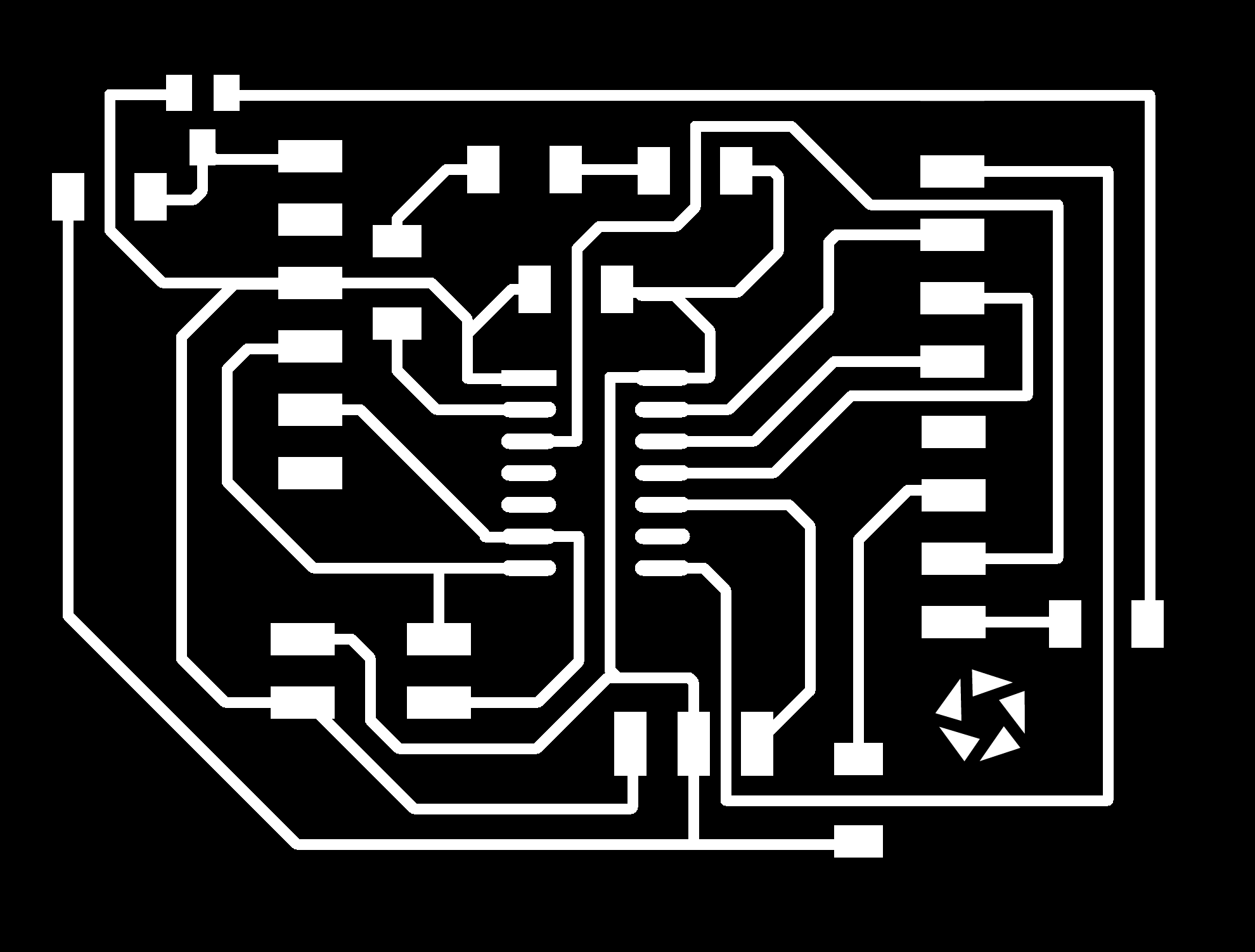
And this is the PNG file for the outlines:
I created the RML file using FabModules, as I've done during my whole FabAcademy journey, and got the file ready to be milled in my board
Sadly, though, even if I thought that by this time I was going to be able to go out, my PCR results are still not ready, and I'm locked in my room. I'll revisit this assignment in the following days.
You can get the Eagle board file HERE.
You can get the Eagle schematic file HERE.
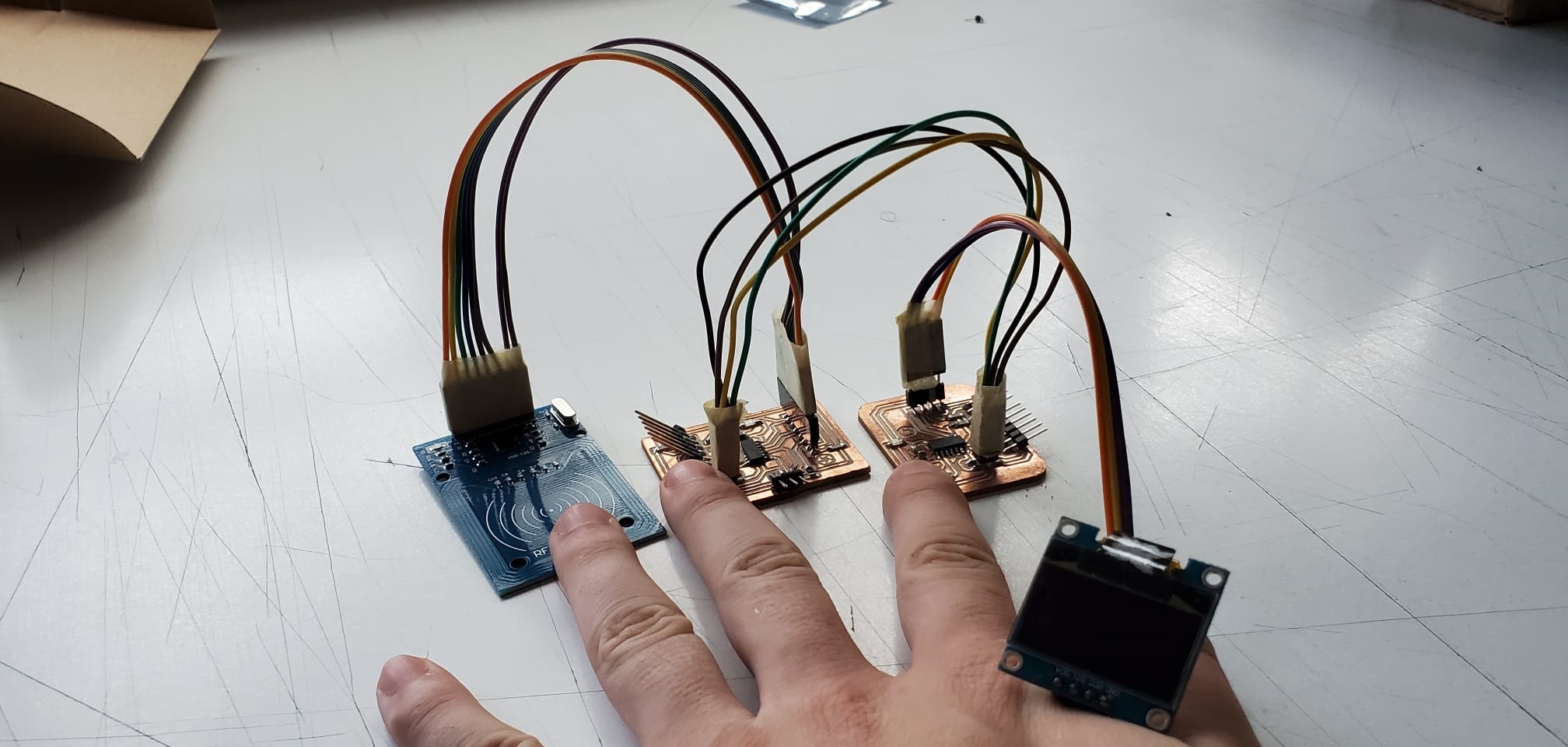
I originally wanted to connect it to the OLED board that you can see and download in in the Output Devices week
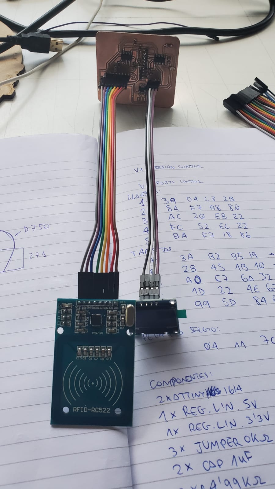
So when I could go back to the university, and after a little debugging session with professor Sergio Bemposta, we could finally send a message between our board and the computer:
At the beginning, I wanted to connect the RFID sensor to the OLED screen using a BUS cable, and depending on the reading of the sensor, I can display a message or another in the screen, and I did that. I could make the message shown in the screen.
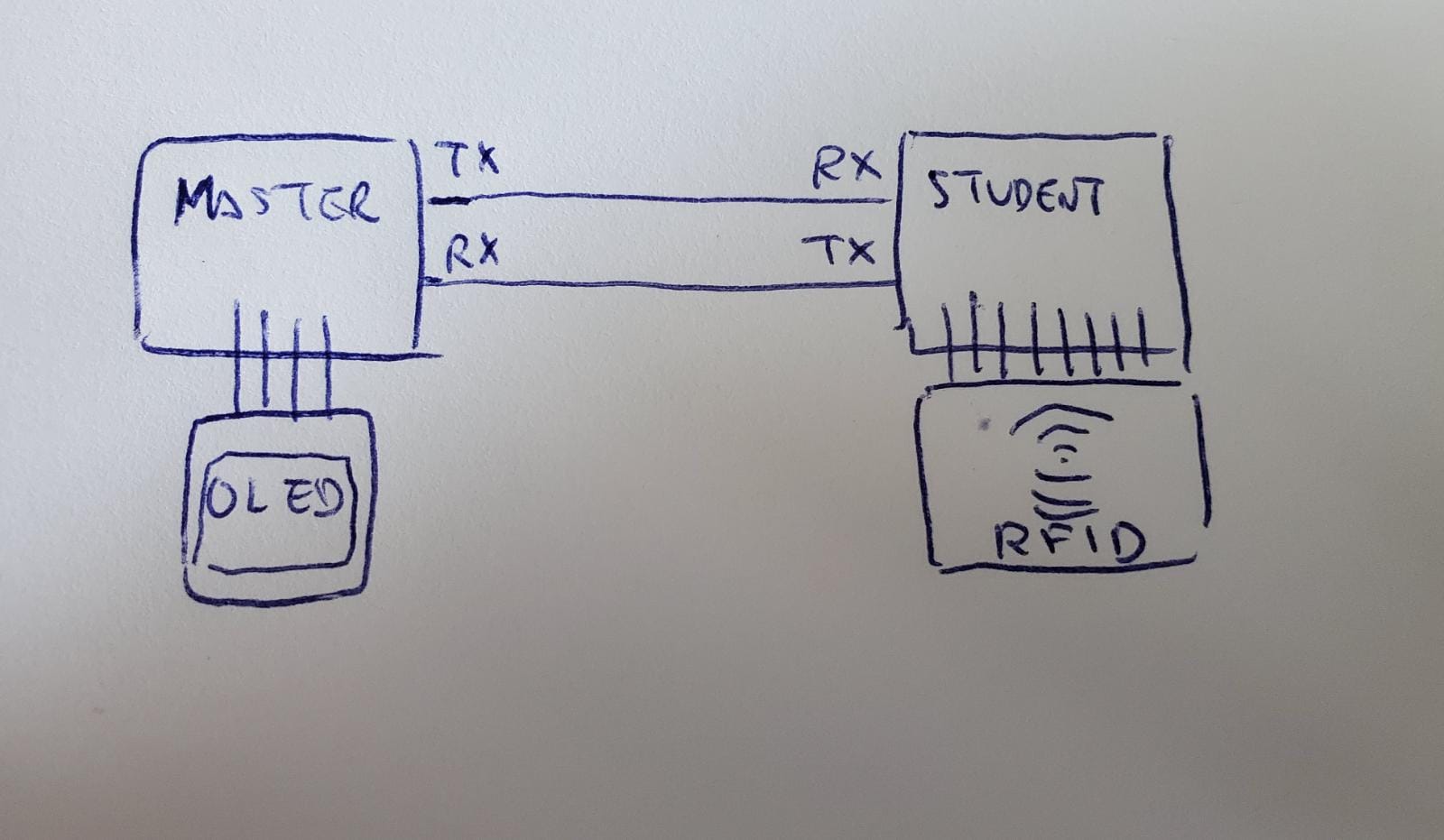
But in the end, and for the correct packaging of my final project, I ended up having both of the microcontrollers in the same board, and the BUS cable was actually milled in the board, looking like this:
You can get the schematic and outlines on the final board here:
The code was used in the final project, so here are the codes: