Input Devices
Welcome to the Input devices week in my FabAcademy! This was for me the most mentally challenging, phisically exhausting and psychologically destroying of them all, at least up to this point. The triage decision was tough to make, some microcontrollers were destroyed, Nuria’s sensor was destroyed as well. The fact that I’m actually being able to document something is a win for me, so follow me on this week’s assignment, learn from my failures, and please, be mercyful.
I always say that every week in FabAcademy there are three things to do. Number one: complete the assignment. Number two: learn something new. And number three: make something either awesome or useful. For example, in my 3D printing week, I printed part of my final Project, that was useful. Fort he electronics programming week I did the Gigi d’Agostino light show with Fran’s video, that was awesome (in the sense that I had so much fun doing it)
This week I wanted to do something useful and have as an input an RFID sensor, the RFID-RC522. Nuria kindly had one shipped to me from León. I short-circuited Nuria's sensor. I lost all my work as my computer suddenly shut down without saving. I broke my favorite endmill by accidentally milling the Z probe. I need a holiday.
as I like to document as telling a story, this time the group assignment is down below.
Chapter One: work towards the final Project
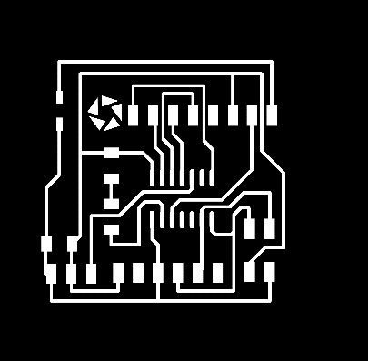
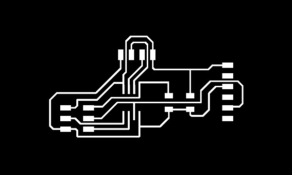
Disclaimer: this board was never completed. The original Eagle file was lost. The Schematic and Board files were never recovered. The PNG of the board is available, but useless, as you can’t know where the components should be soldered. A new board will be designed and milled as soon as possible.
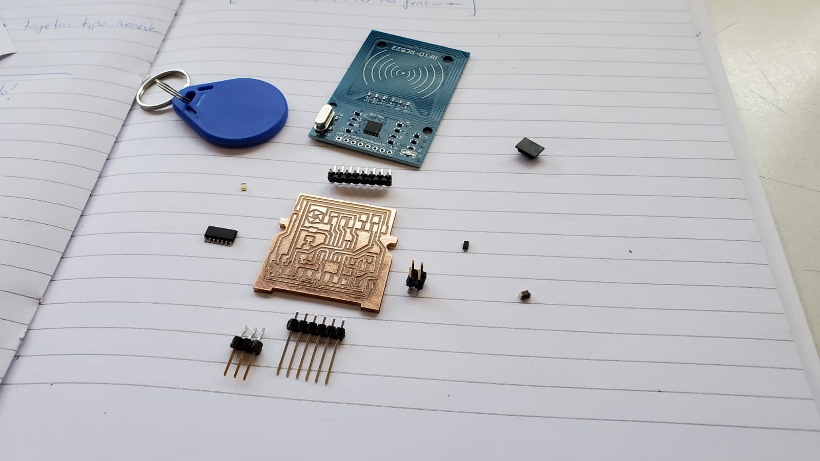
As for my final project I wanted my parts to store some information, so I needed a sensor to get some information from somewhere. Enter the RFID-RC522. It comes included with a keychain and a card that holds some information, and the RFID sensor can get the info from the card or the keychain, and then project it on the serial monitor.
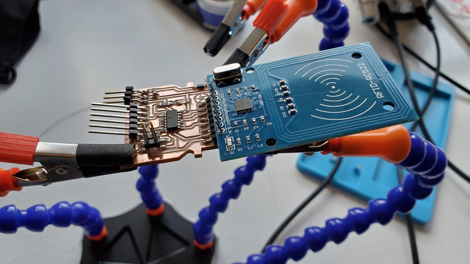
I used an ATTINY 1614 on my board, but in order to program it I needed an FTDI converter. Adrián has, for his Adrianino Project, a very useful converter that let you program your 1614 just from the FTDI to USB programmer. So together with Lorena, we milled a couple of boards, she soldered the resistors, and we were ready to design the board.
I designed my board with the shape of a truck that carries the RC552 sensor on top. All the connections were done similarly to Neil’s HelloFTDI board , except for one pin. The SDA pin, in Neil’s example, is sent to PA4 (SS) instead of PB1 (SDA) of the microcontroller. I wondered why it was sent to the “wrong pin” in the microcontroller, so I just did it the way it was most logical for me, and connected SDA to PB1 instead. I also added a 4 pin connector for BUS duties in the future, as Lorena and Adrián advised me, that could be useful for the networking and communications week.
I milled the board and soldered the components. I was proud of my work. It was time to upload a basic code and see how it worked. Oh how wrong I was.
Chapter two: how (not) to debug a multi-short-circuited board
I had another huge problem this week. I was being driven by pure faith, as the multimeter on my lab was stolen last week, and I still haven’t found it. I had to rely on my board design abilities, that are questionable. Obviously, when I connected the board to the computer, I was happy, as the LED on the top was on. What I did not know at that moment, is that it should not be on… My board was short circuited in different places. It did not work. It was Saturday night, the building was about to close, I needed a solution and I needed it quick... So I milled a new board and, as night fell, prayed for the best.
A quarter to 10 pm, just minutes before the building closed, I sneeked into the electronics club lab of my university and stole a multimeter. It was not _my_ multimeter, but it was _a_ multimeter. The following morning I measured the new board, and the result of the use of that tool was clear. I needed to mill a third board.
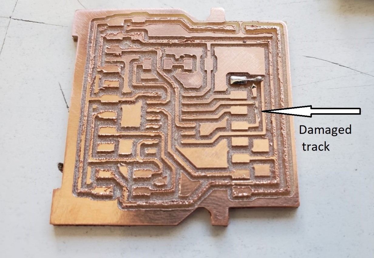
As I wanted to use the board on my final Project, the size of it was very small. So small, in fact, that was hard to solder and hard to fix its issues. When I soldered the second board, I found out that I had another short citrcuit, this time between IRQ and GND. When I tried to re-route the board, I found out that the Eagle file was missing from my computer. Egg on face. I had to start again. I did not have enough time. It was Sunday morning. The building closed at 3PM on Sundays. I needed to do something easy and quick. Enter the HC-SR04
Chapter three: triage
As I’ve told you before, there are three things that you have to do in a FabAcademy week. To complete the assignment is the most important one. The only way to do it was to create a very simple board, with a very simple sensor, a FabISP-friendly microcontroller and the stuff I had lying around. I decided that I had learnt some stuff, so I even if I was not going to be able to do something useful for my final project, at least I could have a usable board...
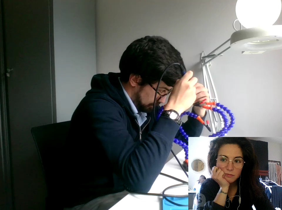
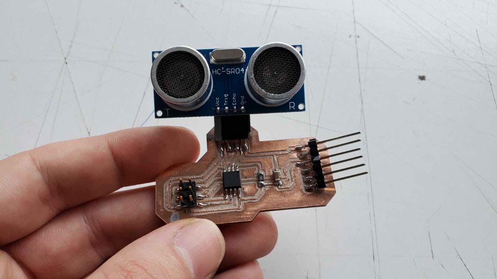
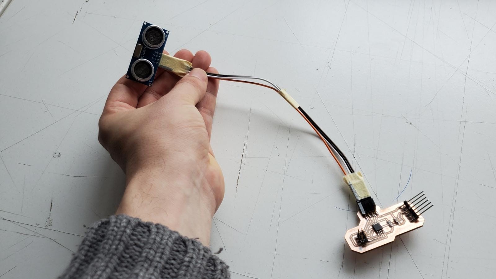
I got an ATTINY45, so I redesigned Neil’s example. This board is really simple. I pinned the echo and trigger, the FTDI and ISP connectors, and the only other things you need are a 1uF capacitor and a 10k resistor. The board was designed and milled relatively quickly, under the surveillance of my lovely girlfriend through a skype call. She did not look too impressed, though
I put it together and it was time to load a program and see how it worked
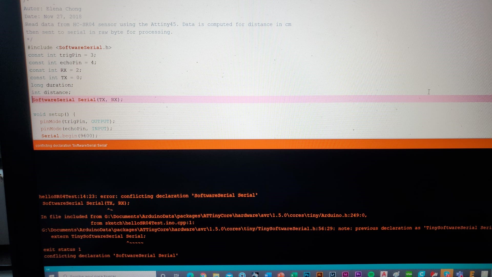
I programmed the ATTINY45 through my FabISP. I used different codes. Elena Chong Loo had a code for the ATTINY45, but it did not work on my board and I still don’t know why. The SoftwareSerial Serial (TX, RX) was giving me an error. Elena Cardiel did the same with an ATTINY 44, and her pinout was slightly different. I modified her code, and found that she was using SoftwareSerial Serial_Sonar (TX, RX). Also, when you program these sensors, remember that the clock on the ATTINY45 is 1MHz. I programmed the board and gave me no errors, then connected the FTDI cable and it was ready to go. I also recommend to connect a cable between the board and the sensor to improve the functionality and the freedom to move
But when I opened the Serial monitor, I found out that it was not displaying anything. This is because in the newer controllers you don’t need to specify the output, but on the older ones, you need to specify correctly TX and RX. In Elena’s code, RX was 1, but in my code, RX is 2.
Once I solved that little error, the sensor started to measure correctly.
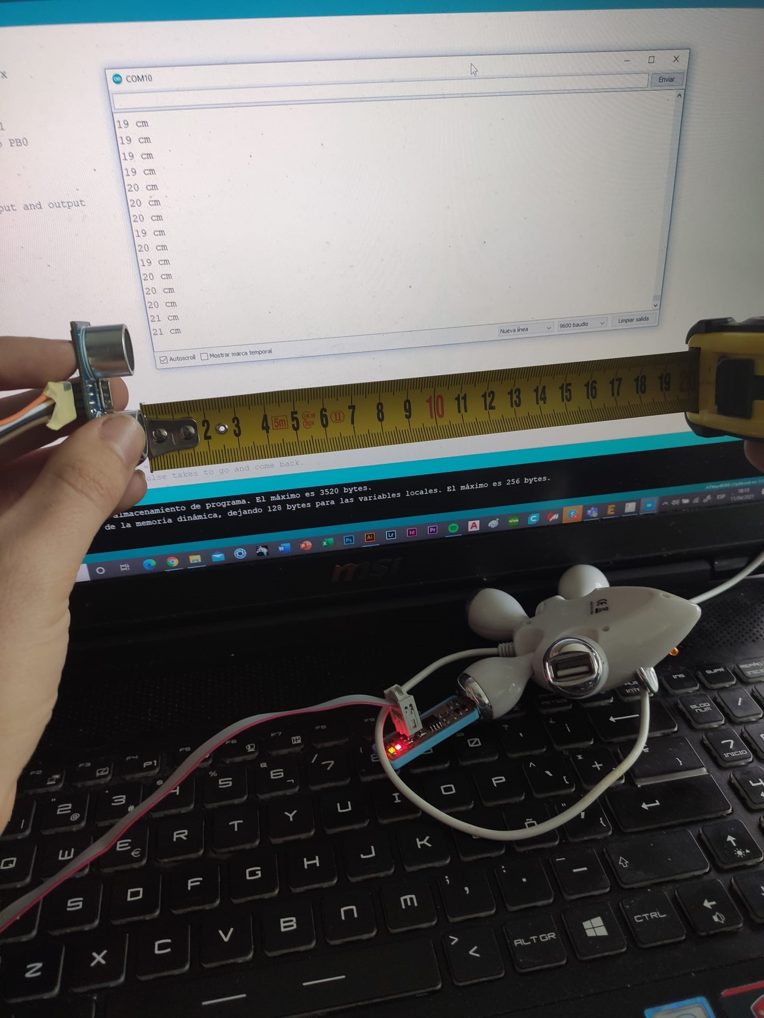
The accuracy of the sensor was not exactly amazing, but an error in +- 2 cm is acceptable
You can get the Eagle Board HERE.
You can get the Eagle Schematic HERE.
You can get the Arduino code HERE.
I therefore had completed the assignment, and learnt how to communicate with my Attiny. It was then time to use the oscilloscope and learn to read its signal
Group assignment: Oscilloscope
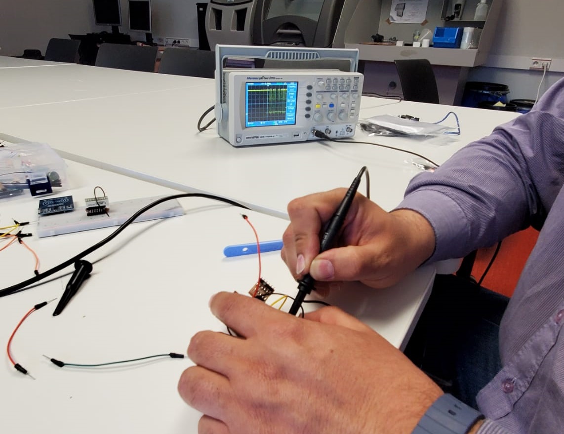
I've used the oscilloscope with the help of professor Sergio Bemposta, in the electronics lab, as we currently don't have an oscilloscope in the FabLab (we will soon). We used it to measure the difference in voltage (pulse width) as the ultrasonic sensor approached an object. Oscillations in the screen could be seen, and as soon as possible I'll document the utilization of our own oscilloscope.
In order for it to work, we place the two cables in the paths and we can modify the different functions to display in the screen. You can change the different scales by turning the different knobs.
And with this, this assignment is done. Sadly, I did not have more time to enjoy more kinds of input devices, but I will continue investigating these in my future FabAcademy journey