3D Scanning and Printing
Hello, FabAcademy friends! Welcome to what was going to be my favorite week of them all in FabAcademy, but turned out to be a week where I could not do everything I wanted to do. I'm actually getting used to it, but this week was specially hard, as I love 3D printing. I love to design for the machine, I love to put the machine to its limits and I love teaching 3D printing to my students. This is the week were I wanted to create many many things, and I ended up rushing to finish on time. Do you want to see how it went? Come with me
Chapter One: Group Assignment. Characterizing our printers
Here in FabLabUE we have a nice collection of printers. Available for all of our students to use, we have available six Creality Ender 5 and three Ender 5 Plus. Used only by the technicians, we have also some other resin printers that we still have to play with (and we will).
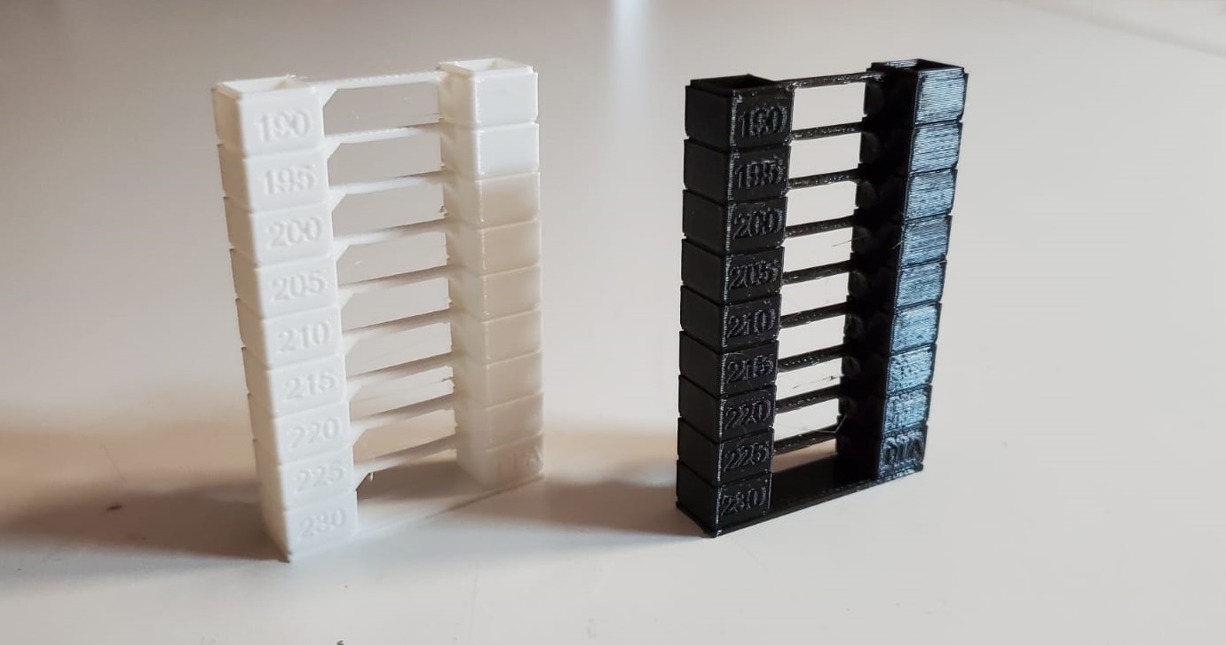
The main quality issue that our students find with their prints is the stringing. So we decided to start with some temperature towers to charachterize the materials we currently have available in the lab.
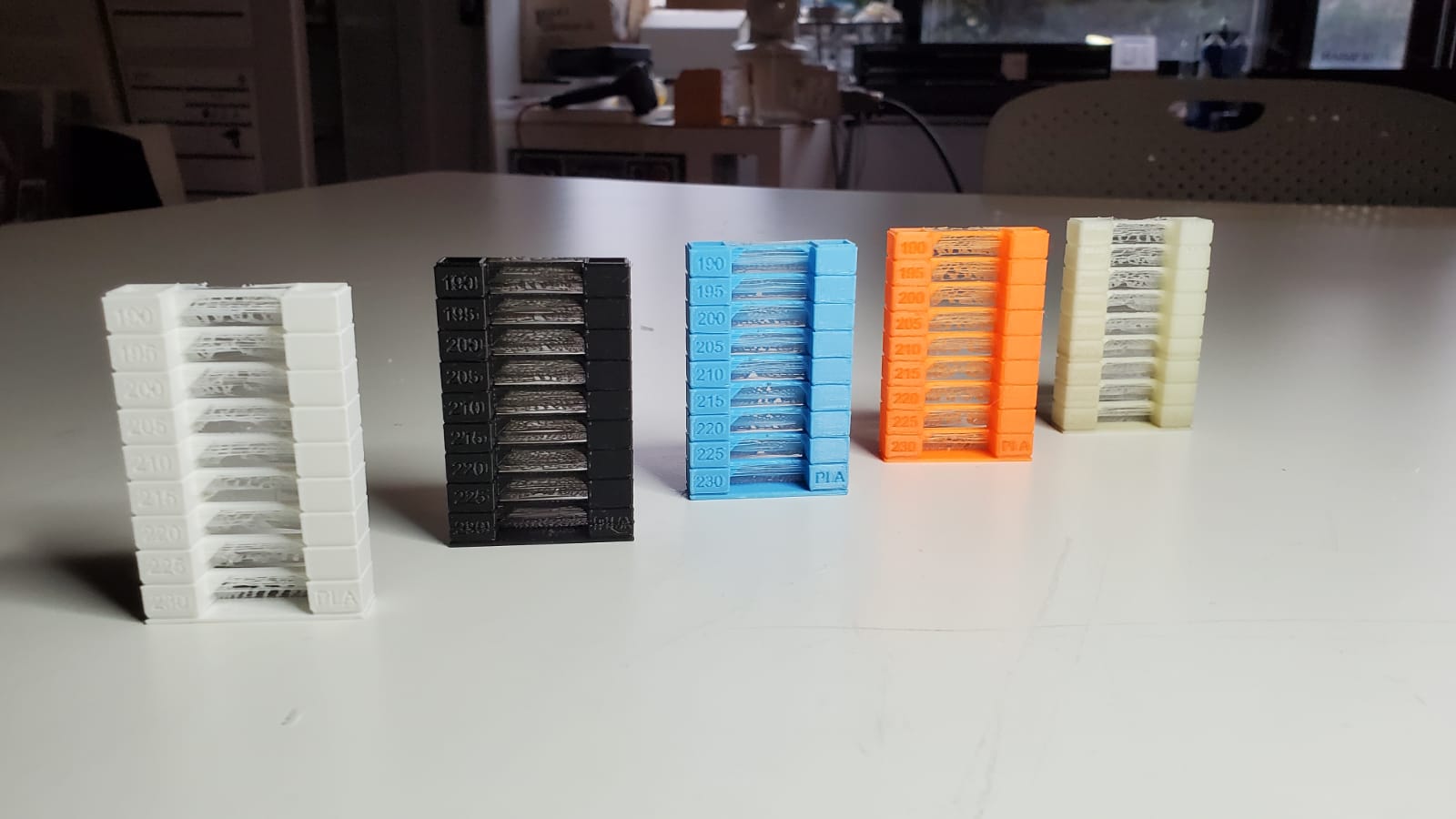
As all of the tests showed some kind of stringing, we went ahead and decided to print the specific 3D printing stringing test .
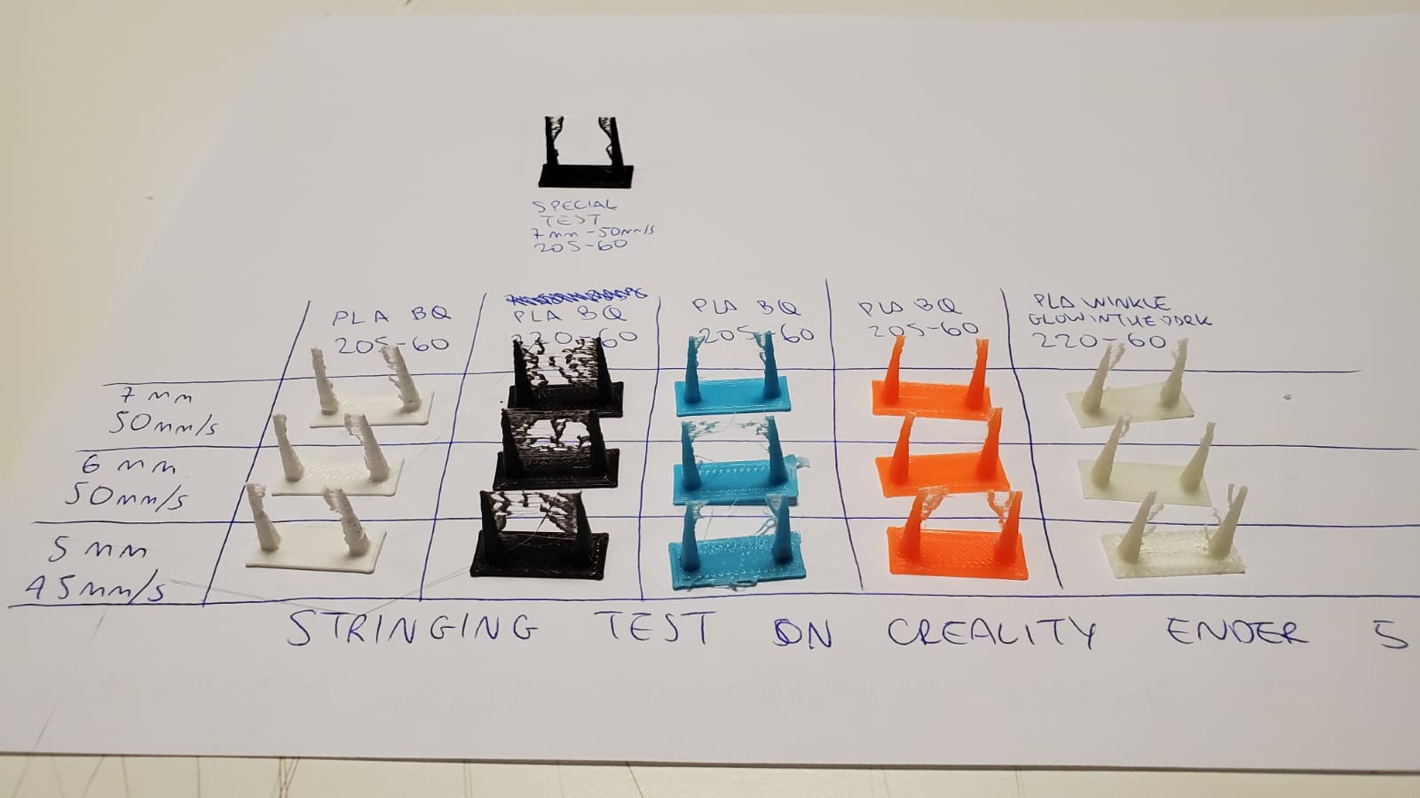
The results were amazing. So the same plastic (PLA), from the same brand (BQ Filament), with exactly the same printing parameters, just only different colours, showed different results. There is an explanation about this phenomenom. The additives that filaments have in order to get one or another color also change the characteristics of the filament, and therefore, its tendency to create more or less stringing. Our retraction settings were set then to 7 mm of retraction at 50mm/s, and our temperature towers came way nicer
So we went ahead and, with printed some of Marián Trpkos's 3D printer test. This universal torture test for FDM printers can throw terrible results sometimes, but our Creality Ender 5s managed to show their strength, with very nice XY definition and fantastic overhang performance
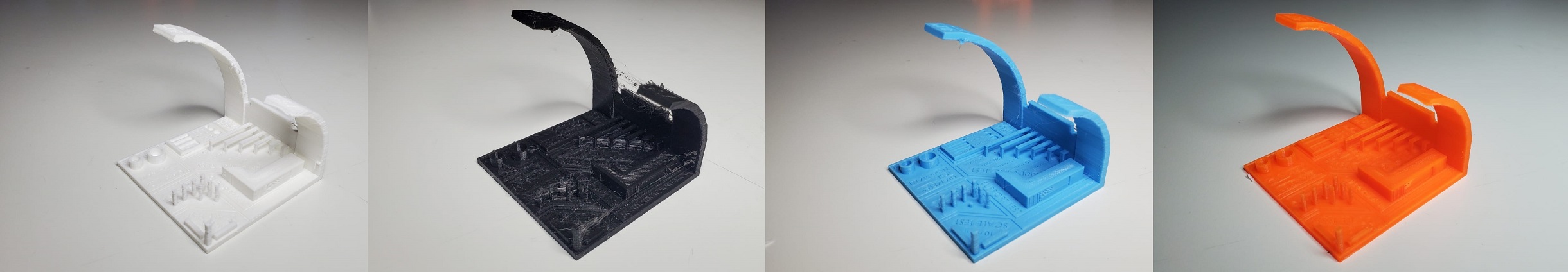
However, it was the orange BQ filament the one that looked the best. Great definition, almost zero stringing. We will use that filament for special parts in the future.
Also, 8 mm diameter test showed 7.9 mm, 6 mm diameter test was measured 5.9, the 1 mm bars were 1.05mm long, showed almost zero stringing and almost perfect bridging. It's a pity that BQ went bankrupt and we won't be able to buy this filament again.
Chapter Two: Additive manufacturing Only
So for this week's individual assignment we had to design and print a part that could only be created with additive manufacturing. As my final project is going to involve a 1/5 sized car,I decided to 3D print its wheels.
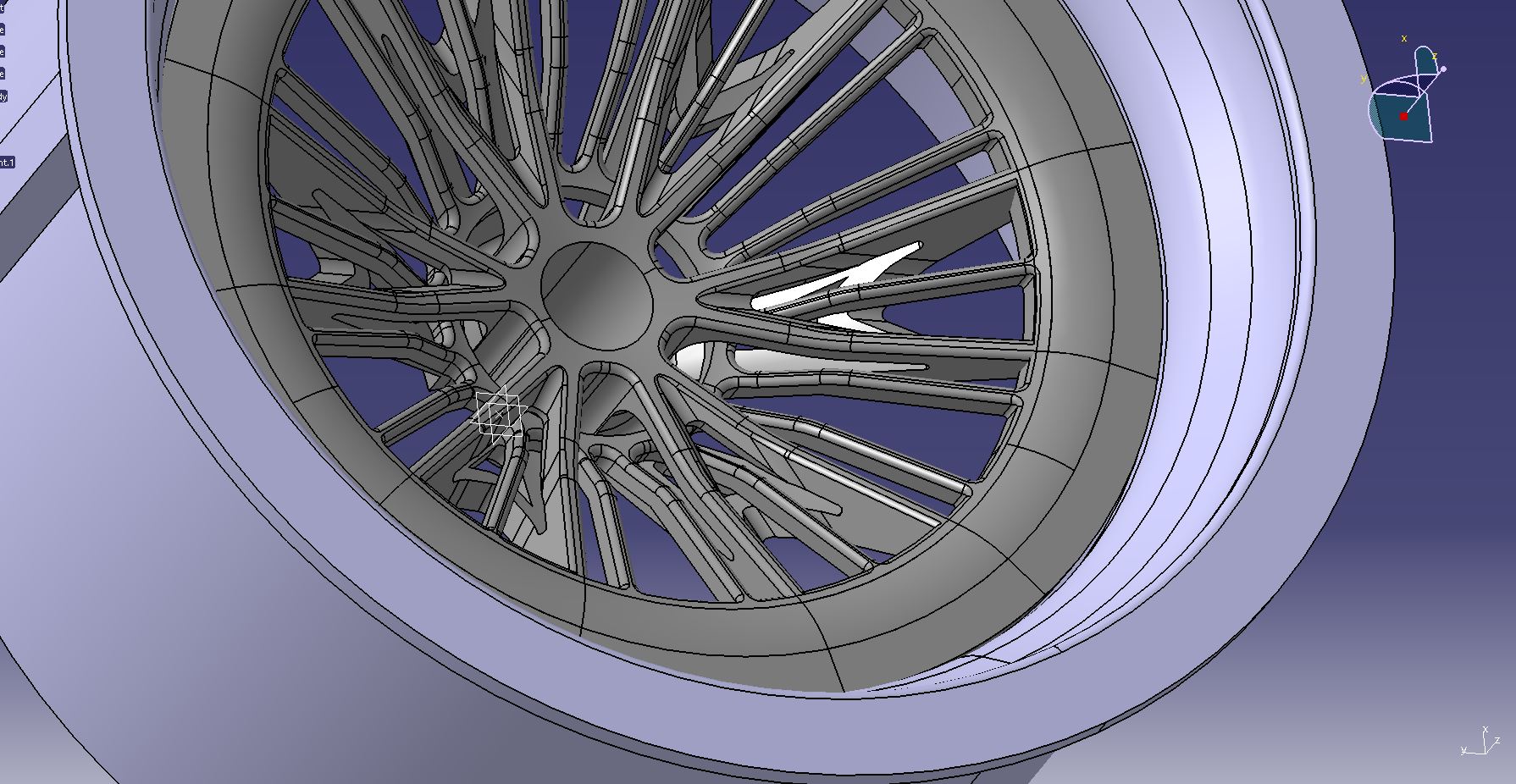
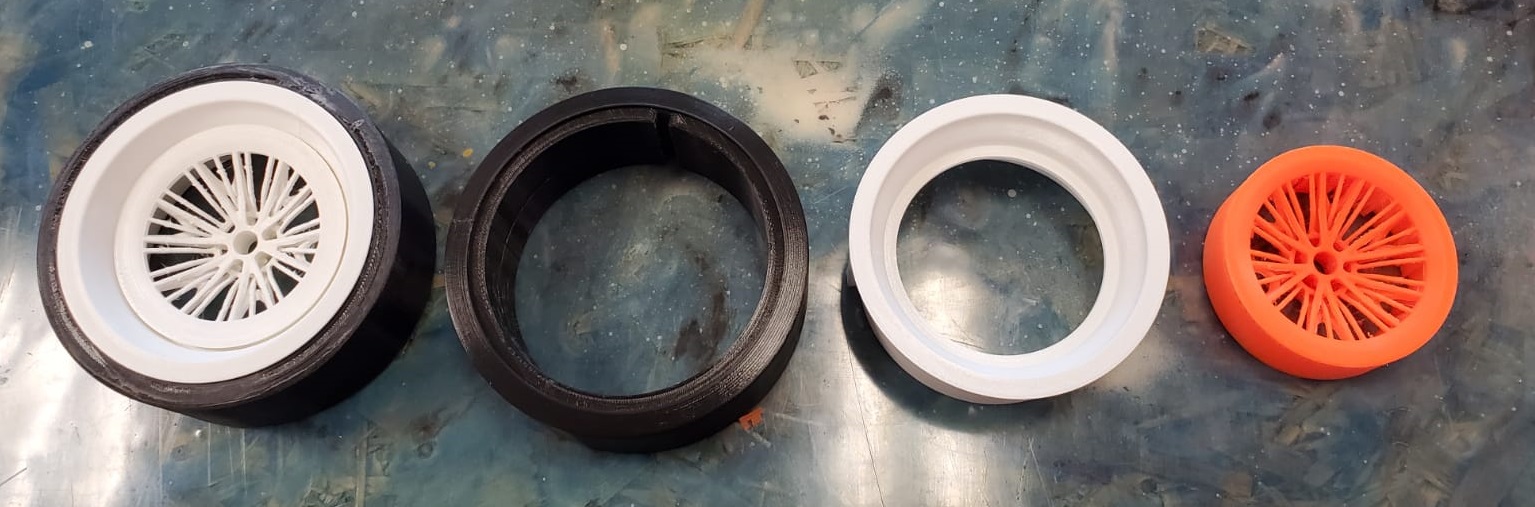
This is no ordinary wheel. In this wheel, the spokes are intertwined , so the only process available to make the design a reality is additive manufacturing. The wheel is designed in CATIA and has two parts, plus the tire, three in total: the external ring is called the barrell and the center part is called the face or center. My car is based off a Ferrari, and like the real car, is going to have a staggered wheel setup, this means that the rear wheels are wider and the front wheels are narrower. However, the center piece is the same in both the front and the rear rims, and the barrell and the tire are different
The wheel structure is a multibody. Parametric sketches are created in different planes and then the solids are created by revolutions and substractions. This way to design is more used in the industry compared to the freestyle - NURBS controlled surfaces I used in the Computer - Aided design week.
On this video I'm briefly talking about the CATIA operations tree and how this super complex design was created:
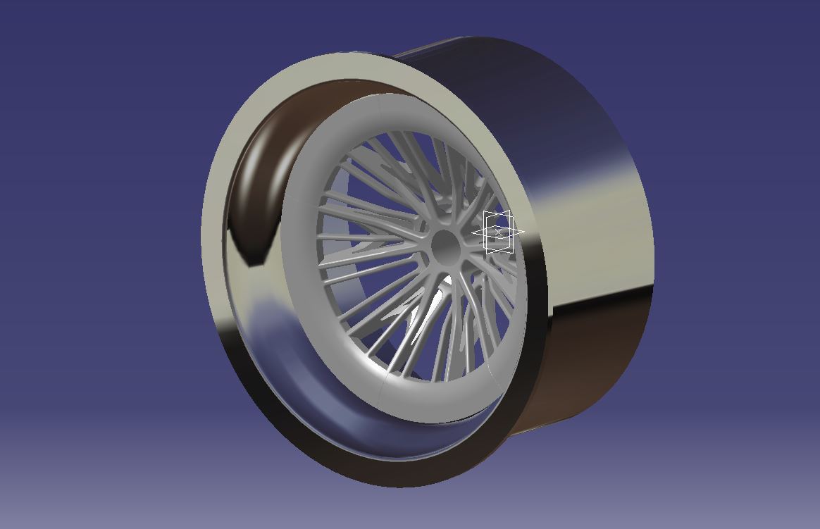
So as you can see, the wheel is made of these three parts. Each tire is about 12 hours of print, each barrell is about 14 hours of print (depending if it's the front or rear wheel) and the centers are about 13h, so the printing is going slowly, but at the end of this week I'll have the four wheels ready to paint and assembly.
In order for the wheel to be printable, the angles of the spokes were taken into consideration. As we saw before that the orange PLA was able to reach 75 degrees without falling, them I decided to have a 75 degrees limit on the design. However, for the center and the lip, the orange part needed a little bit of support around it.
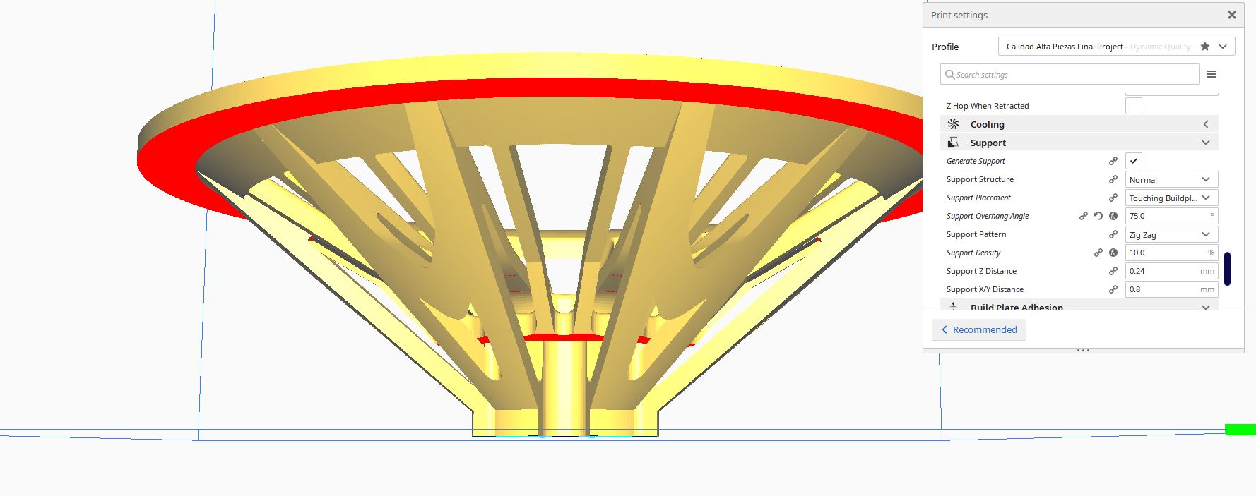
I also recommend you that, if you are printing a very complicated part like this one, with thin features like the intertwined spokes, lower the printing speed to 30 mm/s or even less!. Another tip is to check also the travel speed, very important but also very forgotten. I usually lower the travel speed under 70 mm/s when printing parts as complex as this with PLA.
So as you can see, the wheel is made of these three parts. Each tire is about 12 hours of print, each barrell is about 14 hours of print (depending if it's the front or rear wheel) and the centers are about 13h, so the printing is going slowly, but at the end of this week I'll have the four wheels ready to paint and assembly.
You can get the STL of the front barrell HERE.
You can get the STL of the front tire HERE.
As the wheel center is too big, I've uploaded to my sketchfab account
Bonus: Let's print the car
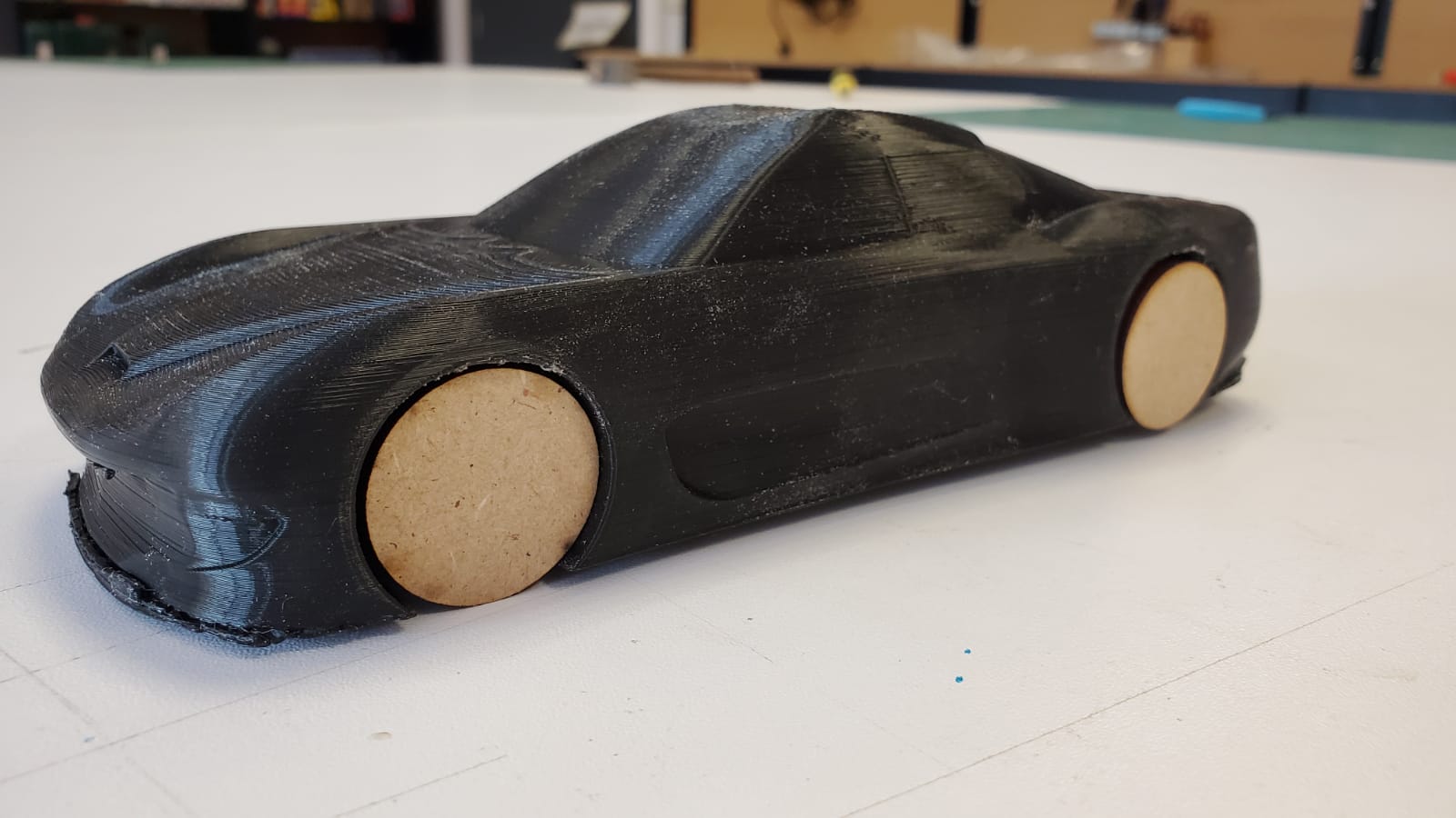
As we I was already with the momentum, I created the version One of my final project, I 3D printed the body of the car I want to create in 1/5 scale with interchangeable parts, but this time in 1/24 scale and in one piece. Ready? Let's go!
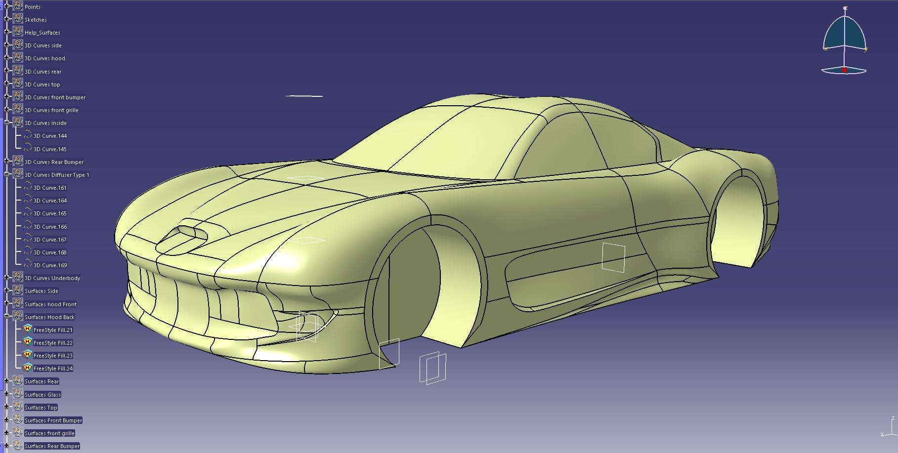
First of all we need to create a printable body in CATIA, so we need to close all the surfaces and join them together. Then, we scale the result to the real scale of the model that we are going to print, and through the STL Rapid Prototyping workbench of CATIA, the shape is created. Time to sent it to the printer through Cura
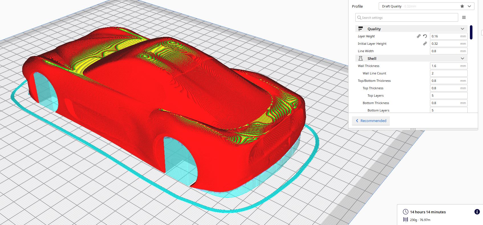
I printed it with the 0.8 mm nozzle but adjusted the layer height, as I did not want a super rough model, I wanted something relatively fine.. You can see the results in the pictures down below.
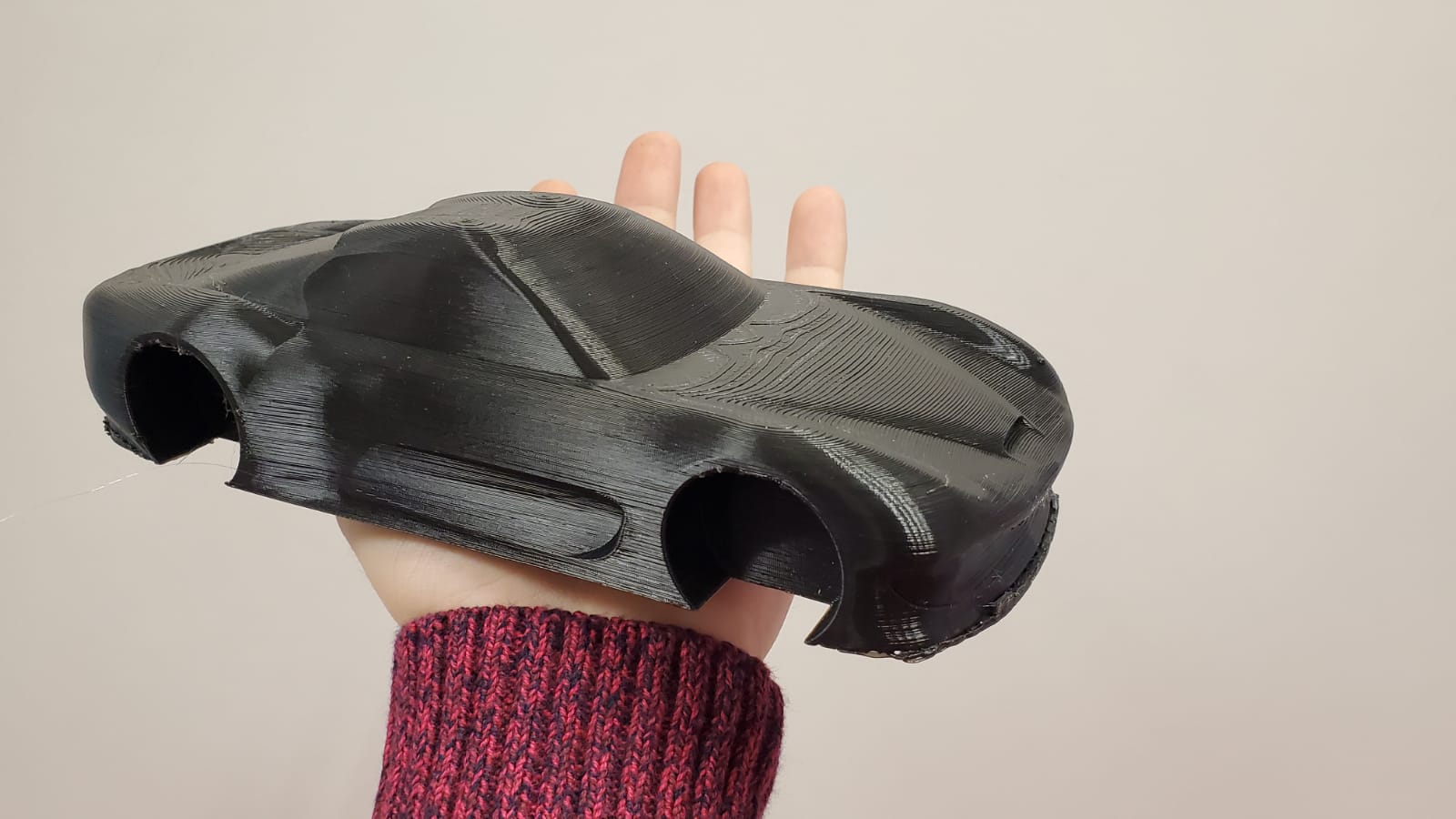
I laser cut a couple of circles with MDF, just to see how it woud fit. I like the model but it served its purpose, and now I want to redesign a little bit the proportions of the car to make it better looking and more similar to the car I'm using as a base.
As my STL is so heavy it can't be in the repo, here's the last version (the final project one) on SketchFab
Chapter Three: Scanning is hard
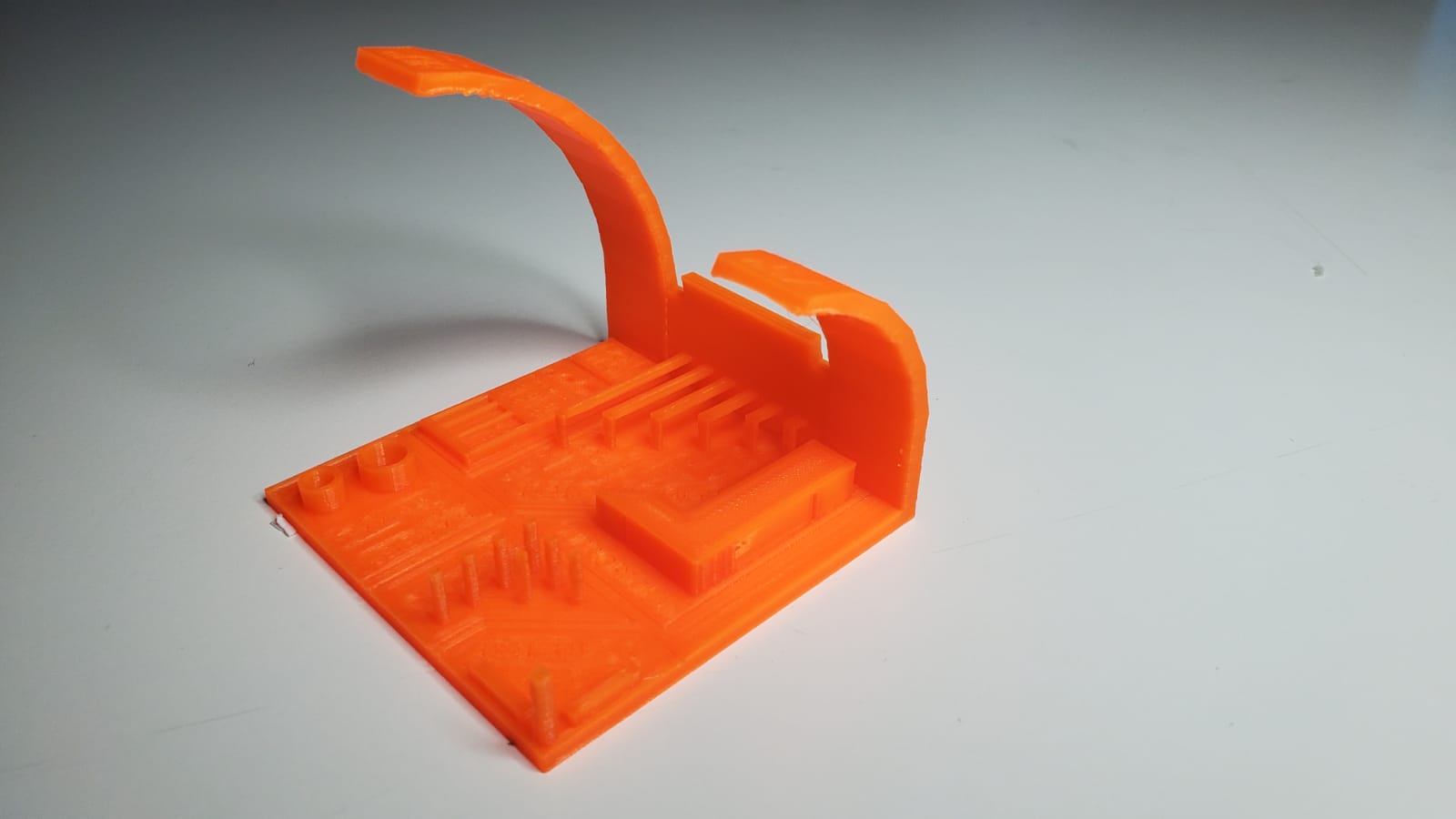
And for the last part of this assiggnment, it was time to use the 3D scanner. I had a 3D systems Sense lying around in the lab, and my colleagues said me that it achieved good result in the past. So let's give it a go.
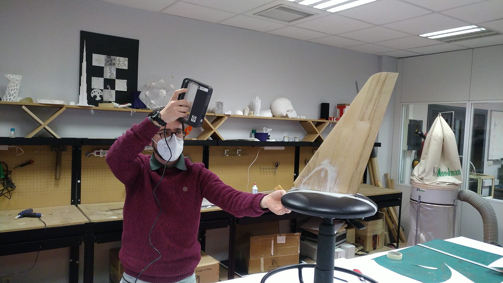
I decided to scan a plane tail that was 3D milled for a previous project and I had in the university. As a recommendation, try to scan in an empty space, and if it's possible, fix the object to scan to a rotating surface. I had a stool, and with that and a sense software, we were ready to scan.
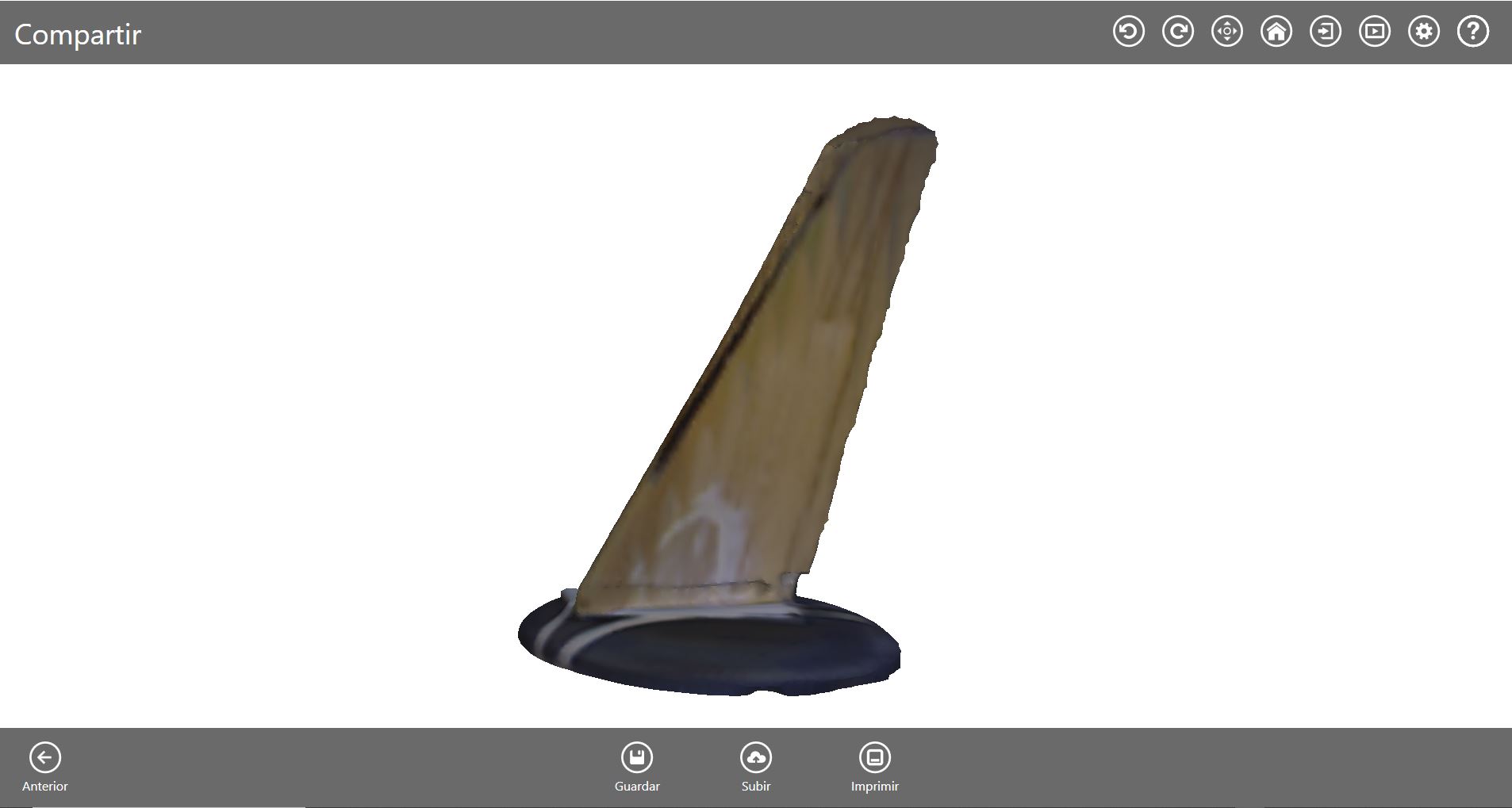
The definition is far from great, but it could be a relatively good base for reverse engineering. The sense software also has a "Solidify" tool, so the part you scan can be easily printable
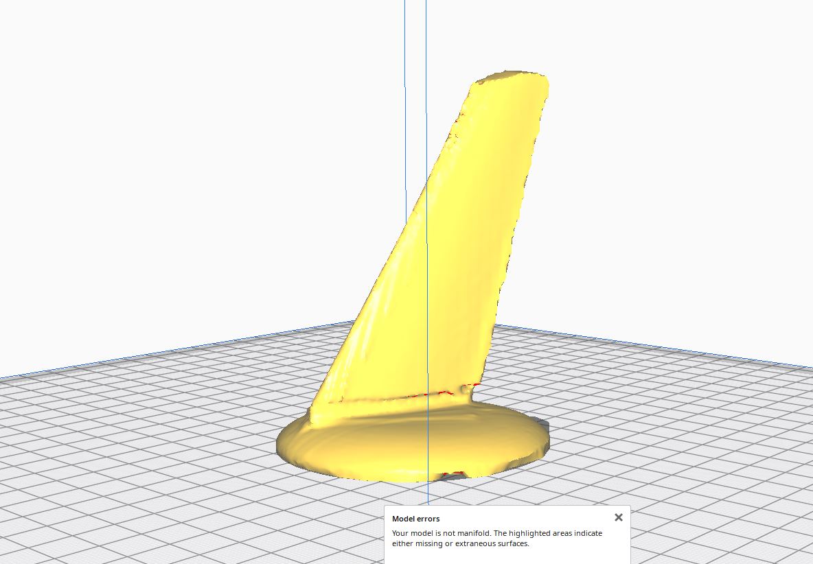
I haven't printed it yet, and I honestly don't think it's worth it. However, I think this technology is a must in a FabLab. It does not work everytime, but when it does, it can save a lot of time.
So this is the end for this week. I would like to do many more things, but for now, this is it. We will continue working on 3D printing in the future.