Computer-Controlled Cutting
Welcome to another week of my FabAcademy! This week we're using two amazing machines: the vinyl cutter and the laser cutter. It's a week that I'm enjoying a lot, because even if I have some experience with this kind of machines, it helped me try some techniques that I've never tested before. The vinyl cutter is probably one of the most underrated machines in any FabLab I've ever been to. Actually, the last big task I had in FabLab Nebrija where I used to work was to design and wrap the livery of the Nebrija Power Wheelie, the race bike that some of my students were building as a Univerity project, that was presented in Aula, the most important University fair in Spain, where I also had the opportunty to display my thesis However, I've used the vinyl cutter in other cool projects, too... But let's start with the group assignment first.
GROUP ASSIGNMENT PART ONE: BE STUDENT FRIENDLY
for this group assignment the task was to characterize our laser cutter parameters for a number of materials. However, as the FabLabUE belongs to a university, I'd like to show our methodology. We try to do this with all of our machines, as we have a library of endmills on the CNC, and some well-tested Cura profiles for our 3D printers.
In the particular case of the laser cutter, we have a library of material settings. These settings can be adjusted during the lifetime of the machine, because as the laser tube degrades over time, some parameters may be changed, but what usually happens is that every time a technician is going to use the laser, they double check the parameters and we update the library as we go.
After one year, this is how the library looks:
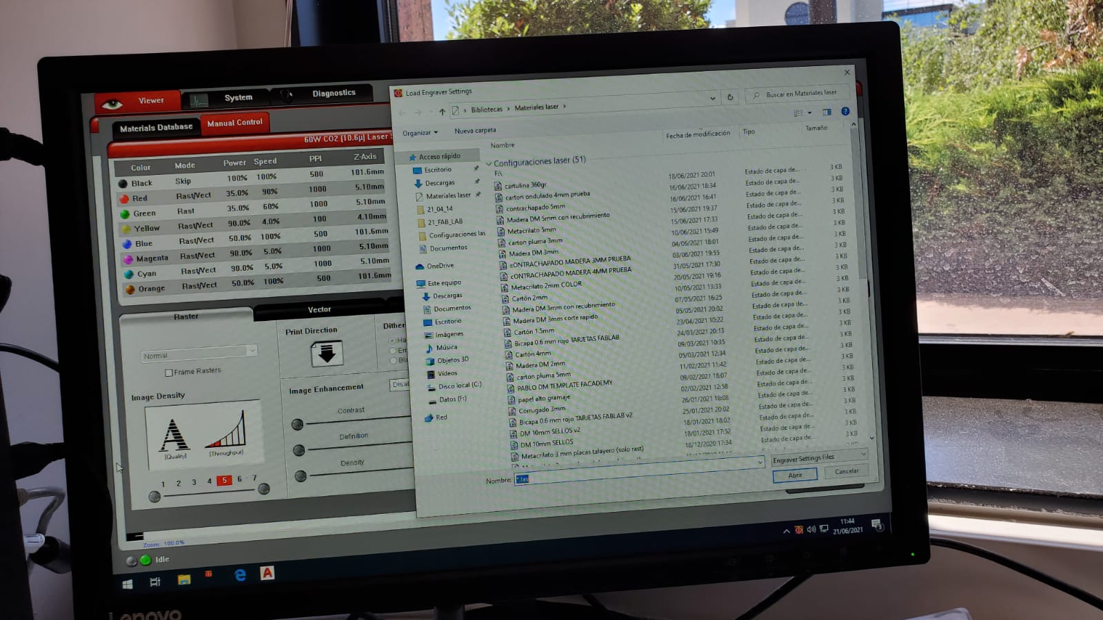
When students or teachers come to use the machine, they just have to select the material that they are going to use, and it almost always work (sometimes they bring bent boards, or they select the wrong material thickness, but in general everyone is happy with this methodology.
THE ROLAND GS24 AS THE MACHINE THAT I MADE MY NAME AND BRAND WITH
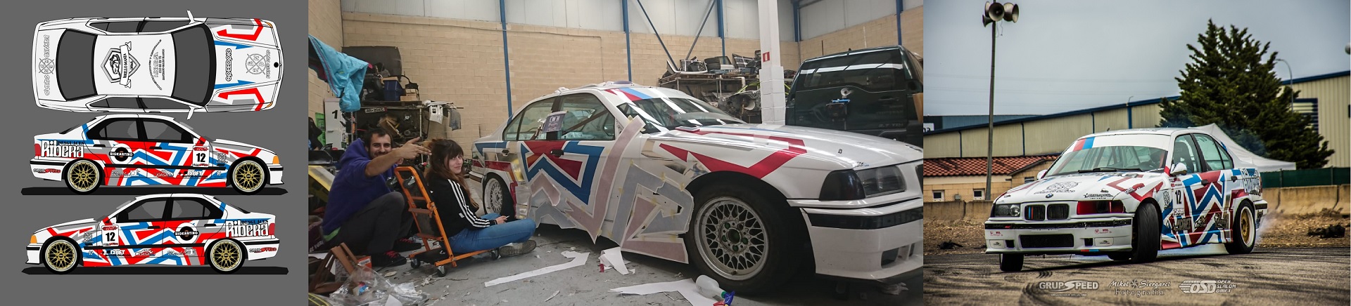
Now let's get back to the story. Who said that It's impossible to design and wrap a full race car livery with a 60 mm wide vinyl cutter? It's definitely hard, but with a little bit of help from some friends, that's exactly what we did. Most car wrappers in Spain still refuse to take those jobs. We prove them wrong. I've had my signature in liveries that have been used by Drift racers in the national Spanish championship. But Aitor Galán, the champion in the amateur category and his team, decided that they needed a striking wrap, with chrome and matt colors. They had very little money, but one of their sponsors, owner of a small custom t-shirt shop, had a Roland GS-24. So I designed the livery with Adobe Illustrator in the university, send them the files, and they just had to press Play. Aitor, Iker and Yaiza set to work, and after many hours putting the puzzle together, the livery debuted in Miranda de Ebro and has been Aitor's signature since.
So, what are the steps to prepare a file from Illustrator to the Roland GS-24? The main problem is that the design goes further up in the roll instead of printing in the part where the origin has been set. There has to be a way to place the design exactly where you want, right?
GROUP ASSIGNMENT PART TWO: THE ILLUSTRATOR-TO-ROLAND METHODOLOGY AND COMMUNICATION
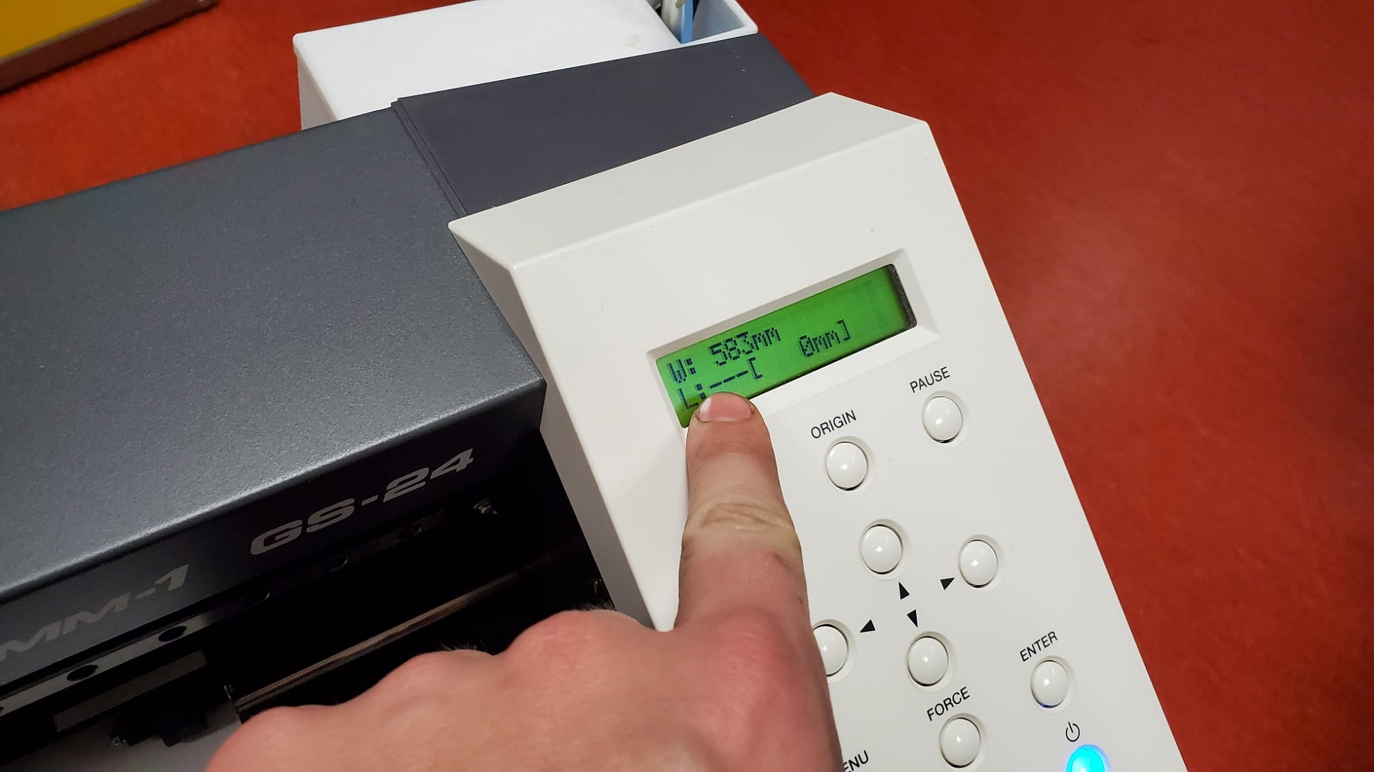
Once you know how to design a little sticker, then it's easy to do a whole race car, so I'm going to start with the basics and I'm going to show how I prepare the files straight from Illustrator to the Roland. The first thing you will need to do is install the printer drivers, that you can do here. Now the Roland GS-24 will appear as a printer when you click on File -> Print on Illustrator (By the way I'm using Windows so I don't actually know if this will work on Mac or Linux). Now it's time to go to your Roland GS-24, load the roll and do a test. Always perform a test before cutting. Even because the blade degrades over time, you may have to adjust the parameters of the cutter.
Now check the width of the roll on the machine. It's super important as it will give us the width of the artboard. Create a new artboard with that width and the length of the vinyl roll that you're working with, and then paste your design on the new file. Remember that all of the lines should have no stroke width or you will mess up the cut.
Also remember that the design should be in vector form (if it does not come from Illustrator you can try to do an image trace, but I'm not going to show that now) and in the real measurements, exactly as you want your sticker to be cut. Always measure twice, and cut only once
And now the magical steps. With the roll properly placed and alligned, the USB cable connected to the computer, Follow the video to send the file to the machine
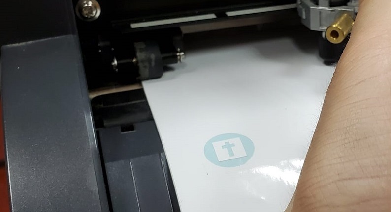
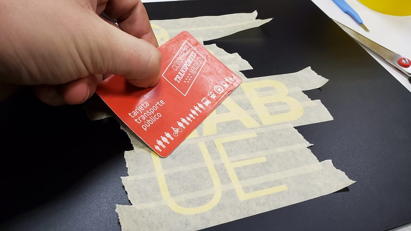
Now let the machine do its job, and you will have your sticker cut. Peeling the negative of what you actually want can be a mess, especially if you're dealing with very little details on your design. Bad quality masking tape can actually be a great transfer, as then you can remove it line by line. Make sure it sticks properly with a card, and then peel the tape.
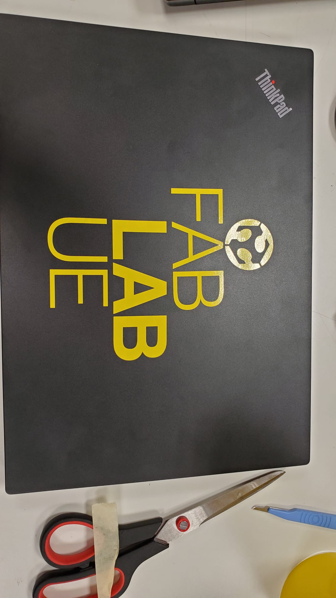
Now you can have your customized computer!
You can get the FabLabUE logo on SVG file here.
I just hope I could have a bit more time available on monday and tuesday to try to have a similar methodology from Inkscape and also try the Shilouette Cameo that we also have in the lab!
THE LASER: MAYBE OVERRATED, BUT LIVING UP TO THE HYPE
I'm a lucky guy who has worked in two amazing labs, I used to have Trotec machines when I worked in Nebrija, but in FabLabUE we have Universal. These are like the two biggest names as laser brands go, and these are very advanced, very expensive machines that can cost the prize of entire labs. I found Trotec machines to be more reliable, but Universal ones are more "student fiendly", as the software is easier to use. I've always launched the designs to the machine via AutoCAD and then through the machine's own software. With Universal, it's called UCP, and it's pretty nice.
We started doing some test in the lab. Living hinges and different power and speed settings. We got the living hinges from here
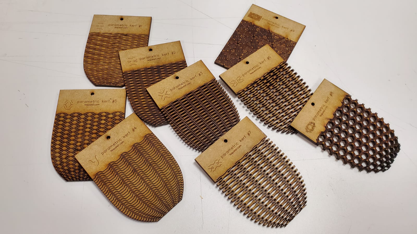
It was the first time I tested them with 4mm thick MD wood, and I was not as disappointed as I thought I was going to be. I only cracked one of nine when I tried to bend them. So now we moved into the new thing (for me): Engraving (rastering) pictures with the laser. This is awesome! This is a very easy technique to use when we make prizes, presents or in particular models, and the results are very spectacular for the people who does not know how it's made. So I tested different settings
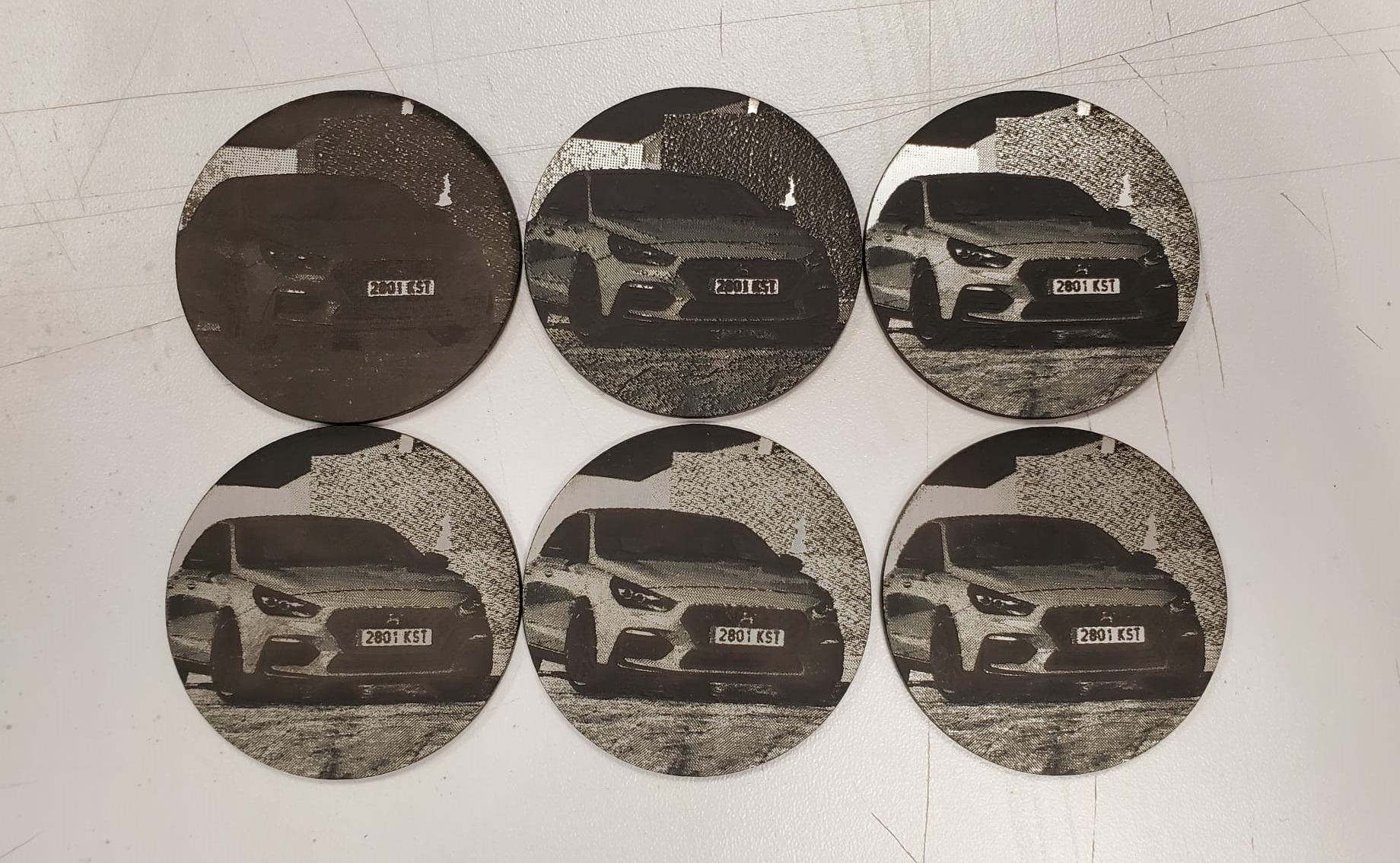
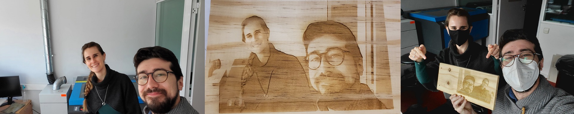
I found that the best resolution was achieved at 1000 ppi, don't know why, as I was told that more than 600 is usually counter productive, but this is what happened to me on that particular material. So as I was with my lovely new friend and fellow León remote FabAcademy student Lorena, we took a pic together and engraved it on wood. She came to FabLab UE to work on the assignment on Saturday, and it was the first time we actually saw each other in person. She taught me a lot about biomaterials so if you are as new to that as I was, check out her page!
(disclaimer: we only took out our masks for the picture, as one of the masks was white and the other was black, being that terrible for the color mapping of the pic, and we mantained the social distance of 1.5m for those few seconds. Always follow your FabLab code, use the face mask, keep the distance, and remember to sanitize!)
Now it was time to do the main part of the assignment: the press-fit construction kit. For this matter I used FreeCAD. We've covered that software already, my favorite characteristic of it is of course how easy it is to create simple parametric parts. It seems like the assignment is designed to be done with this software.
It's fantastic how it works! It's very easy to add and modify the parameters, and for any design that may vary with time of simple tridimensional or bidimensional parts, I reccomend using this software. If you want to hear my voice as I explain it a little bit, there we have it
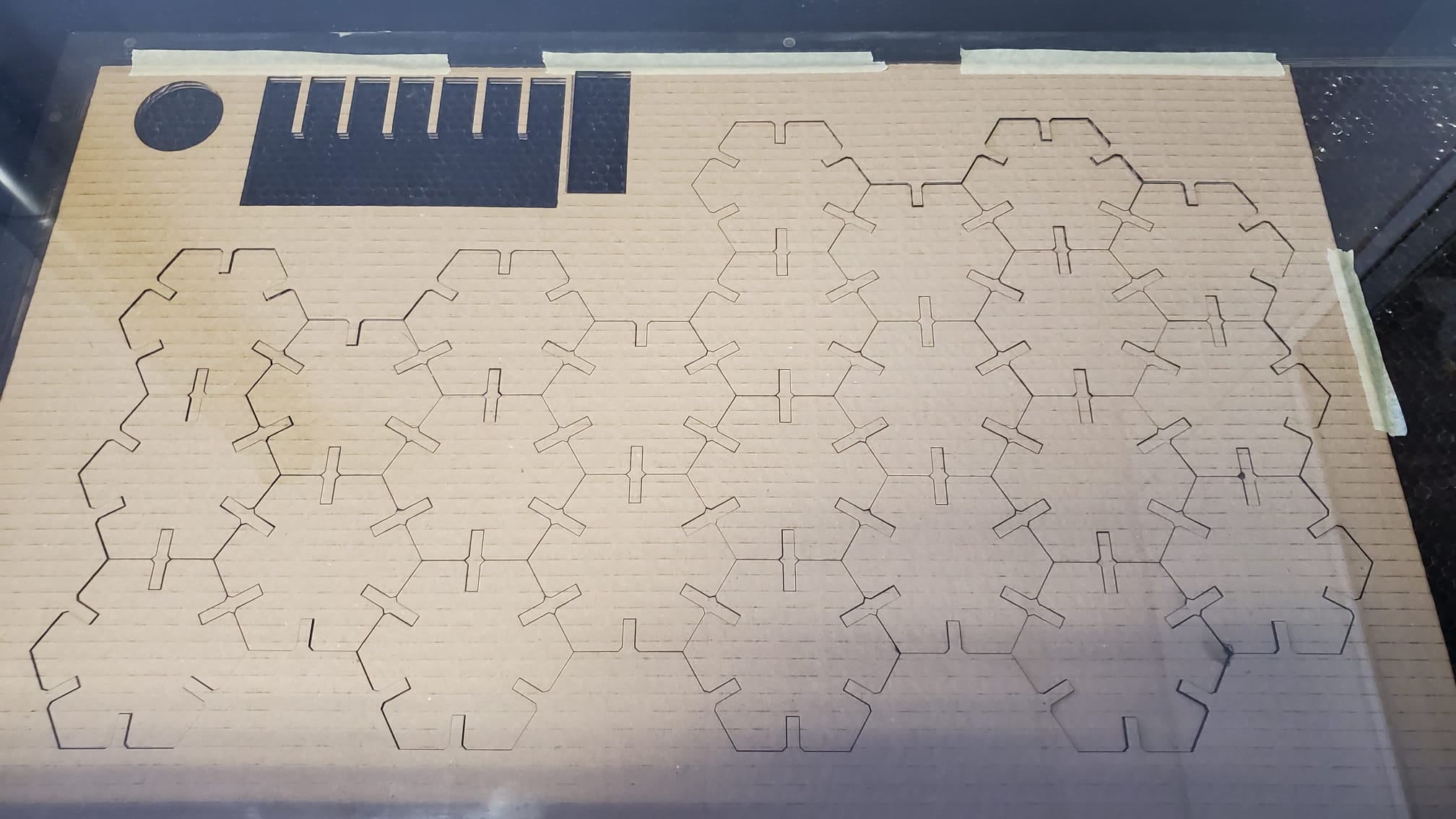
Once you have settled to the physical dimensions, you can export the bidimensional faces as DWG or DXF. That is copied and pasted in the AutoCAD file that we use as a template in my FabLab. The template is just a representation of the laser machine bed, scale 1:1 in milimeters, that has the layer properties already prepared with the correct line type, width and color so the laser will always interpret the design properly, and in the laser controller software you can change the laser specific parameters (speed, power, etc) according to the different layer properties to achieve the desired effect (cut, engrave or raster).
I used 80% of power, 9% speed and a 6.1 mm offset at 1.000ppi to achieve this result
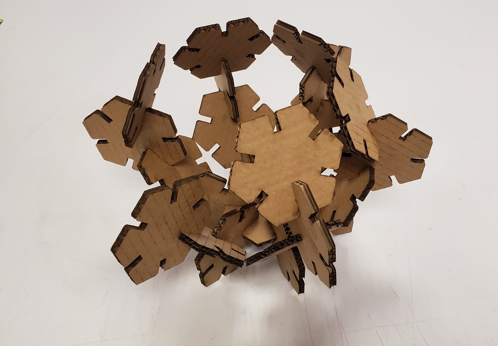
I tried different combinations, but here's a timelapse of a build that I made!
I really believe that the parametric press-fit construction kit is a very useful demonstration of how to go from bidimensional to tridimensional models, but it just scratches the surface of what the machine can actually do. The potential of this machine is something I'm willing to investigate more in the future, but for now, unfortunately (or fortunately) my job as FabLab Coordinator does not let me have enough time for experimentation.
You can get the original FreeCAD file here.
You can get the non-parametric DWG file here.
You can get the non-parametric DXF file here.
You can get the non-parametric SVG file here.
And that's it for this week, basically! I enjoyed this assignment a lot, but next week, electronics production, it's when the things are going to get serious!