Computer-Aided Design
Welcome back to my FabAcademy diary! This week our assignment was to design and 3D model our potential final project. I have some previous experience with 3D modeling, so I thought the week was going to be easy. Again, wrong. I really thought I was going to be able to test and try many different softwares but in the end I only had time to test one of the parts on the new software and the other part on a software I already had experience with. So let's begin.
2D drawing on open source programs, that's new for me!
The only 2D free program I've used to draw and design is Microsoft Paint when I was a kid. When I was in high school they taught me AutoCAD and I have never looked back. Then, in university, I discovered Adobe, and fell in love again. Since then, I gained some experience, both in raster and vector type 2D files, with Photoshop, Illustrator and Lightroom as I have my university license, I absolutely love the three softwares, and I love what I've done in the past. I've designed race car liveries for real cars that have won real championships, and drawed many concept cars that only lived in my life before, as well as some photo edits that have been used in posters. I've designed some posters, too.
Completely biased by my previous experience, I really thought that free 2D programs were going to be just bad versions of commercial softwares, but I decided to briefly try Inkscape. Inkscape is a freely available cross-platform vector design software, kind of like Illustrator but for free. In thought I was going to hate it, but actually, I liked it!
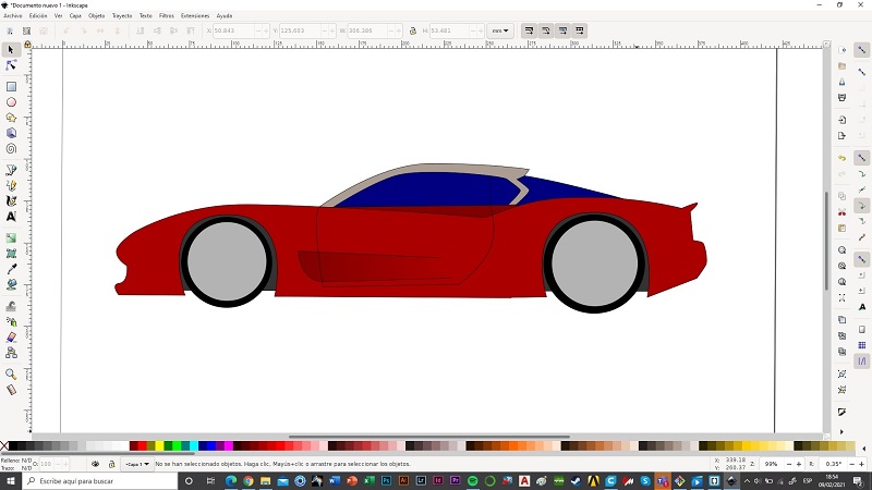
I thought it was going to be very limited, but I could get used to it very quckly, creating a rough vector model of the car I want to design for my final project, that I can now engrave with the laser or cut it on vinyl. I still think that Illustrator makes me more productive, but just because I've been working with it for much more time! definitely this is a free tool completely worth the time to master, and can't wait to use it for future projects with my students.
3D design, my favorite part of digital manufacturing
For this week's 3D assignment, I've compared two 3D softwares: FreeCAD and CATIA. Obviously one is a freely available cross-plattform great software for beginners and the other one is the software used by companies like Airbus to make planes, Morgan to make cars or RTTE to make trains. The license is expensive, but thanks to the universties I've always had access to a computer with CATIA, when I was a student and now as the FabLab coordinator. I may be a bit biased but I absolutely love this software to the point that my ex-girlfriend used to say that CATIA was the name of my lover, as I usually said to her "can't talk right now, I'm with CATIA". The work is still in progress, but I'll show you some of the advantages further down, as I'm using a module that not many people use on a daily basis.
The surprise: FreeCAD is awesome, but it's not good enough for me
But let's start with the new contender. Let's talk FreeCAD. Once I downloaded the 0.18 version, I discovered, in a mixture of relief and sadness, that is kind of a mixture of CATIA and SolidWorks, but uglier and with less features freely available for everybody to use, which is an amazing way to start using CAD.
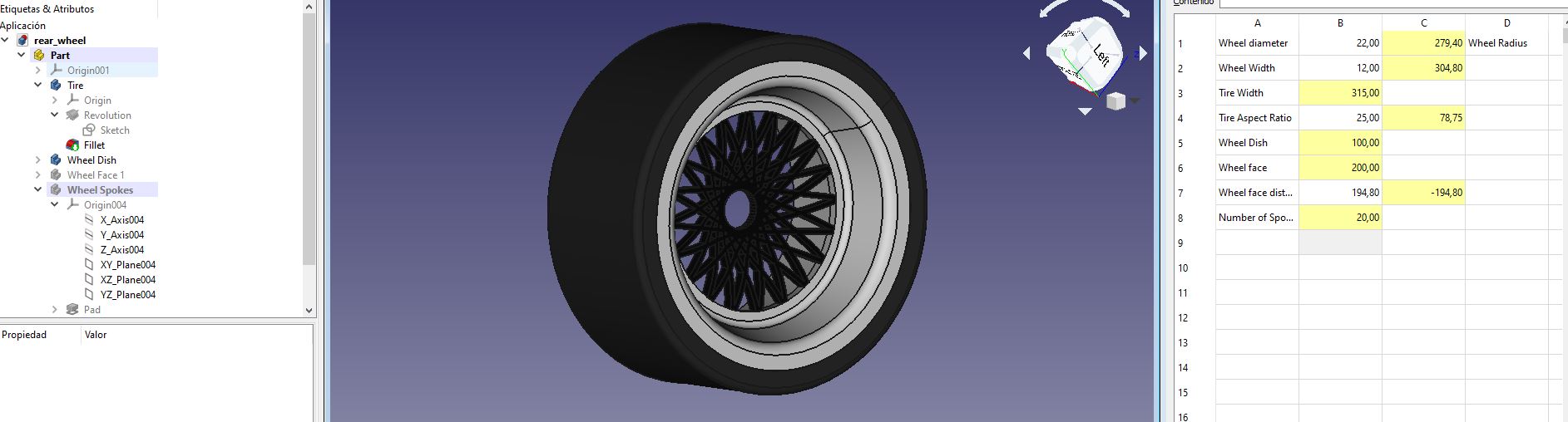
Once I spent more and more time with it, the more confident I was feeling. FreeCAD has a very useful feature: the parameters and the spreadsheet are, to my liking, much simpler and more direct than CATIA. I absolutely loved that! No more Excel connection. Let's try this. I decided to model a parametric wheel and tire combination, which will be one of the parts that my final project is going to need. So first I decided the parameters: the tire size, the wheel size, the different features of the rim, like the number of spokes. In about 4 hours this is the result I achieved. By the way I used my Windows Game Center to record the screen as you can see in this tutorial and a freely available open-source video editor called handbrake to compress it, and you can do it as well by following this other tutorial.
As you can see, the wheel worked perfectly. No matter how counter intuitive the icons looked to me, the quality control was passed. I could use this software more often! However, sadly for me, I've noticed two red flags for FreeCAD. Number one: I was only able to make chamfers of 45 degrees, which can be inconvenient, but my colleague Mauro told me that he was able to, so I'll blame it on poor interface this time. And now reason number two and why I decided to stop working with it: my favorite rendering software, which is Keyshot (I still have the Keyshot 6 version since I was a student), does not read the FreeCAD file. This means that I can't have FreeCAD designed parts mixed with CATIA designed parts on the same render/assembly. Yeah sure I could save it as an STL (later proved wrong), but then, what would be the point of having it parametric? After this sad news, FreeCAD is, for me, a software that I'll use in the future for fast part creation, but will never be my first choice as long as CATIA exists. Also, Sketchfab did not allow me to upload the .FCStd file, and GrabCAD does not consider the FreeCAD extension as a CAD file, and but let's try to upload it anyway. You can get the wheel file HERE. and you can see how it does work in the video down below:
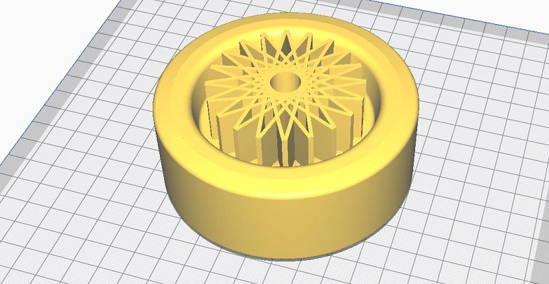
The problem is that I can't generate the correct STL or STEP file. I mean, I the file is generated, but because the center of the wheel with the spokes is actually a boolean operation (intersection), I could not make the the STL or STEP files generate that boolean intersection properly, making the whole program not suitable for what I need. I'm sure it will very useful for simplier parts, but for the geometry I went for, it just does not do the job
You can get the original file for the parametric wheel and tire HERE.
However, as I'm creating a car that has interchangeable parts and every part should contain an RFID or some kind of chip to hold information, here it came my long time lover. CATIA blows away freeCAD with ease, but it's also way more complicated to use and operate, and it has a huge drawback, if you are not a student from a university that has licenses, you will probably don't want to pay 20.000 euros for a CATIA license for a year. Personally? If you are going to get a lot of money from CAD, it's worth every single cent.
The second lover is the best lover
When I started my engineering degree in the university, we started modelling with AutoCAD 3D. I modeled a Bugatti with it! I loved that software, I had so much fun working on that project. Just one month later, I was introduced to CATIA. It was not love at first sight, but now, it's so hard for me to find a software that can even come close...
Catia has a lot of modules. Part design is to design parts, assembly design is to assemble the different parts, Generative Shape Design works with surfaces to give you a little bit more freedom, and then, there's freestyle. As you can see in this YouTube tutorial, Freestyle can let you have a rough model of a car in a day However, my technique is a bit different, as I have no blueprints...
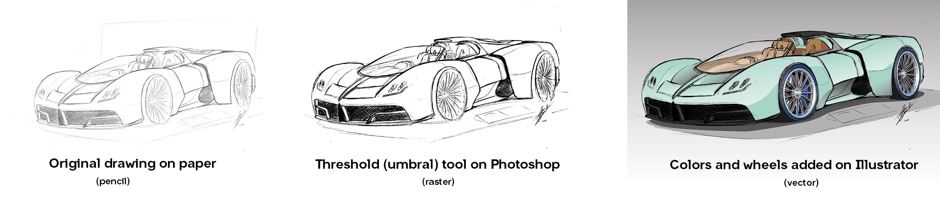
As I always like to do, I started to design a car model by hand. My inspiration was an old drawing that I used to introduce myself to Oscar Scaglietti and his son Matteo, while I was living in Italy, in 2018. Oscar was for me a childhood hero that I had the opportunity to meet in life, and I'm very grateful for everything he taught me about car design and engineering during our chats. So this is a hommage for me. Grazie mille, maestro.
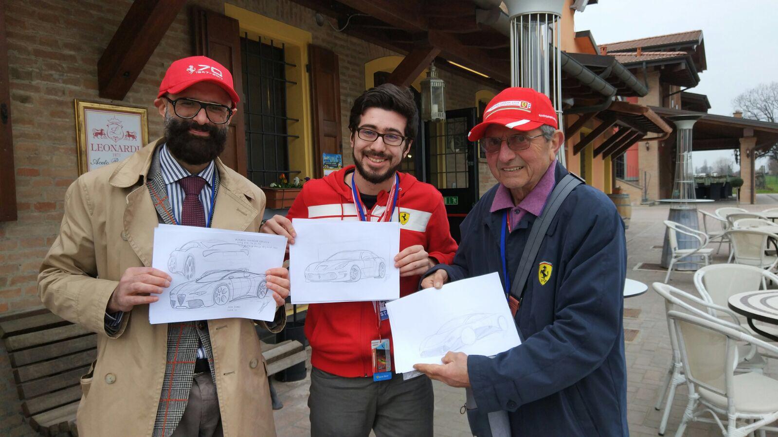
However, Matteo kept those designs in his office, so I decided to re-draw them. Again, I still don't have the blueprints of the car, just some hand-drawn designs that I need to convert to CATIA. So, even if I like to document to tell my story, I'm going to give a couple of tips here on how to design a car in CATIA with no blueprints.
my CATIA car body design methodology
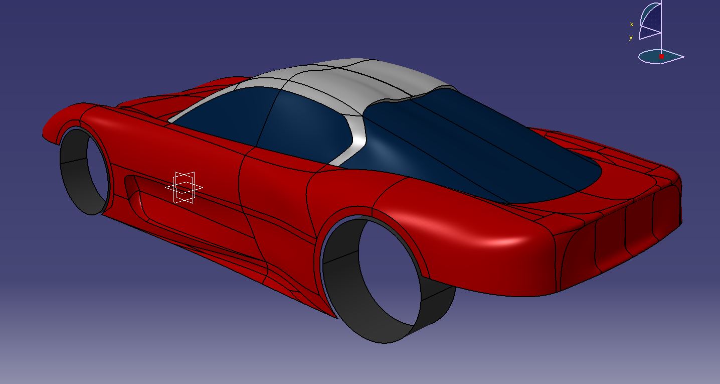
Keep in mind that here we are going to 3D model a car in a very rough shape. No class A surfaces will be made and we may have some slightly ugly surfaces, but the result is 3D printable and you can add some putty and sand paper after to smooth the surfaces out. Also, as I was going to have the interchangeable parts, I only designed the part that was going to stay: the body. The front bumper, the rear bumper and the wheels are removable, so I was initially planning to model them in other softwares (I may try to use rhino later, but for now I'll stick to my loyal lover). So here I'll show you how I modeled just the body, with no bumpers or wheels.
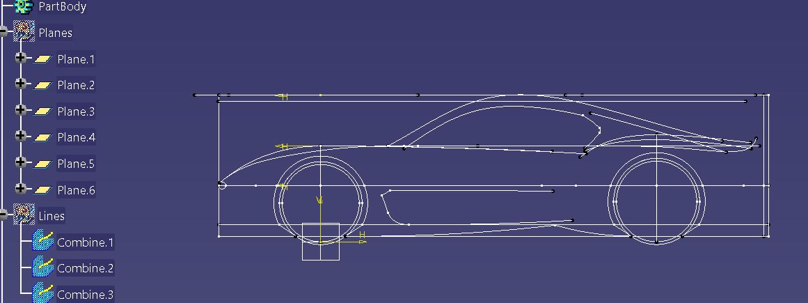
Start in the Generative Shape Design with a very ordered array of geometrical sets. Planes, sketches, lines and points should be always separated. Right click on the geometrical set and "define in work object" everytime you're going to add a specific feature. Once you've done that, you can start, with very basic sketches, to define the main lines of the car. Have them properly annotated, as if you change one of those lines in the future,that change should propagate through the rest of the design.
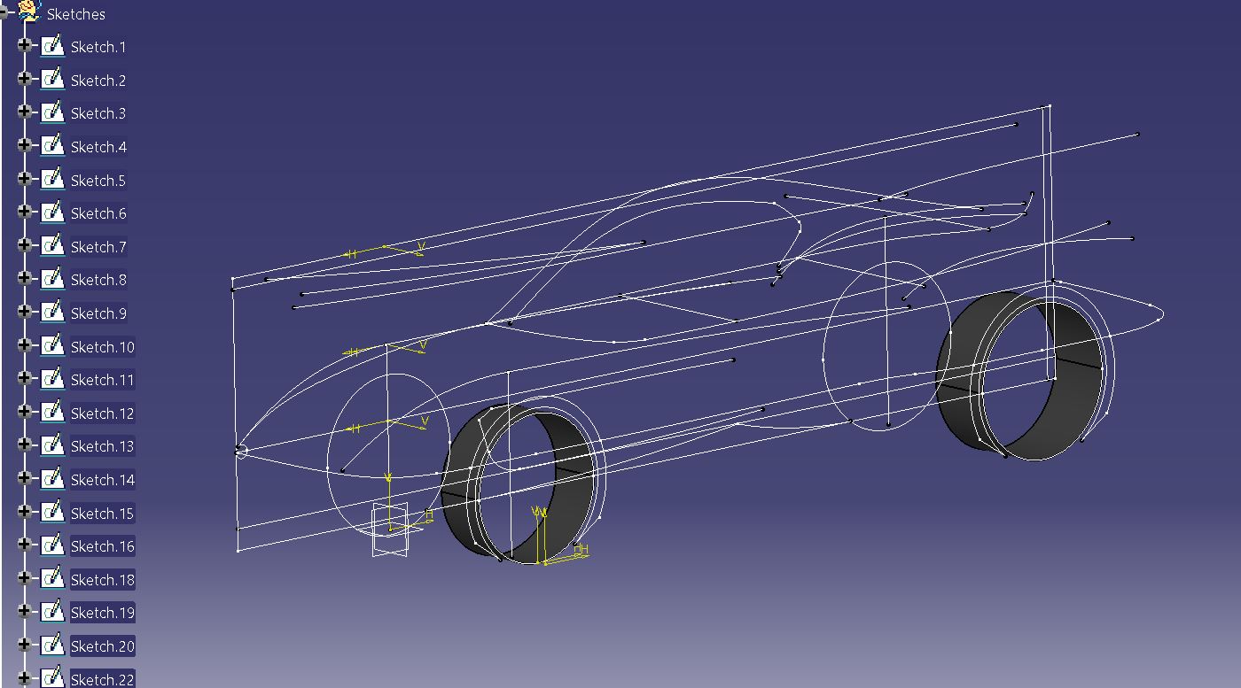
Once you've finished the basic sketch, make it three dimensional! This is done with commands like "combine". You can also extrude some surfaces like the wheels so you can actually have your pile of lines reminding you that you're designing a car.
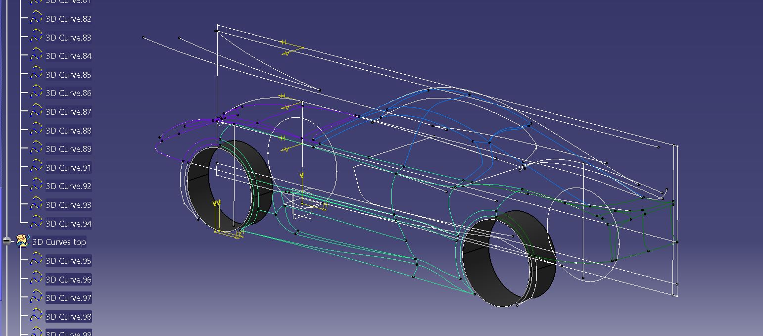
Now switch to Free Style. Free Style is the CATIA module that allows you to play with 3D lines controlled by nurbs, that are control points that define the line. the line.
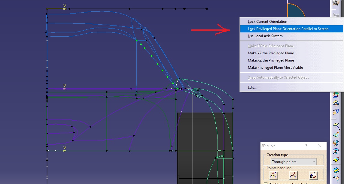
It's super important that when you're working on the nurbs you are looking at your model from one of the isometric views and have the Lock privileged plane orientation parallel to screen activated by right click on the axis system and selecting it as it's shown above. This will make that when you move the nurbs, you will only move them in the bidimensional plane that contains them. This 3D Curves should be interconected, placing the nurbs of the new lines on top of the old ones, which makes the model self referenced. When you move a line, the rest of the lines also change.
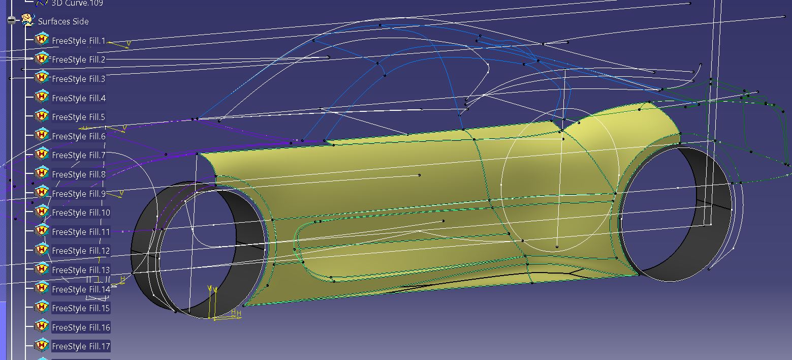
Now the magic happens. Use the command FreeStyle fill to create a surface that will be forever linked to the 3D curves that define it. If you modify the 3D curve by adjusting the position of the nurbs, the shape of the entire surface will be changed. It may take a while to get used to this technique, but once you learn how to move the nurbs, you will improve your workflow in no time.
On this video you can see how by moving one nurb on one 3D curve you can change all the surfaces related to that particular 3D curve. This is extremely useful to refine the surfaces or to modify the design, as it's not usually this easy to control the shapes of complex surfaces in other softwares
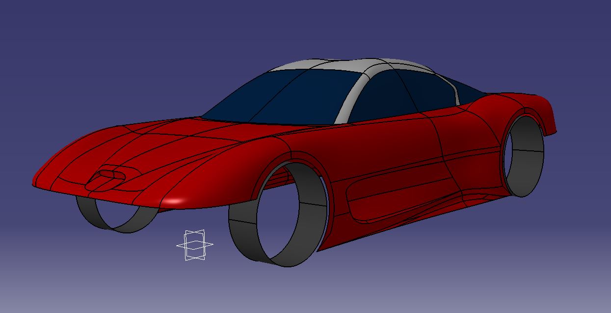
I'll soon redesign the bumpers and the underbody of the car in order to make it 3D printable, but for now, this is the final result for the week.
As the STLs for every singke part are too big for them to fit in the repo (almost all of them are over 20 Mb), I'm storing them in my skecthfab account
I hope you enjoyed this process as much as I have, and see you next week!