3D Scanning and Printing
week 5 Group assignment is to test the design rules for your 3D printer
3D Printing
3D printing is an additive manufacturing technology which recently get world's attention.For the past 10 years 3D printing grew a lot because of the open hardware world.so,this is an additive type manufacturing method which is done by adding materials technique.for prototyping and product development designing the 3D printing is very helpful we can almost print anything even complex structures,real homes etc...
there are many type of 3D printing technologies available.Each invented for different different purposes.There is a printer available to print bio organs also another printers available to build working rocket engine's nozzles ,nowadays people are using the technology to perform beyond our imagination
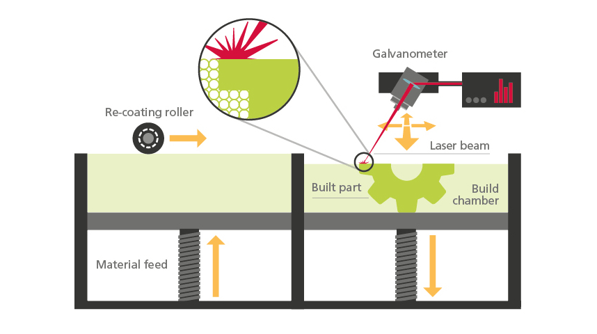
Selective Laser Synthesis(SLS)
This type of 3D printing technology uses for industrial purpose.It use a laser beam to fuse powdered material practical selectively . The materials are mostly high melting temperature plastics like nylon and some metals.so a roller fill the powder in the bed cavity layer layer . See the picture below
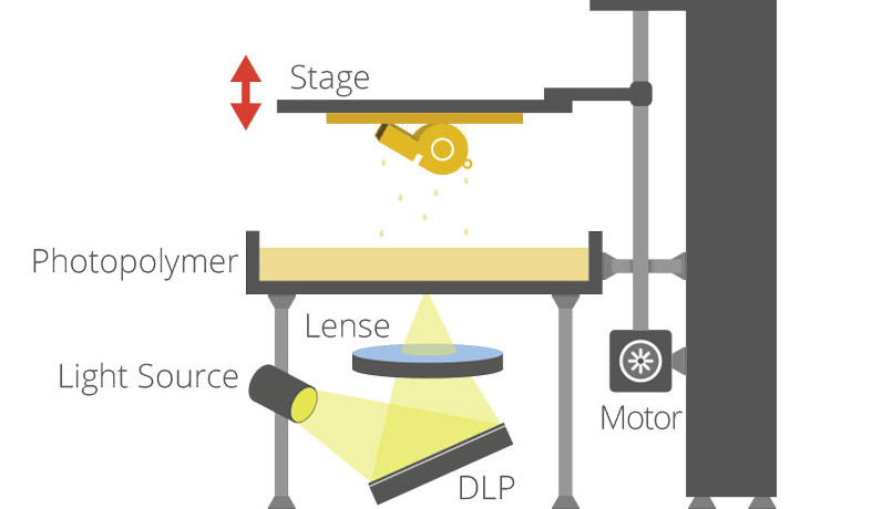
Stereolithography Apparatus(SLA/DLP)
SLA and DLP technologies have similar working method,each doing with a photo curable liquid resin as the printing material.They use UV light or UV laser for cure the practicals together.A selective mechanism or a dlp projector is helps to point the laser or uv light to job layer by layer so the projection come from under the resin tray and the print bed/head moves up(z axis) from the resin tray
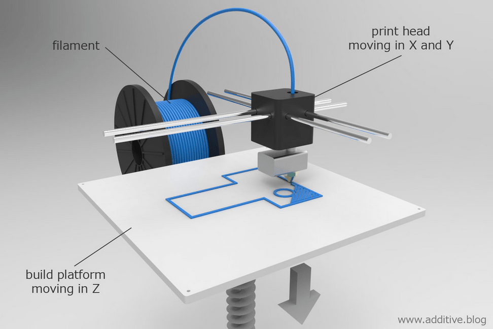
Fused Deposition Method(FDM) or Fused Filament Fabrication(FFF)
these are the cheapest 3D printing technology available to use like a plug and play device.like in the picture shown,it used a material reel fed by a controlled motor through a heated nozzle head which is controlled by two motors alongside x,y axis,so which can plot layers with respect to the moving z height controlled by another motor
Ultimaker 2+ FDM 3D printer
So fab lab kochi has ultimaker 2+,It's a cartesian type FDM 3D printer for Fab academy
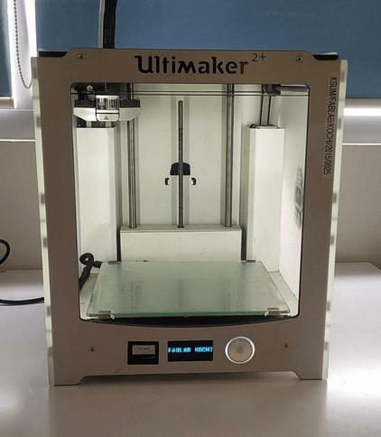
Ultimaker is one of the world biggest commercial 3d printer manufacturer with strong open source communities.The also makes the slicer software Program called Cura which is open source and free for all .
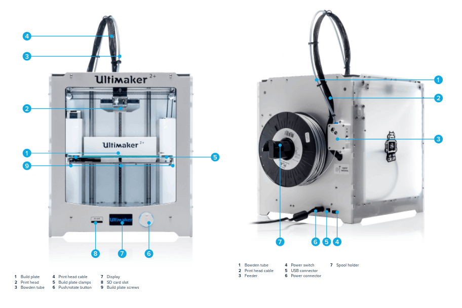
The above figure from Ultimaker 2+'s Guide shows the important body parts of the Ultimaker 2+ for using . For more click here to see the guide.
STL Slicer
3D printers are basically called CNC machines and it can only perform what we instruct to do in the form of G-codes. So in order to create G-code from a 3D file we use a software program called Slicer Program. there are many type of slicer programs available like Cura,simplify3D,Prusa slic3r,Slic3r etc...
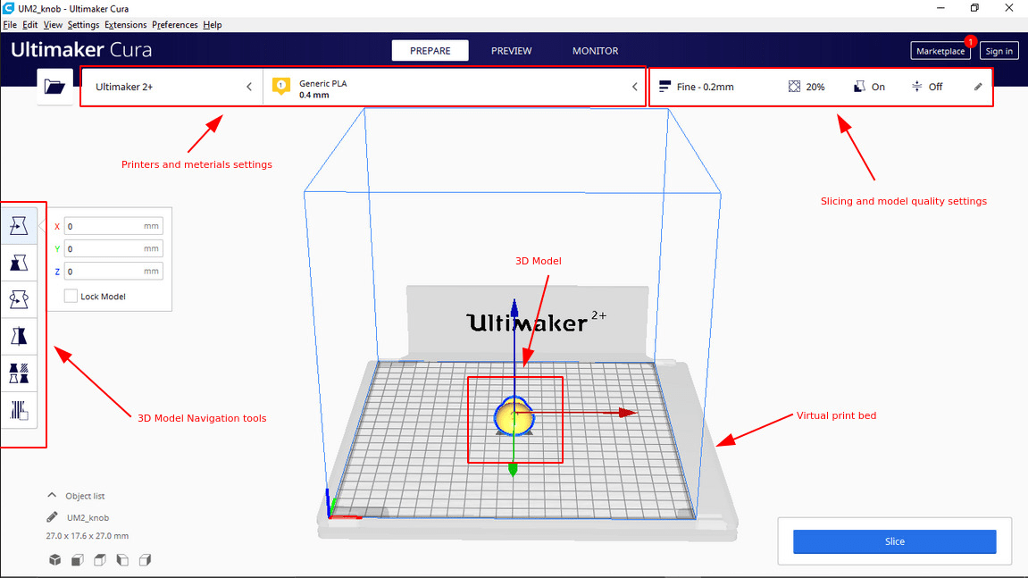
Ultimaker Cura is one of the best user friendly slicer tool which is open source and free to use. We don't want to set anything special to use the software because we are using the 3D printer also from ultimaker. So, just select the company ,printer model number and go and slice. For more refer this Tutorial from ultimaker.com
Test Print : Checking Design rules
In-Order to learn How to 3D print and knowing the machine limits,print tolerance or The design rules we have to print a test print which help us measure and find them.
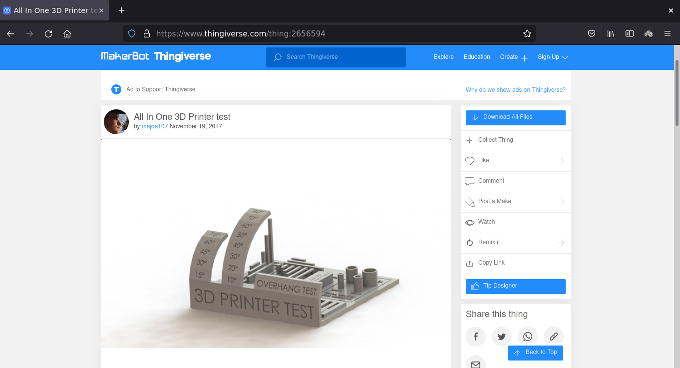
So we found a free '3D printer Test' File from Thingiverse.com which can be use full to know all the tolerance like over hang ,shrinking x,y tolerance tower printing and bridge printing etc... Thingiverse is a website where we can get free and open source 3D printable files or Awesome projects .
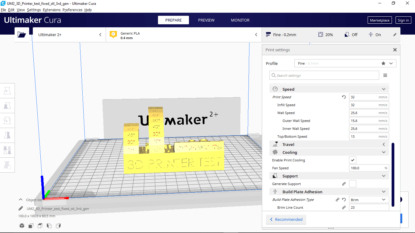
We downloaded the file from Thingiverse and loaded in Ultimaker cura then applied then Print setting without any support in 0.2 mm layer height and 20 % inner infill.
Layer height is the one which results the surface finish quality of the print it can be vary from 0.06 to 0.3 that depends the printer and it's hardware precision.
Infill is defined how much inside fill needs to make the print wright less or rigid while printing this infill print quality can be adjust from 0 to 100 % .There are various types of Infill pattern structure available for making the print structure more mechanical properties.
Coolingis a feature that helps to cool the printed part immediately after the print material came out from the nozzle which can be helpful while printing angled objects,bridges..etc.. .It is possible to adjust the fan speed from 1 - 100% depending on the print material cooling time we leaving it as 100% default for PLA.
Supportis used for printing horizontal or angled object in mid air without touch ing the print bed .So the Printer will do thin wall pattern as a support structure beneath the model or part to be printed .The support can be removed by hand or with helps of some tools like knife,nose pliers ..etc..
Build Plate Adhesion.If the print is too small it wont be stick to the bed till the printing or the print bed finish Isn't that good ,In those case this feature can help us to give a Adhesion options like a 'Brim' of a tree which hold the print part without falling of the bed while printing. We selected 'Brim' for this print which is totally unnecessary for this model.
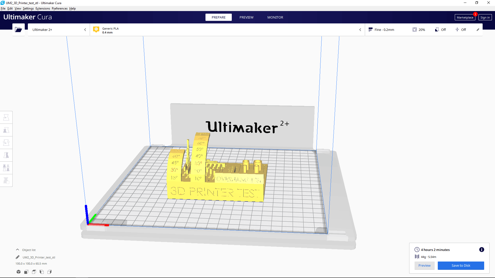
In the bottom corner it shows the time taken and material consumption after we clicked the slice button. If we click the preview shows a simulation of the 3d print layers by layer.
The above video shows how the preview looks like. It's possible to play a layer print head path to see how the print is gonna be.
before start printing we have to make sure the pinter's bed is leveled .so there is an printer settings to check the print bed is leveled or not.If the bed isn't leveled we can set the level using the bed adjust knobs and the rotary encoder of the printer.
The above video from Saxion FabLab Enschede youtube channel explains the whole Procedure of the Bed leveling in Ultimaker 2 3D printer
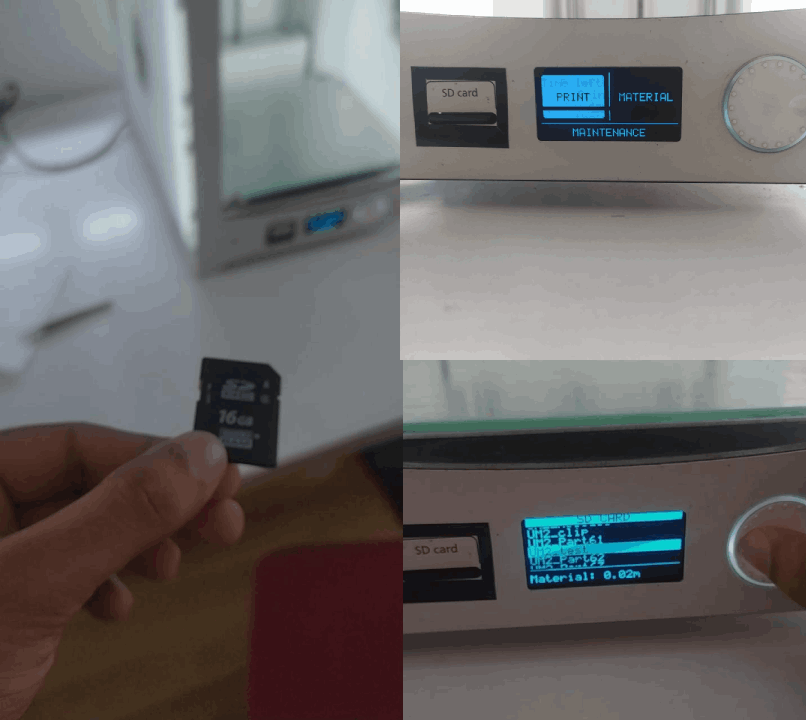
Then we saved The sliced G-code out put from cura software to a SD Card then inserted to the printer and selected Print options that shows the files saved to print.just hit the file name and confirmed to start.
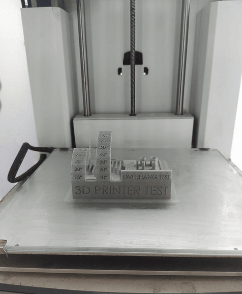
After a long 4 - 5 hour the print is finally completed and ready to take out from the Print bed.
Then we de-attached the glass bed from the printer and removed the printed Object by using a Edge scraper .It is important to make sure the bed is not in temperature while we take out from the printer.
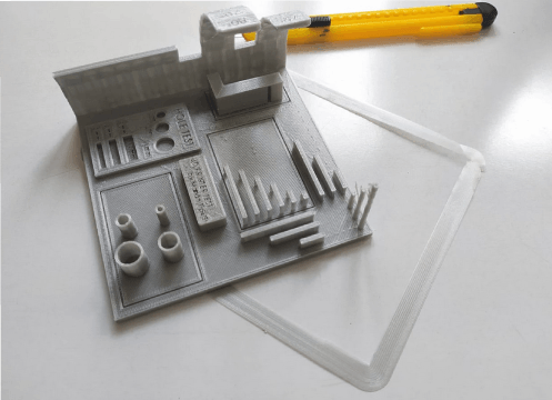
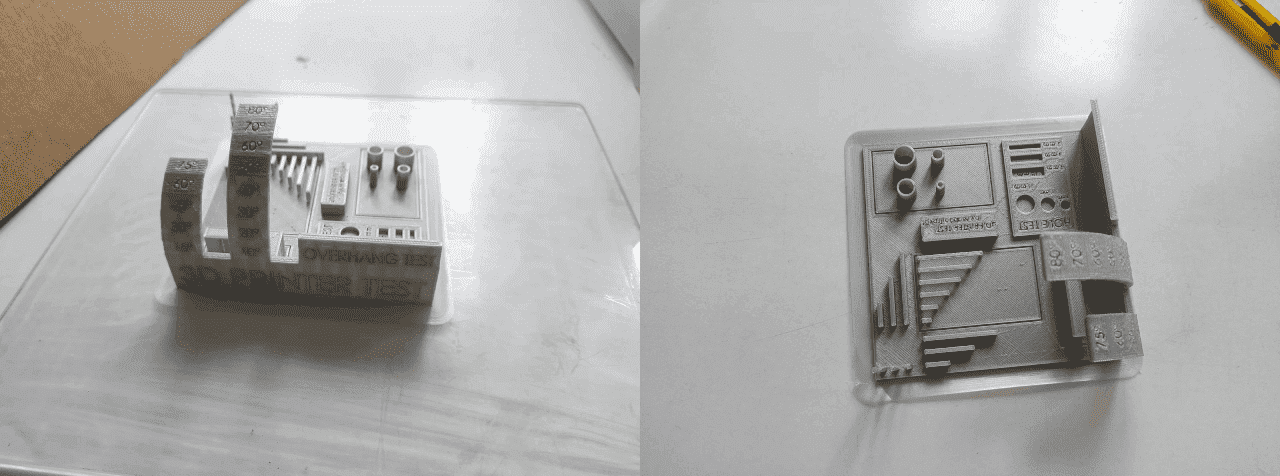
We cuts out the brim layer from the model using a pen knife. then we started to measure and inspect The printed object to understanding the print tolerance
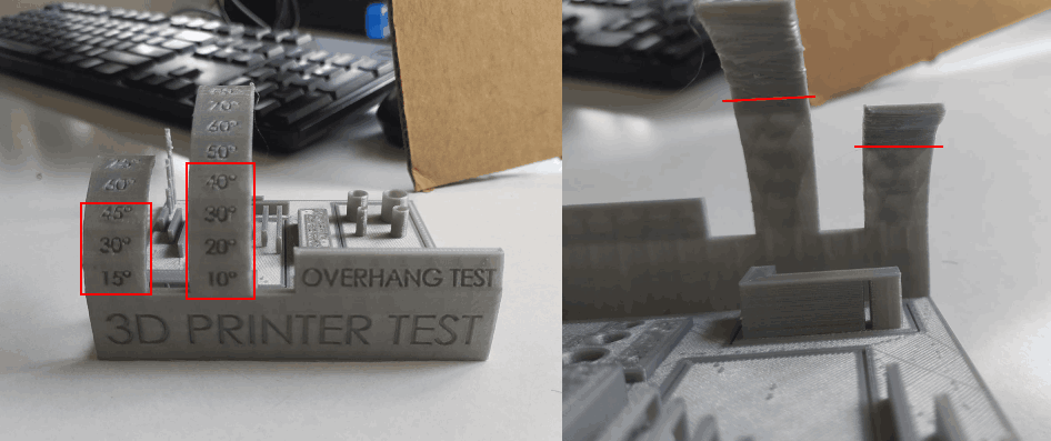
In the Over-hang print results Indicates that it's ok to print upto 45-50 degree angles without any supports and it's also possible to print upto 80 degree but may loose some features or will get a unfinished bottom(area under the angle). 45 is the best.
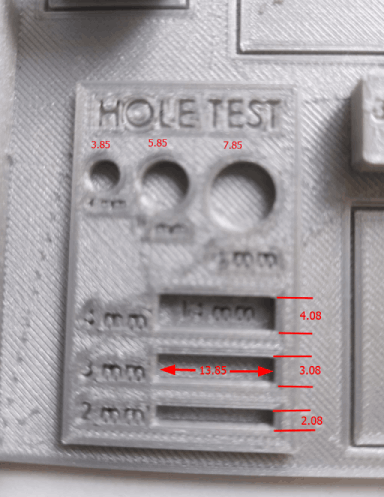
In the hole test we get a tiny error of 0.1 -0.15 along Y axis and 0.8 along X axis The differences we measured is given in the above picture.The machine is almost precise as 0.5 - 0.1 mm from the study
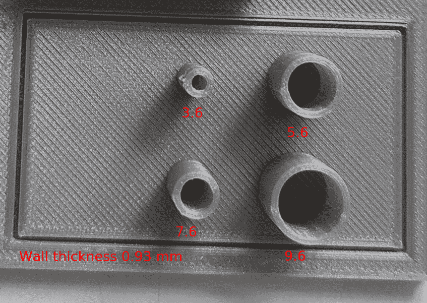
From the cylinder we got up to 0.4 mm differences from the actual dimension. It is probably happened because of the shrinkage of the material.
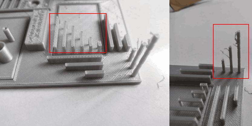
The bridges are printed without anu under support and just using the material cooling technique a Part cooling fan helps the printed material to cool immediately and as follows the bridges are possible without a nice finish It's better to avoid because it's not gonna same in other materials like ABS but PLA it's Ok with the part cooling fan . Also the tower printing was failed at a certain height and That's not a good Idea to print a small diameter tower like a shaft in a 3D printer
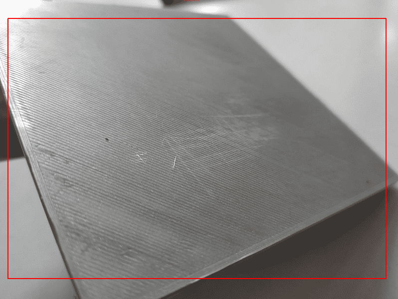
The bottom finish was came out like a glass finished surface because the print bed is made out of glass (Borosilicate glass may be). That's kind of cool for flat surfaces.This also depends each printer's bed technology
Our Observations are :-
- Overhang: Over hang of draft angle 45 degrees could be printed without support
- Bridge width of 25mm is possible without support and 100% cooling
- Max height for 2mm x 2mm column is 12mm
- For cylindrical holes: deviation in diameter=0.12
- For rectangular holes: X-deviation=0.08mm, Y-deviation=-0.15mm
- For thin extruded cylinders: deviation in thickness=0.2mm deviation in outer diameter=0.22mm
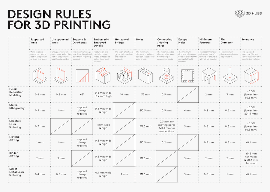
For more this Design rules table from hubs.com will helpful also refer this Tips and Tricks from The university of melbourne
week 5 assignment is to design and 3D print an object (small, few cm3, limited by printer time) that could not be made subtractively , 3D scan an object (and optionally print it)
Making a Design
so the assignment was to create something that could not be made subtractively.So I decided to make a flexible 3d chain structure which uses in today's 3d printing wearable technologies.I created an hexagonal shape in fusion 360 and extruded its each 3 intermittent sides in different z level .Then I duplicated the body and made a hexagonal chain also made sure its not touching each other
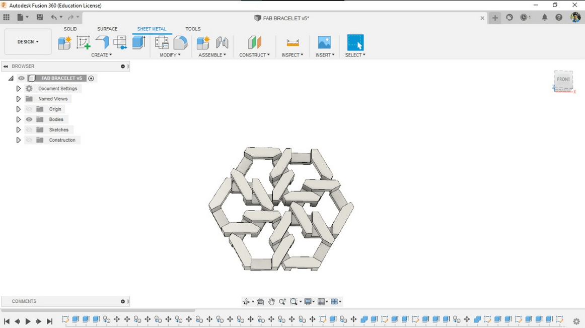
then I did a test print to check it works or not
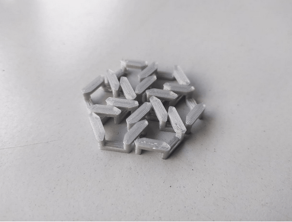
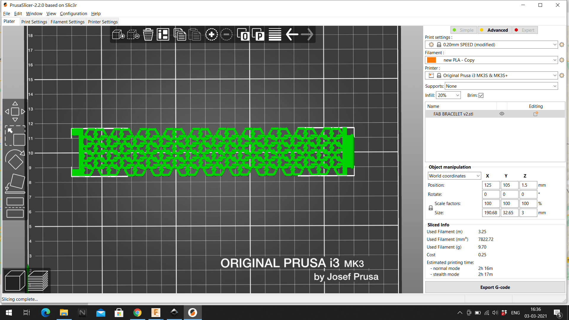
The printing was successful .so,I planned to make a bracelet with the design and copied multiple bodies and arranged in a bracelet shape dimensions are 160x30 mm approx.Additionally also added a joint to strap the bracelet on hand
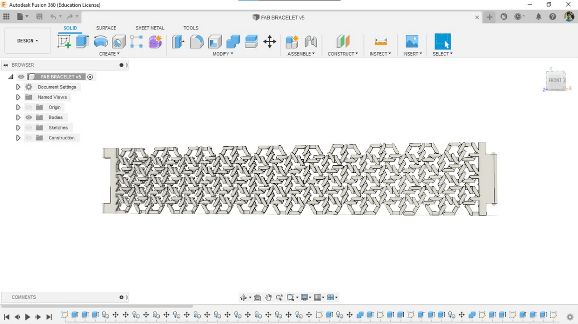
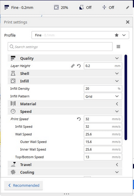
I converted the file to stl file by right clicking on the project directory then loaded into Ultimaker cura .Then sliced in 0.2 with 20% infill.
see my design that I attached here
Slicing in Ultimaker cura
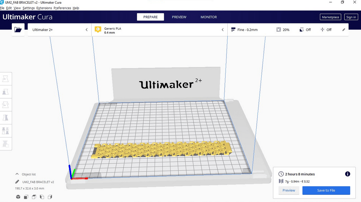
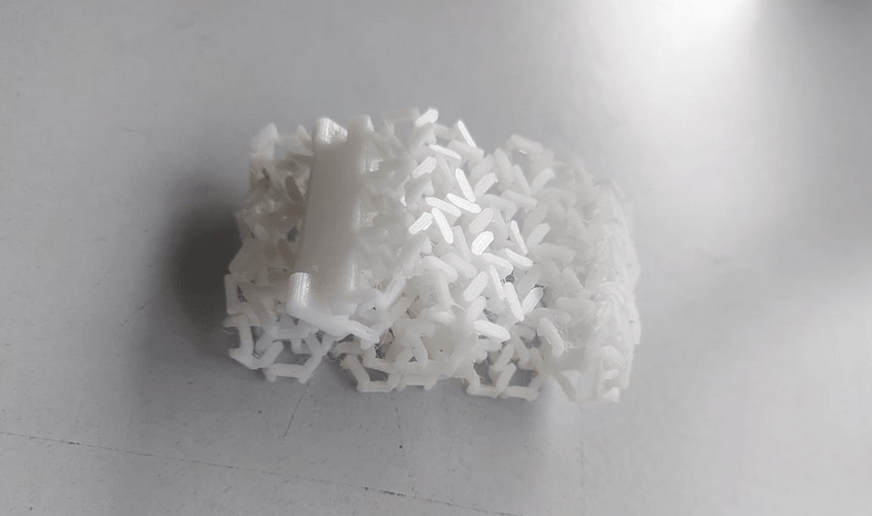
Then I put print in the ultimaker 2+ fablab printer,but It seems there is sticking problem of first layer in the ultimaker 2+
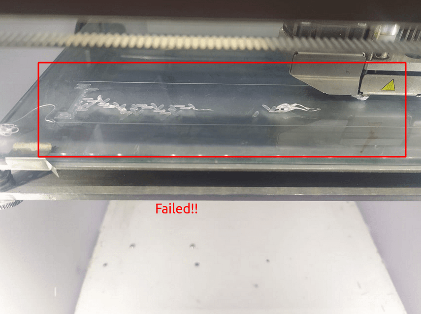
I Aborted the printing job then tried to reduce the printing speed several time also tried to level the bed
but still not getting successful first layer.
In Prusa I3 MK3
I have 3d printers in my home but they have good printing surface with PEI sheet so I understands its problem with the bed sticking because the ultimaker 2+ have the glass bed .but,i'm in superfablab kochi so we have other printers like prusa i3 so I sliced it for prusa i3 with prusa Slic3r software and put print in Prusa i3 Mk3 printer.
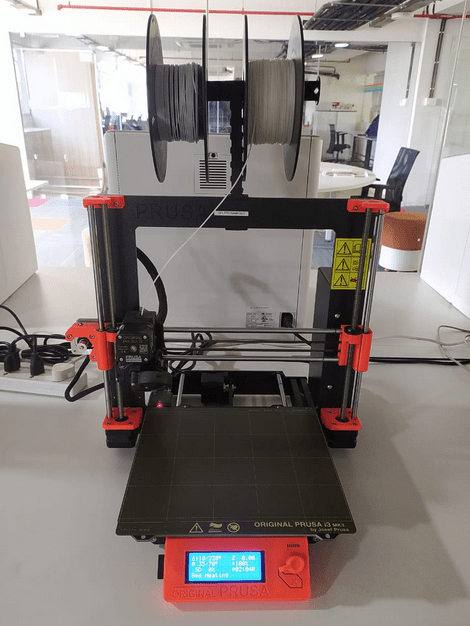
The prusa i3 MK3 is one of the advanced cheap and best printer which don't have coast like ultimaker.I have cloned printer of prusa model.Prusa has several features like removable magnetic PEI coated bed ,Auto bed leveling and etc... .And its very silent.prusa uses different STD Filament ,diameter of 1.75
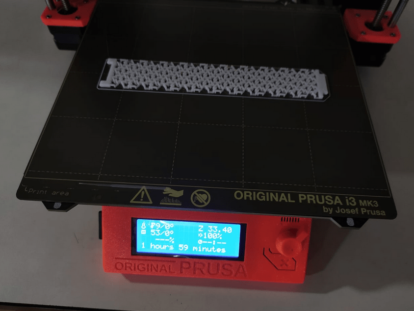
Prusa slicer is great just insert and select profile and print thats it .after saving the file to a SD card inserted that in the prusa machine then it started to auto bed leveling its self.after leveling it starts to print.I got successful first layer!!
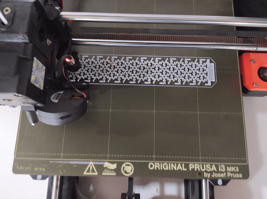
After 2 hour the print completed,Then I removed prusa bed and taken out the bracelet
The taking part was way better than in prusa than other printer.just flex and take the printed part out,is that simple
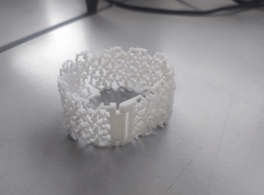
Awesome.This was new for me to design something like this,I only know about Mechanical designing.It can compress it like a chain watch
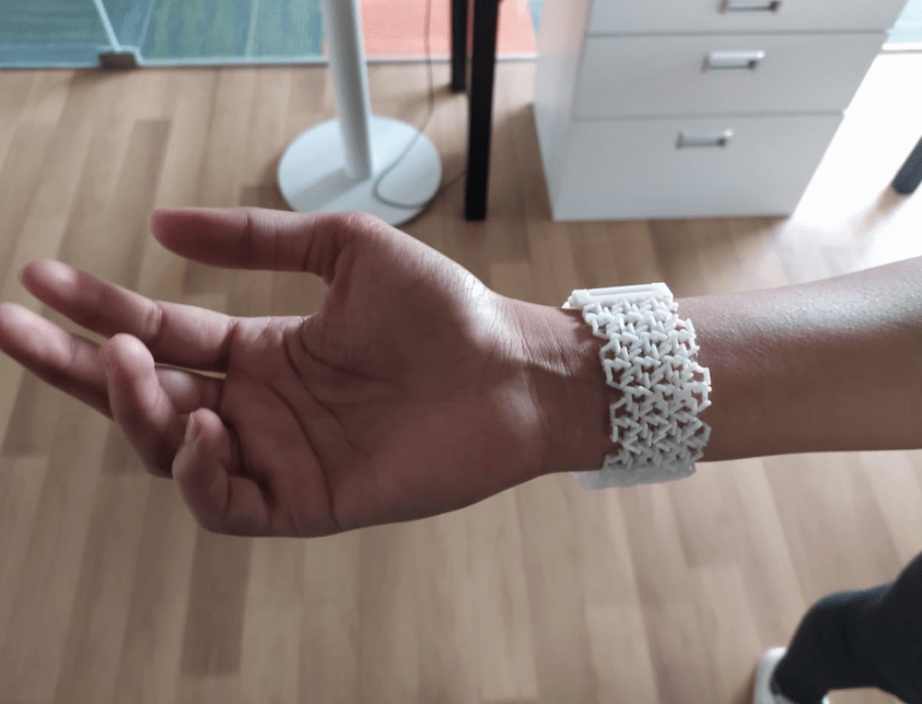
The strap joint is working fine .I let my friend wear it
3D Scanning
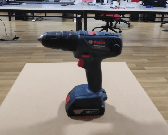
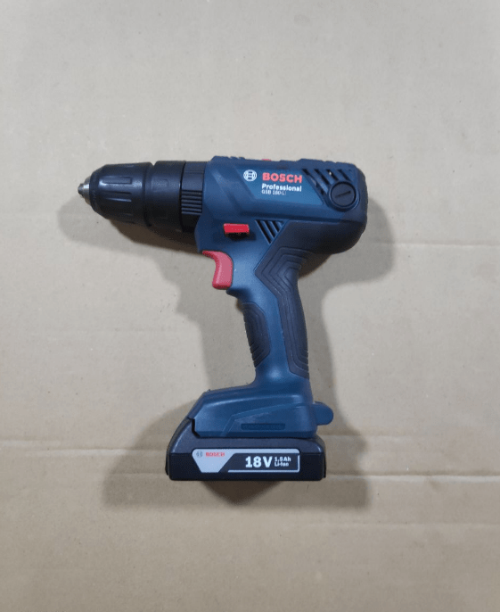
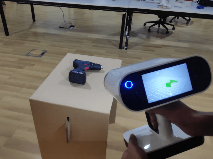
I placed the object on a desk for scanning it is necessary to have a nice flat surface around the scanning object.
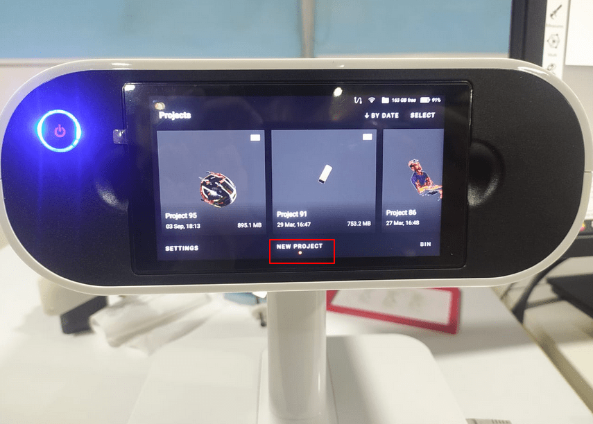
The Artek leo turned on with a single press of button on the Leo and then started a new project by clicking 'new project' on screen.
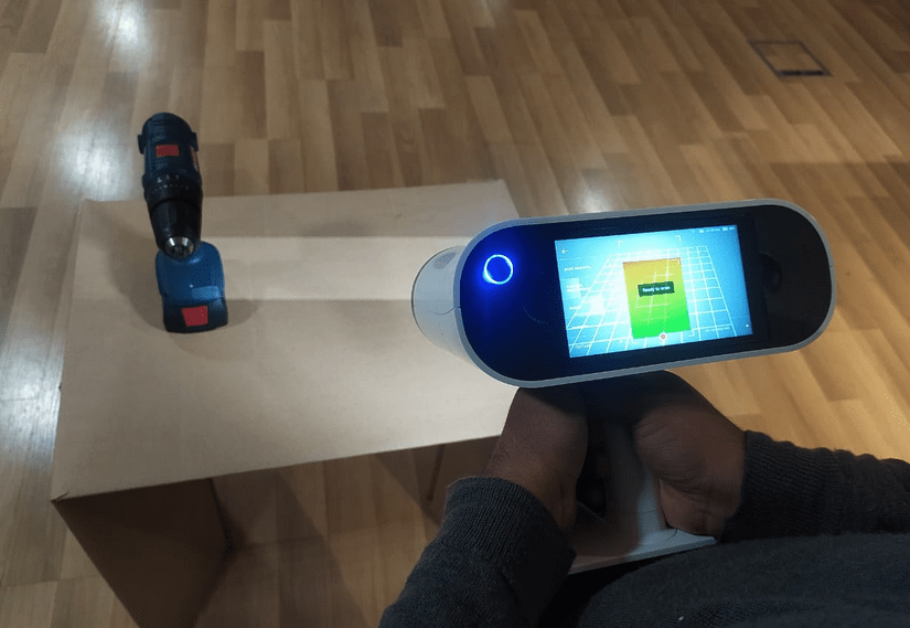
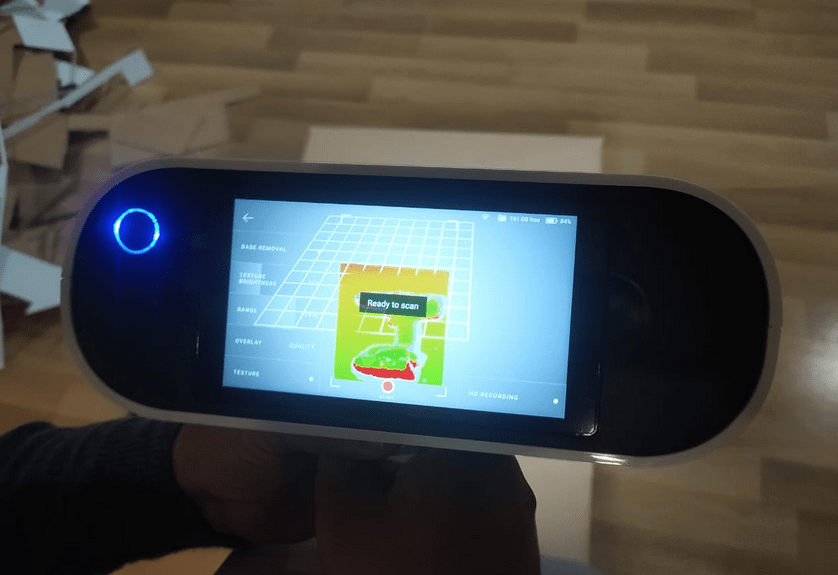
Then I pointed at the desk to as the machine instructed and it says 'Ready to Scan' then the message disappeared for scanning window.
I kept pressing the trigger button on the leo's handle to start and continue the scan.The data slowly started to pop up in the screen as I move around the object.
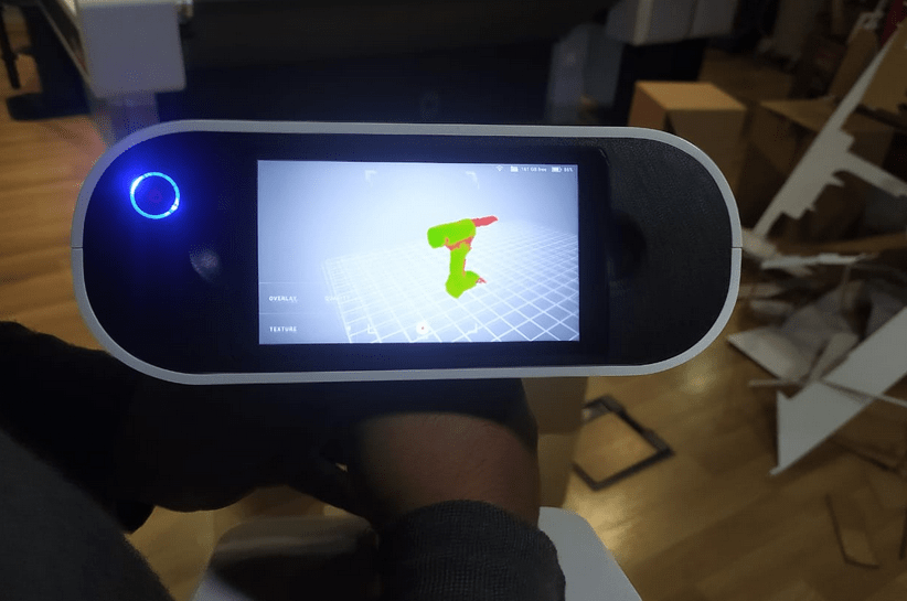
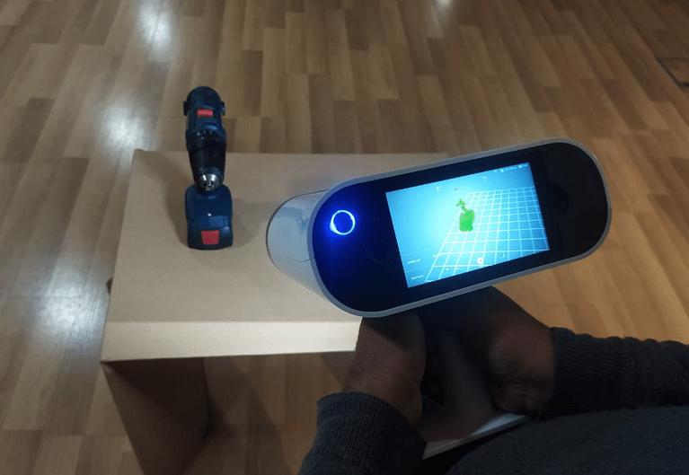
While scanning process the uncovered areas shows in read color or red dots and covered will show green and also if we point too close it will turn to yellow and if it is too far it will shows blue color , keeping in green is the best distance for scanning.
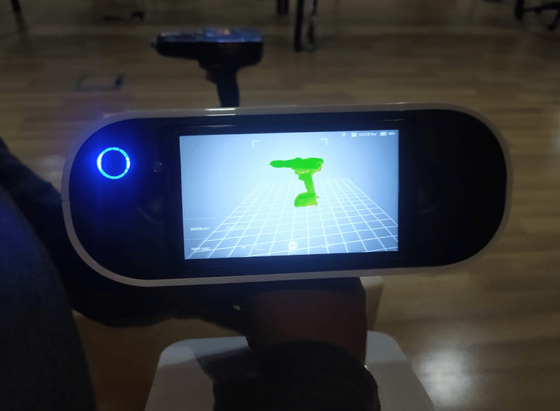
So,I almost scanned everything in this position so it will be better if I can scan details of other sides and bottom as well.
For capturing the bottom I lay down the object on the desk like the figure and then continued my scan.
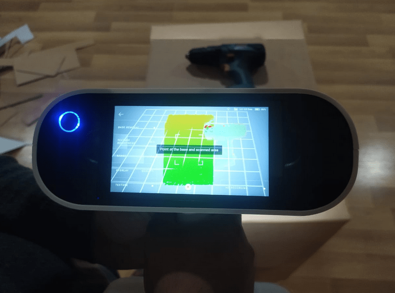
So while continue the scan on the same file a message instructions says to 'Point at the base and scanned area'.It is searching for areas that it already know.
After I shows the scanned area it shows that 'Ready to scan' and started to scan.Then I scanned the complete side including the bottom.
Then I flipped other side of the object and continues the scan completely upto the bottom of the object.
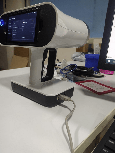
After all the scanning done I connected the Artek Leo to the Desktop PC using an Ethernet or LAN cable.
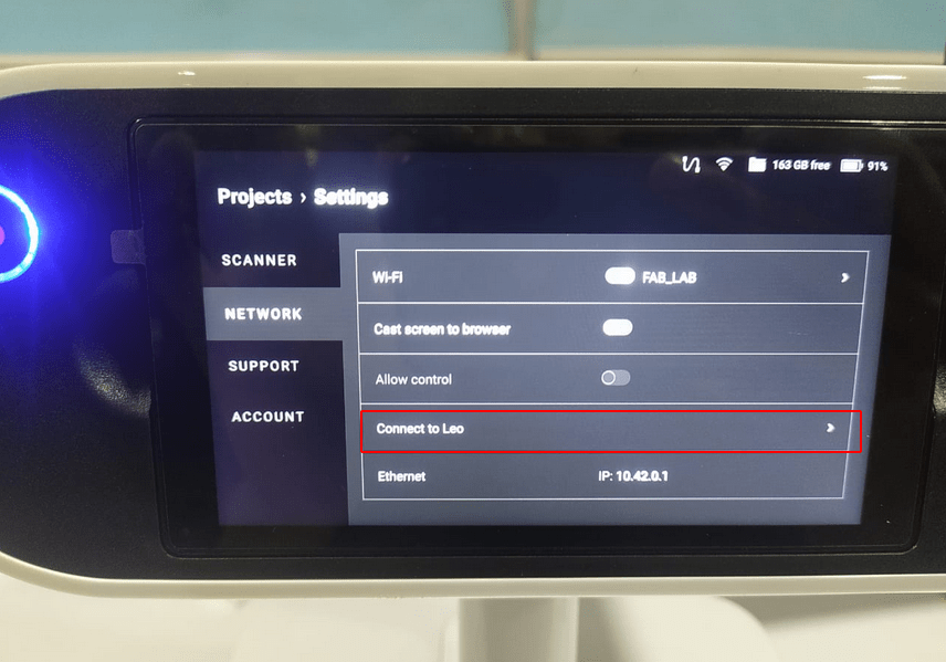
Then opened settings in Artek leo LCD panel and switched the tab to network section and selected the 'Connect to Leo' Option.
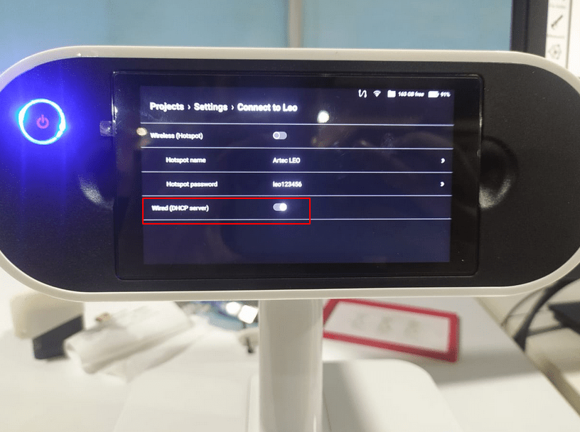
Then turn on the DHCP server for creating a server connection from the leo to the PC. It is also possible to use other ways like using wifi networks and wifi hot spot. But our Lab's Desktop hardware doesn't have any strong wifi adapter in it.
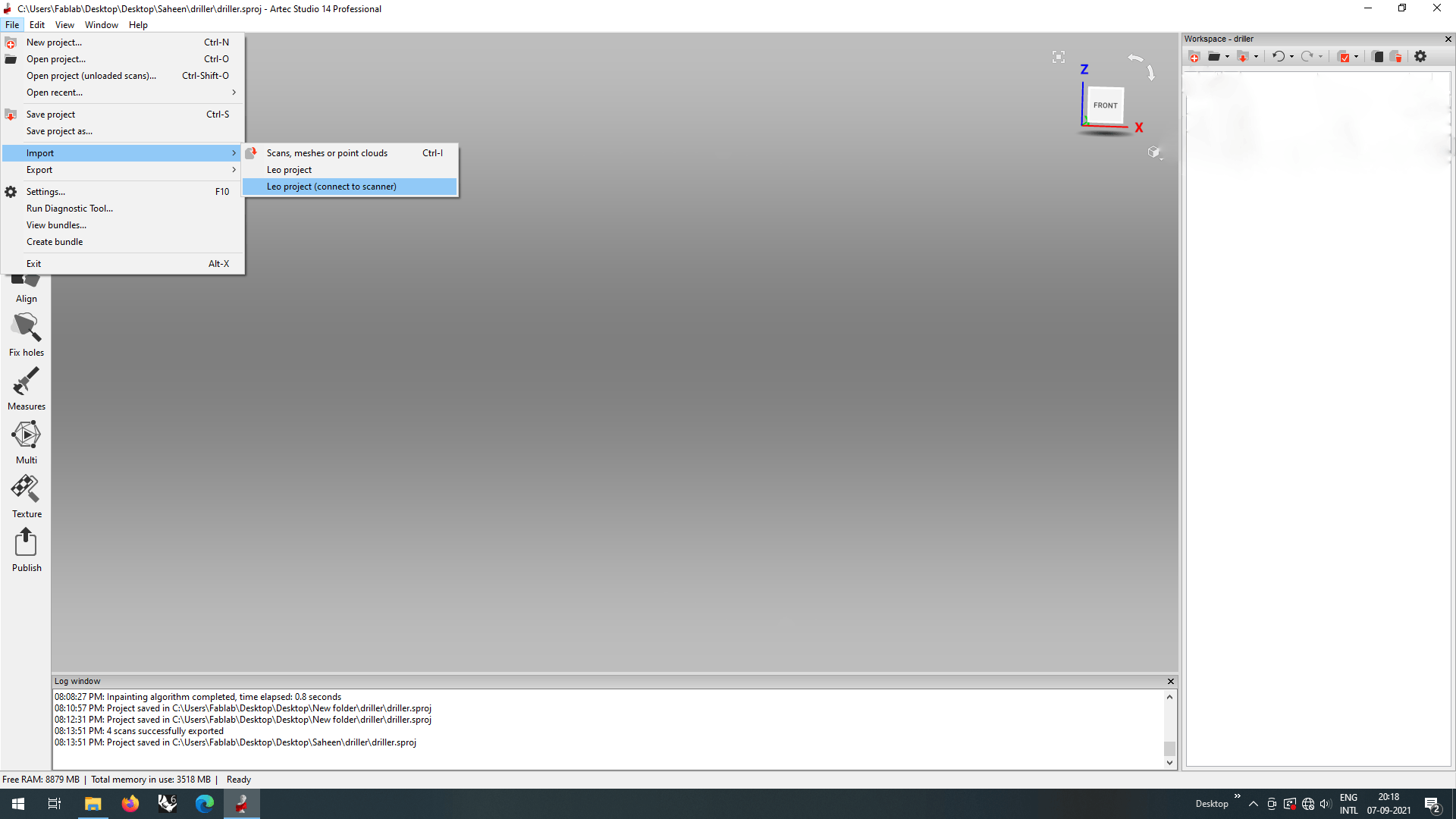
And I opened the Artek Studion then Clicked 'FIle >> Import >> Leo Project(connect to Scanner)' for importing the scanned files from the Leo scanner.
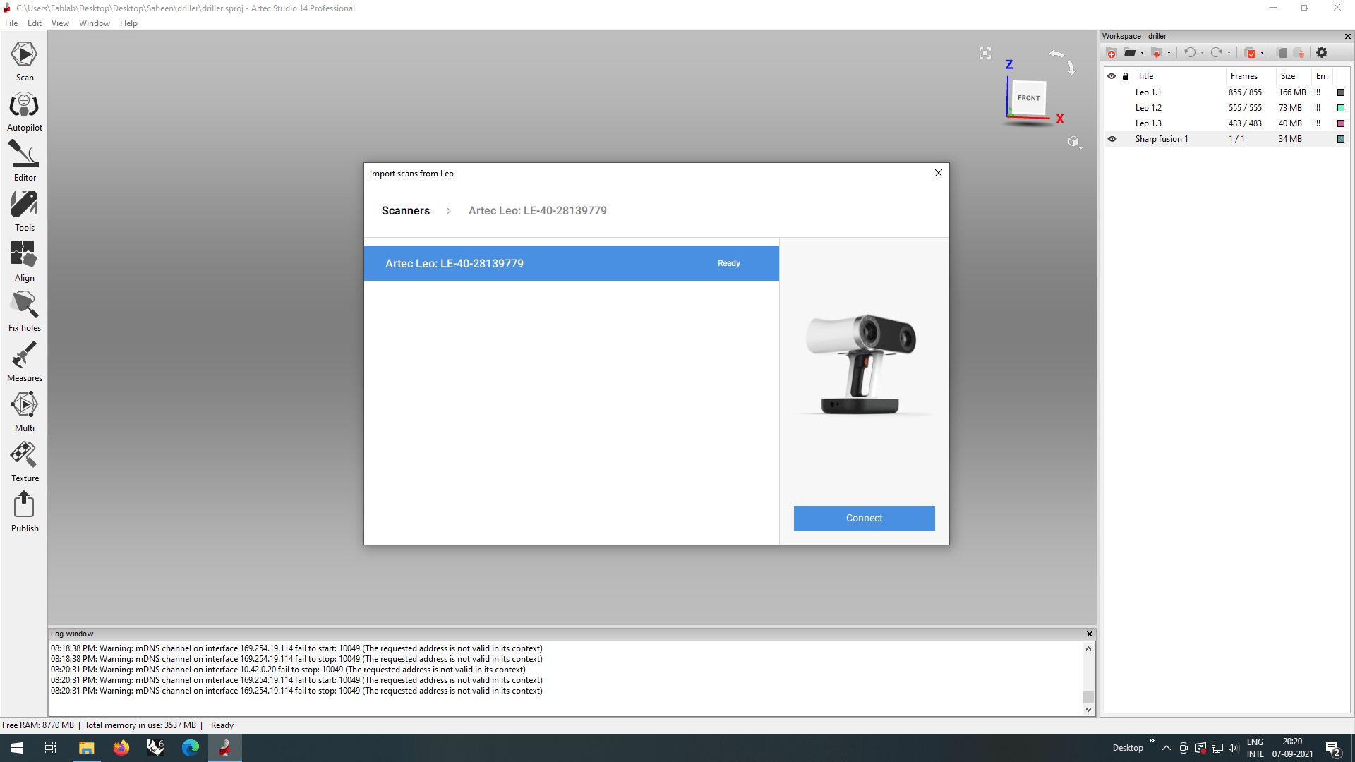
Then in the following window I selected the scanner That appeared in the searching list and clicked 'connect'.
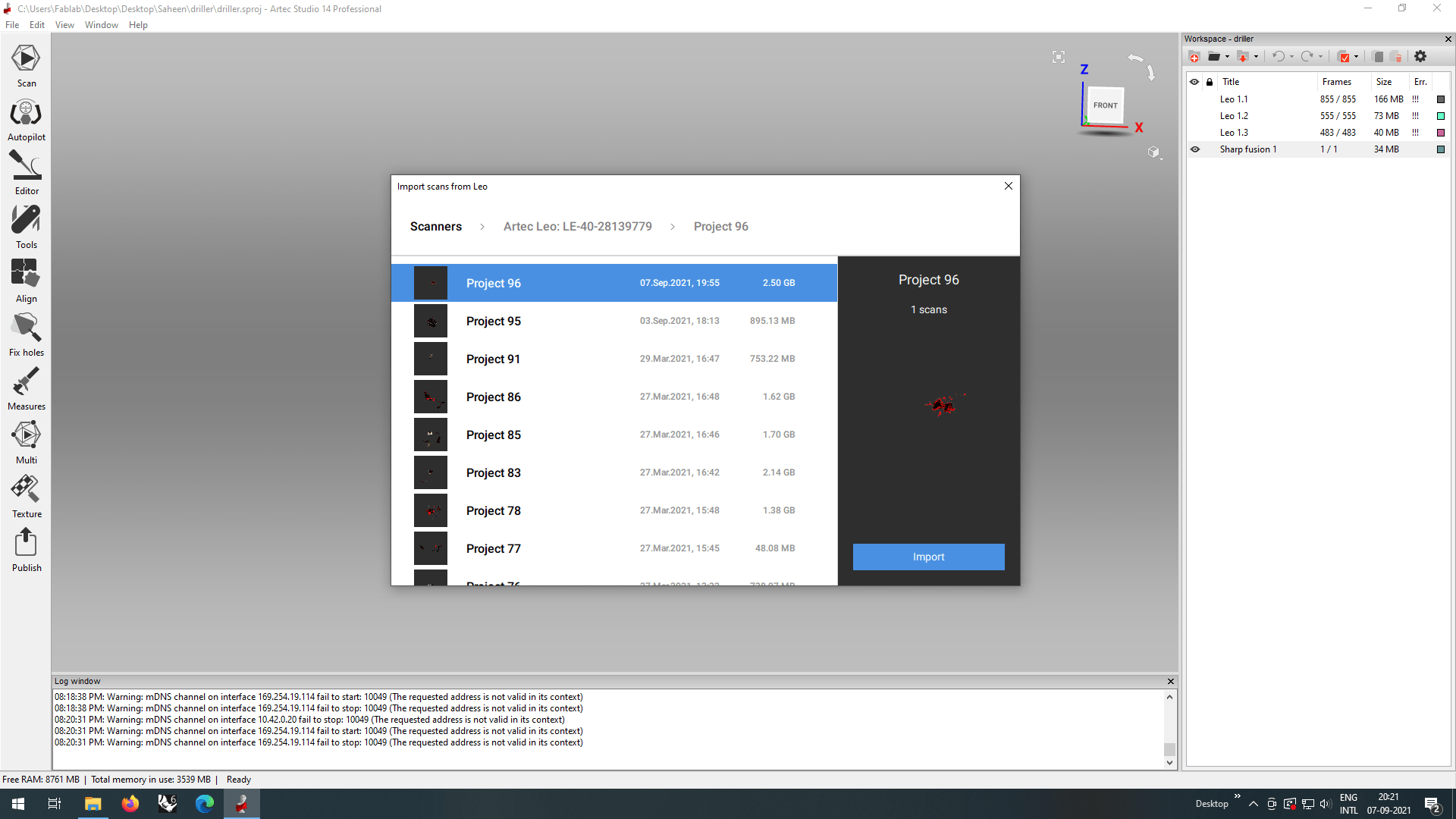
And then it shows the Projects scanned by the Leo scanner ,I chose the project scanned by me to import and then clicked the 'Import' button.
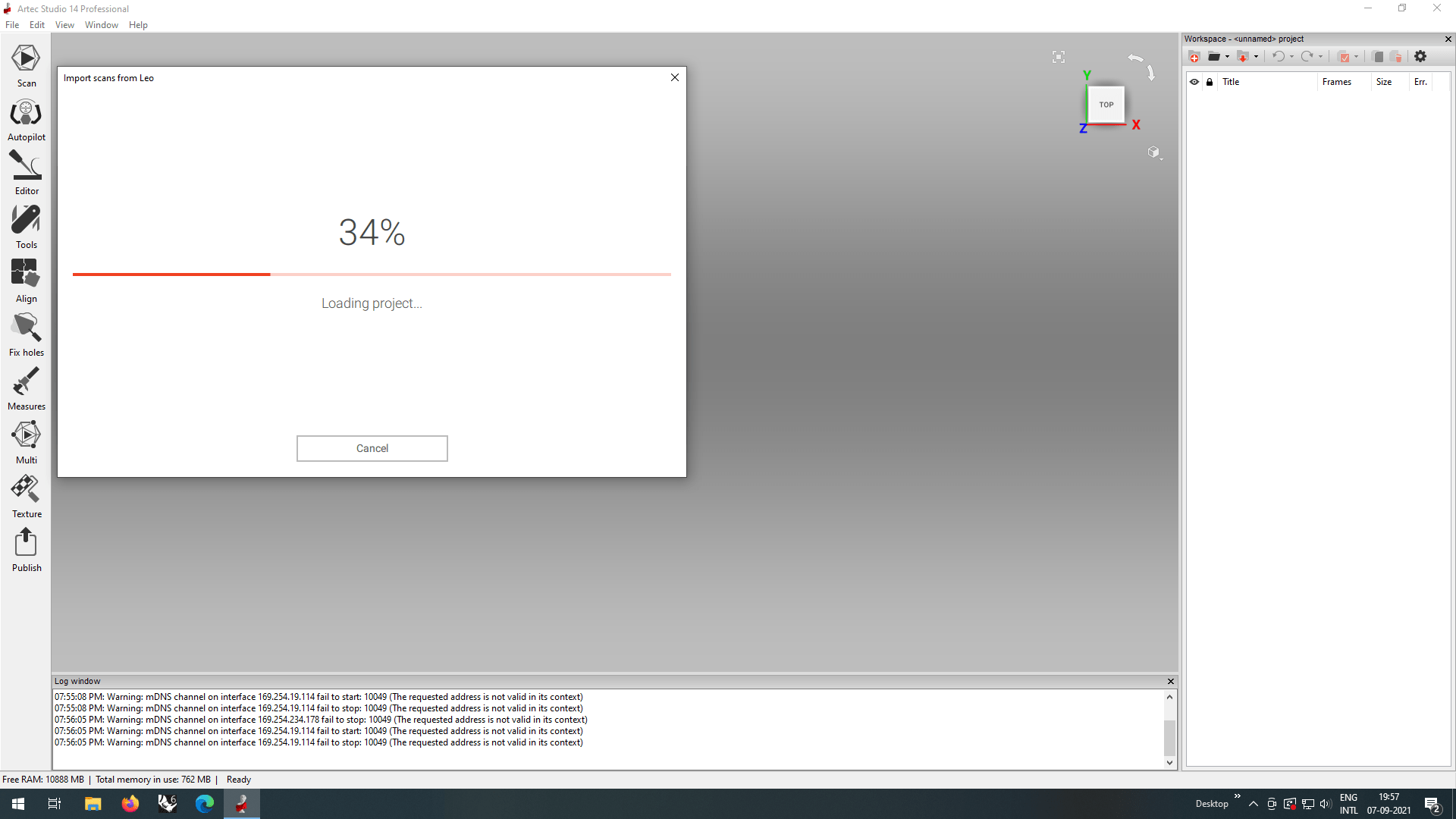
It started to import the file from the Leo scanner to the studio, Ethernet wired connection made a fast transfer the file size is larger than 1 GB.
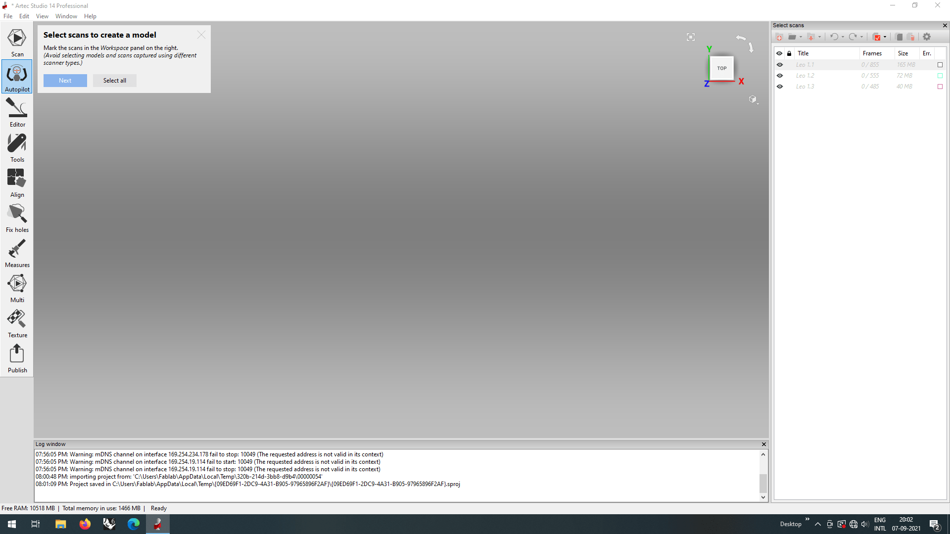
The Scanned files appeared in the left browser of the Artek studio its time for postprocessing. The Artek studio has many postprocessing features one of them is Auto pilot.So I clicked the option to tryout it said to select the scanned files I did select from the right browser then clicked 'Next'
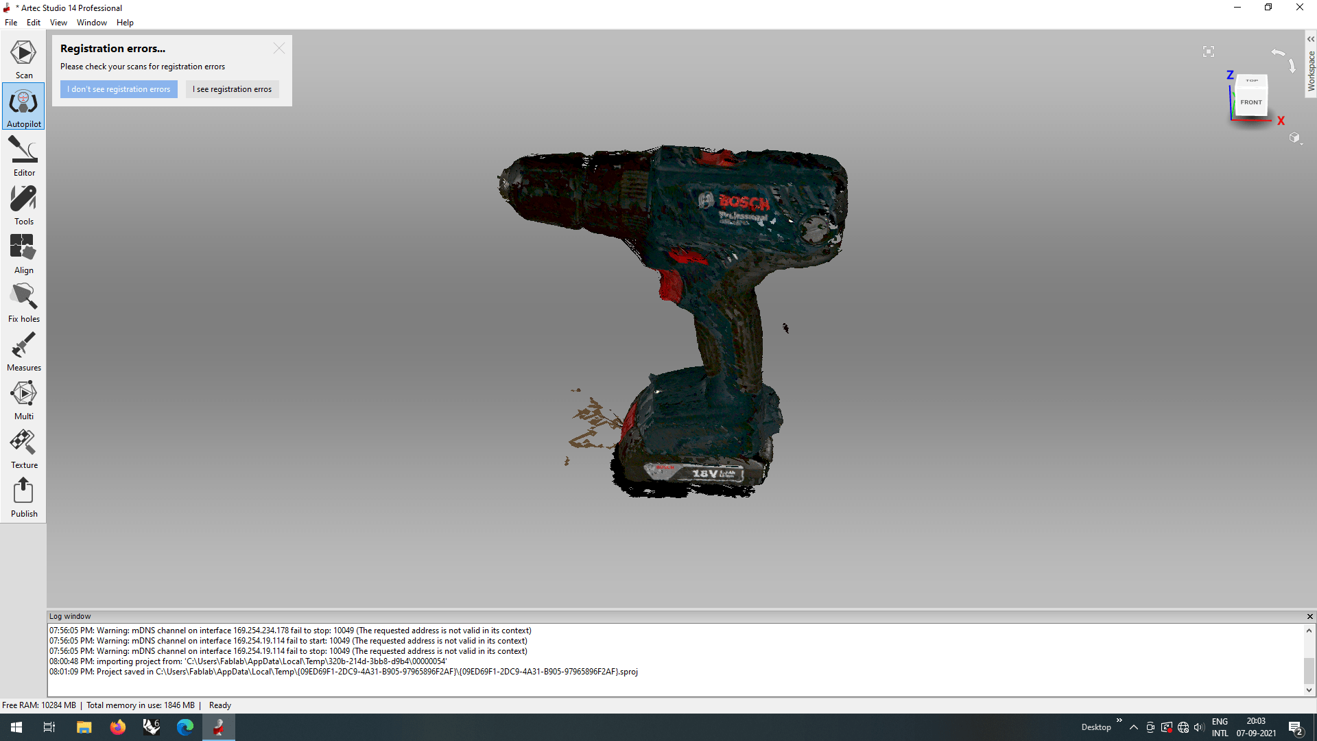
Then the model from the scanned files appears in the studio's window and asked wether I see any registration errors or not.Here the registration meant for the alignments of the three scanned files.So I clicked on 'I don't see registration errors' , if it is misaligned I have to click That 'I see registration errors'.
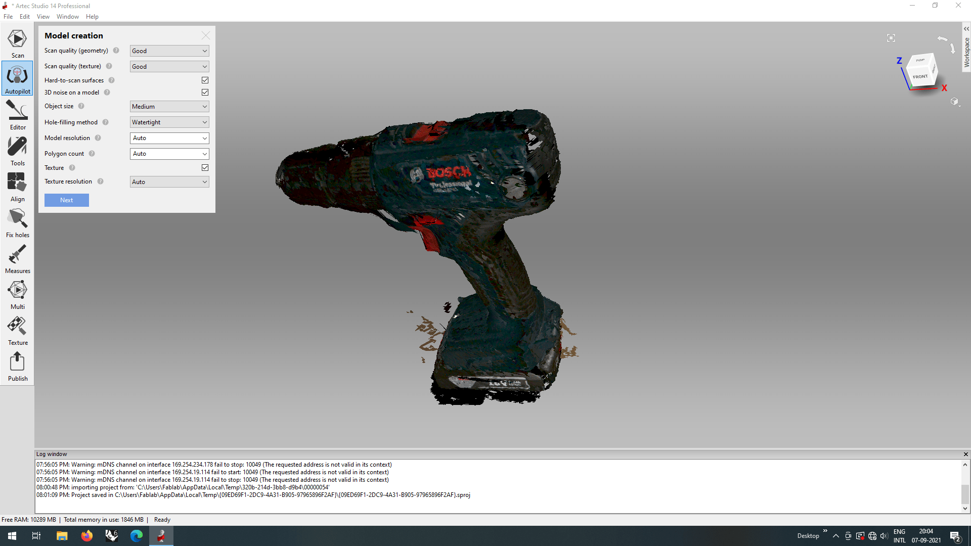
In the next step studio asked for 'Model creation' details so I entered the details like in the above screen shot.
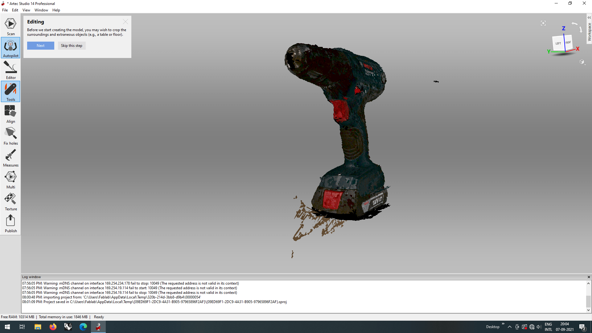
Next in the Editing step it asks to crop unwanted scanned noise from surrounding.So I clicked 'Next'.
The studio changed to an editing environment where we can remove unwanted noisy components from the surroundings.
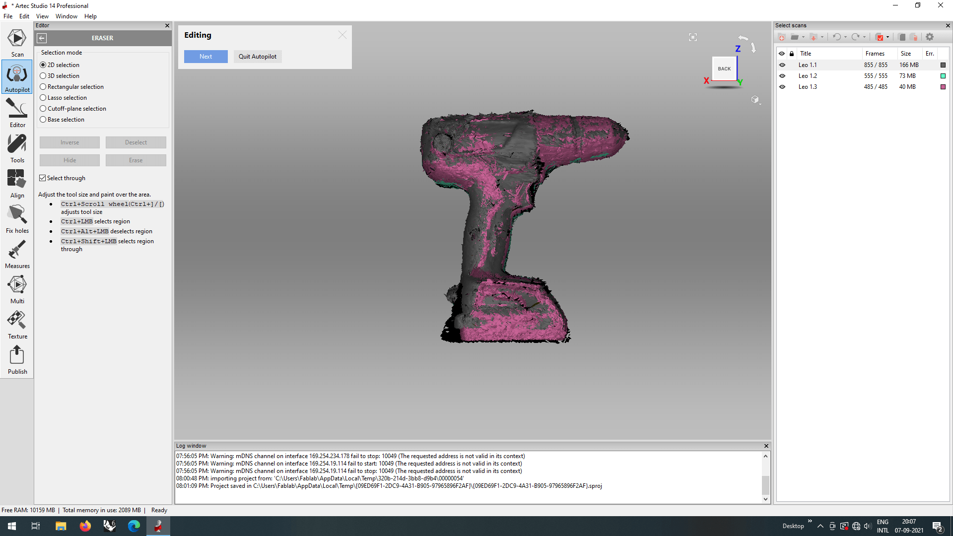
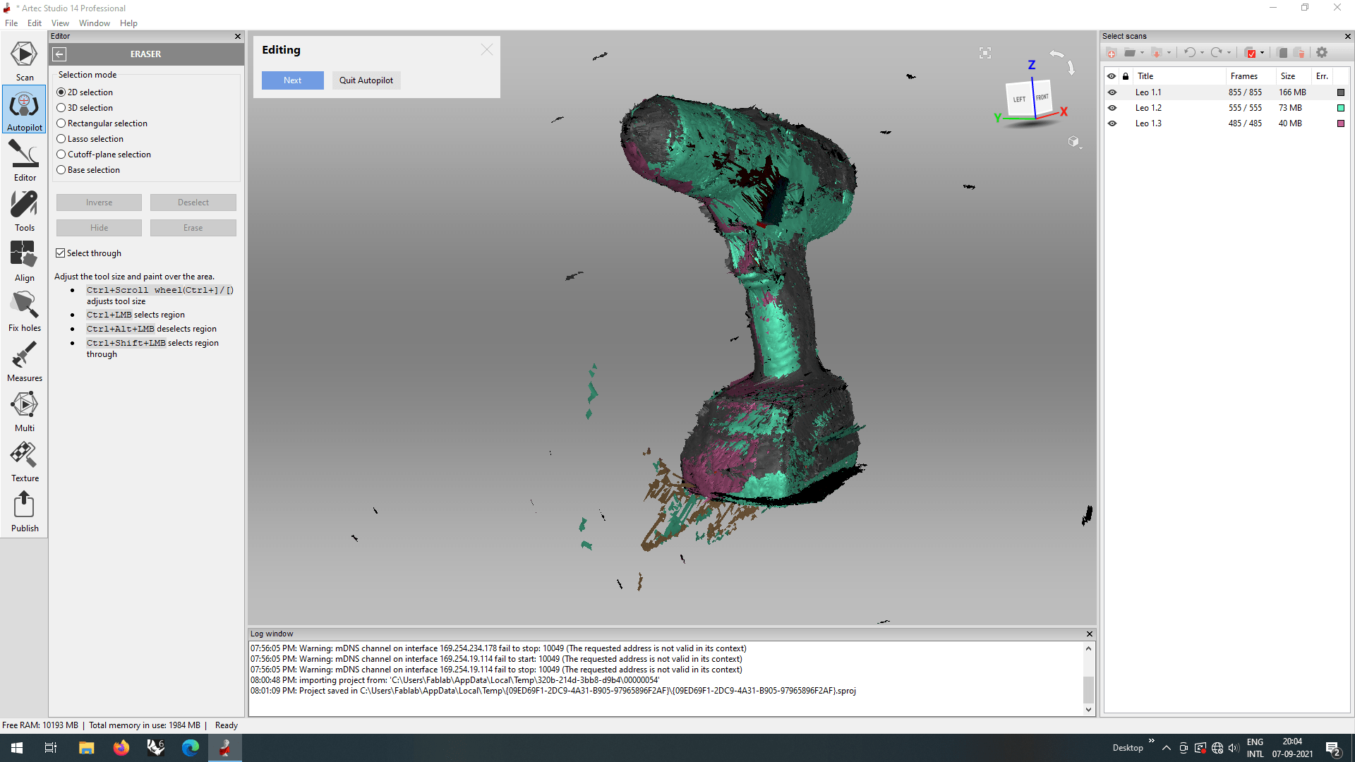
I opted the 2D selection and then painted hover the unwanted scanned noise like we erases in the photo editors to remove them. Then I clicked 'Next' to continue the auto pilot.
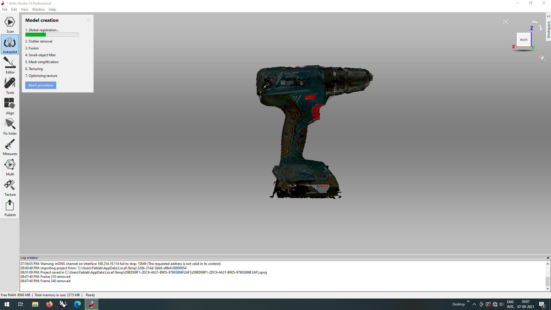
The auto pilot process begin for the model as first step it was started to align and bonds the 3 separate scanned files.
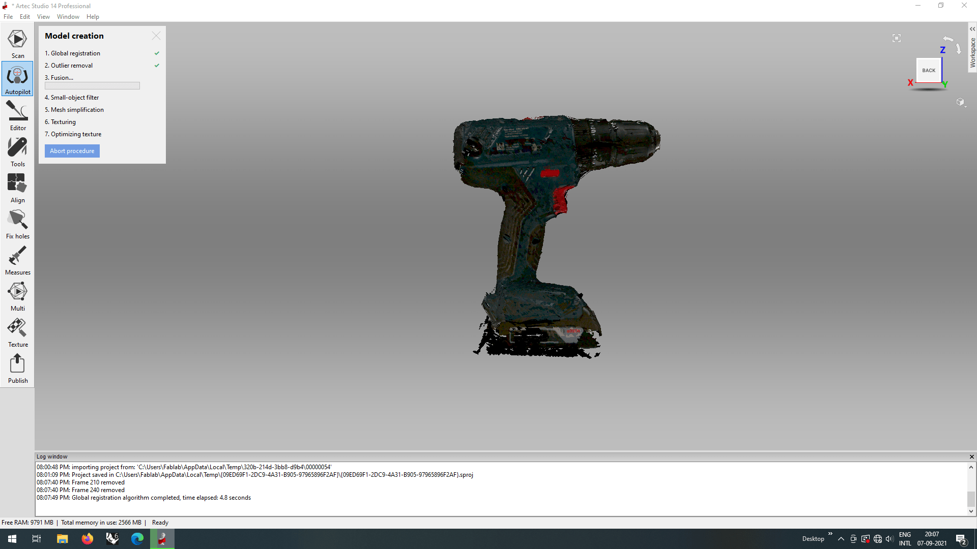
Then it continue for fusion ,where the all the scanned data fused together and filling holes ,smoothing surface to creating the final 3D solid.
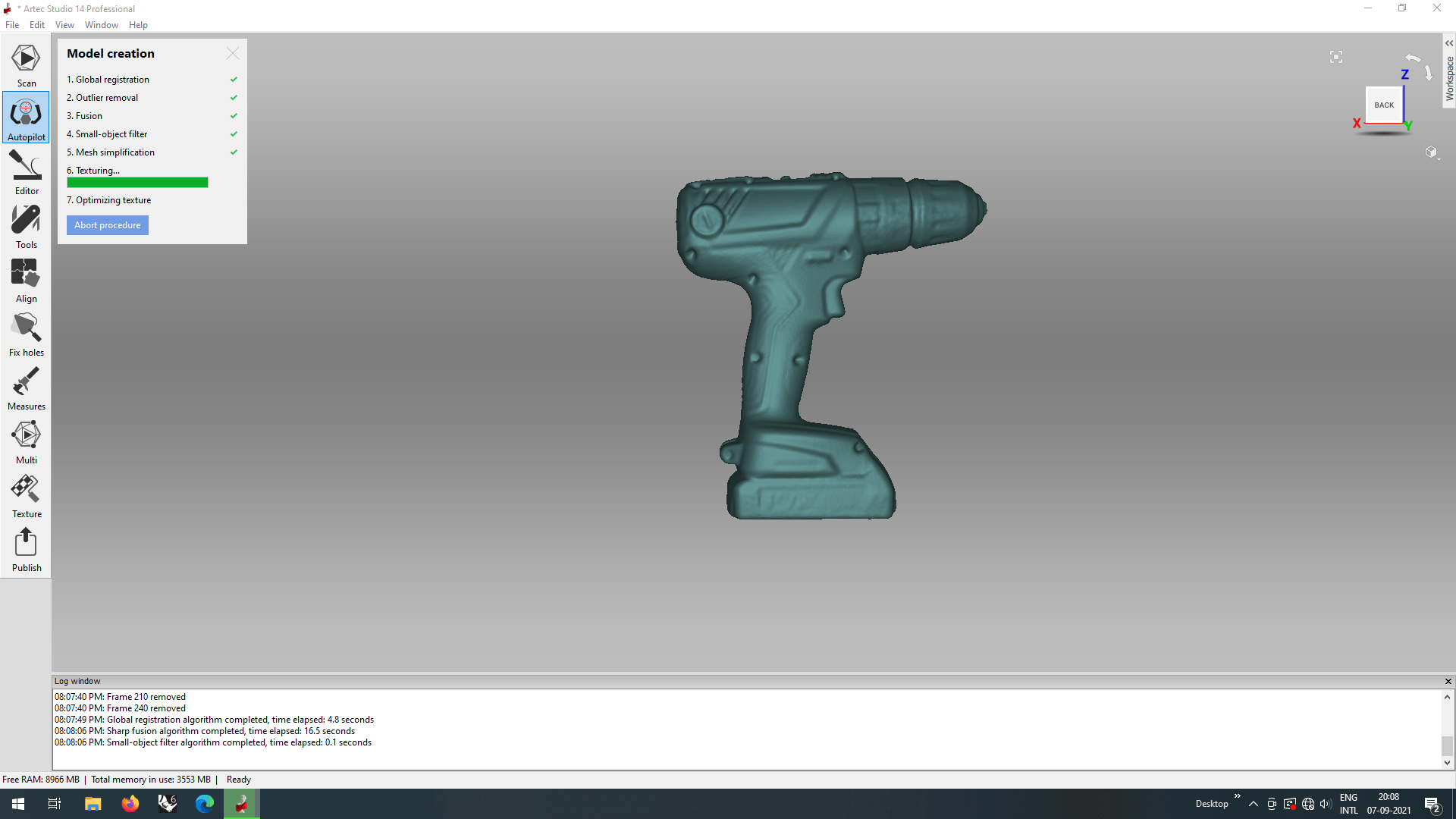
After the Fusion it started the texturing process for giving the detailed appearance all over the fused 3D Body. actually the fusion and texturing process takes time, for process also it depends the hardware configuration of the Computer.
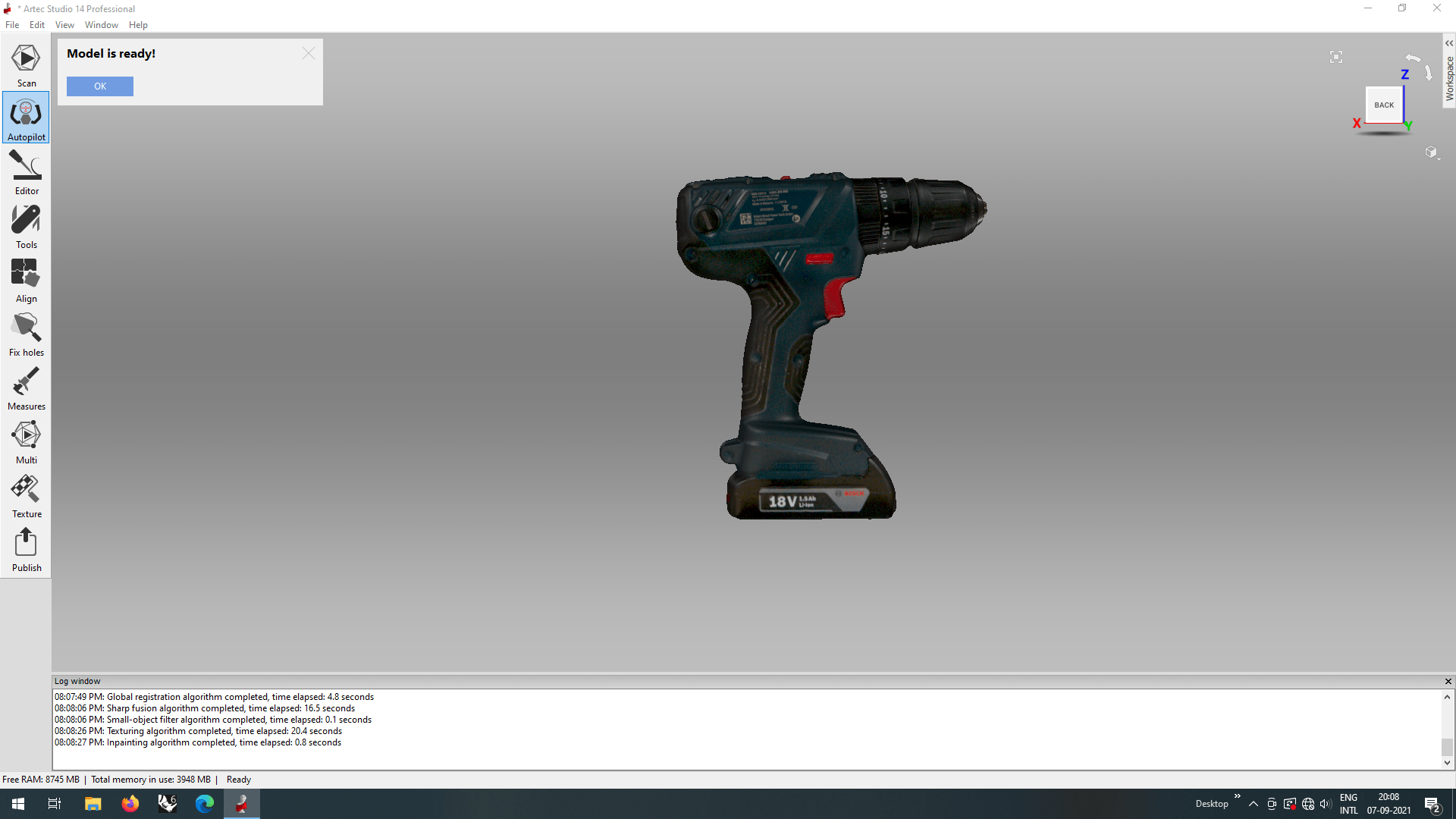
And finally the model is ready! its look perfect and smooth also good detailed texturing I love it!.
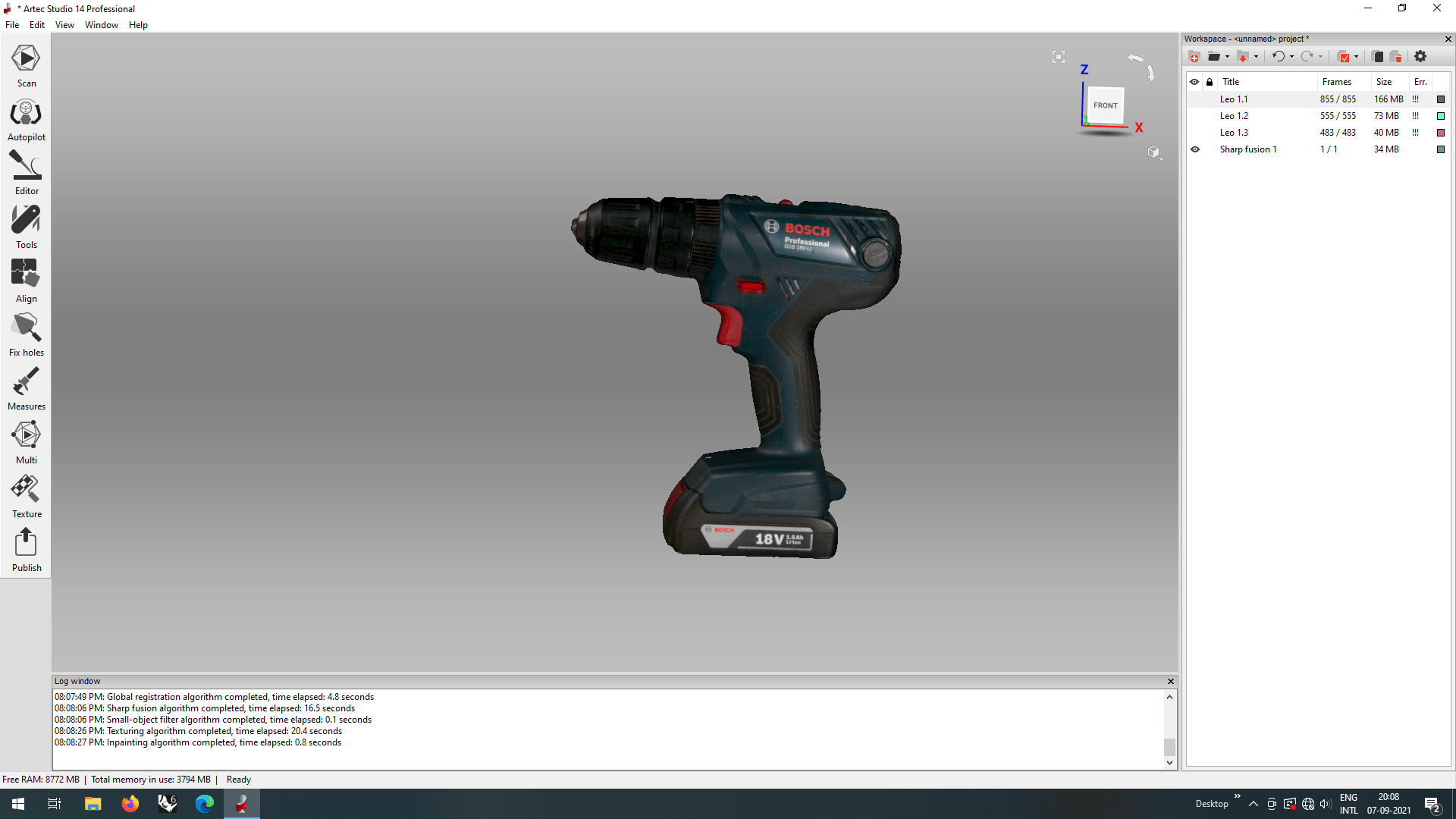
We can see the newly created component in the right browser of the artek studio. The project file usually a larger than 1 GB because the scanned file also larger upto 1 GB. I exported the final model as a '.obj' file which also export with the texture around.
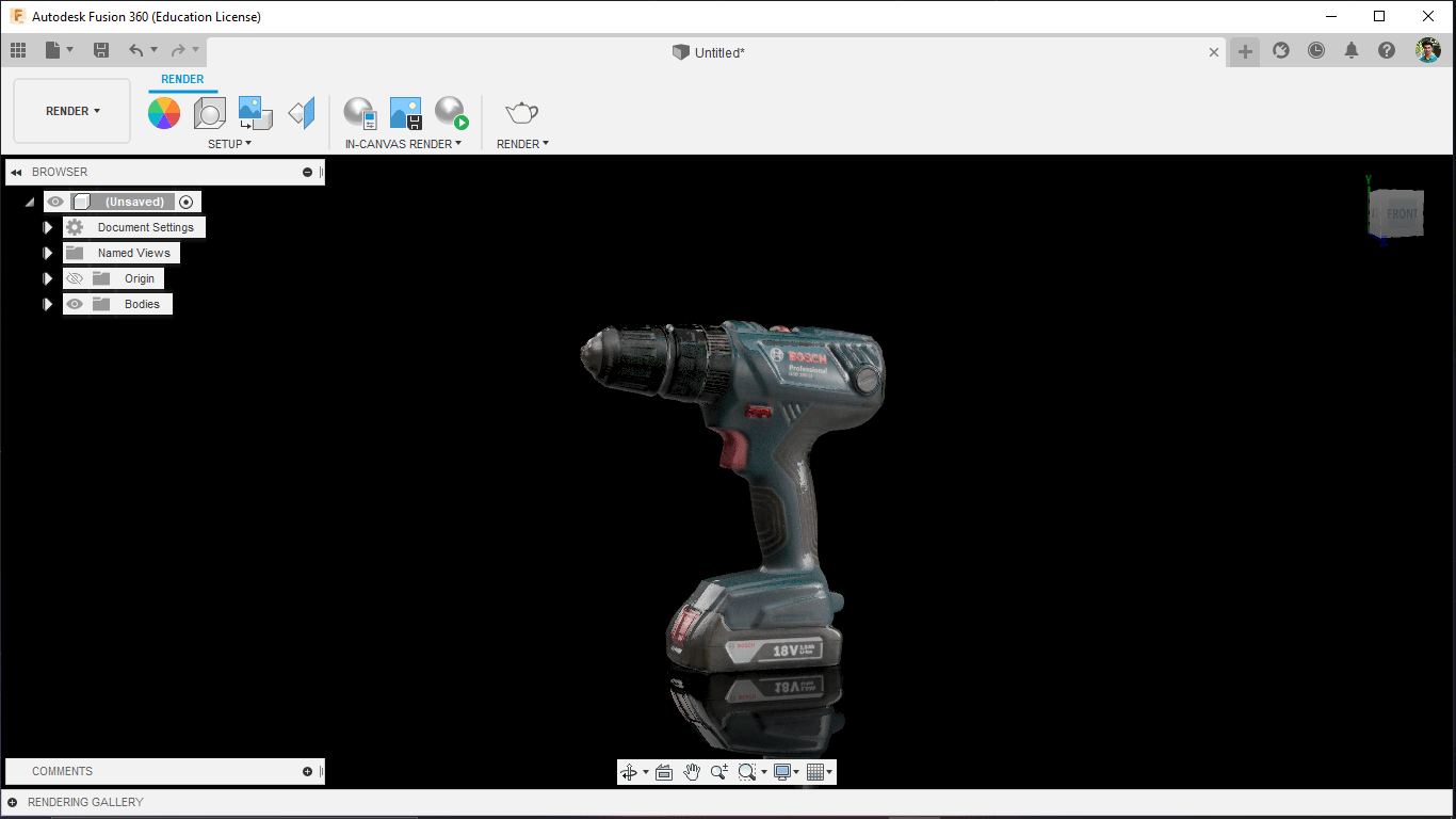
I opened the Obj mesh file in fusion's render environment and set up the background and exposure to render the 'obj' file also hav a beautifully texture.
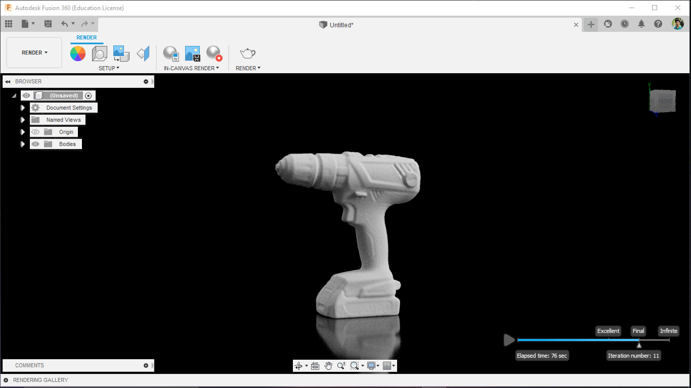
But the rendering of the fusion did not came out as expected may be I did some thing wrong.honestly I'm not good at fusion rendering or any rendering in 3D cads.
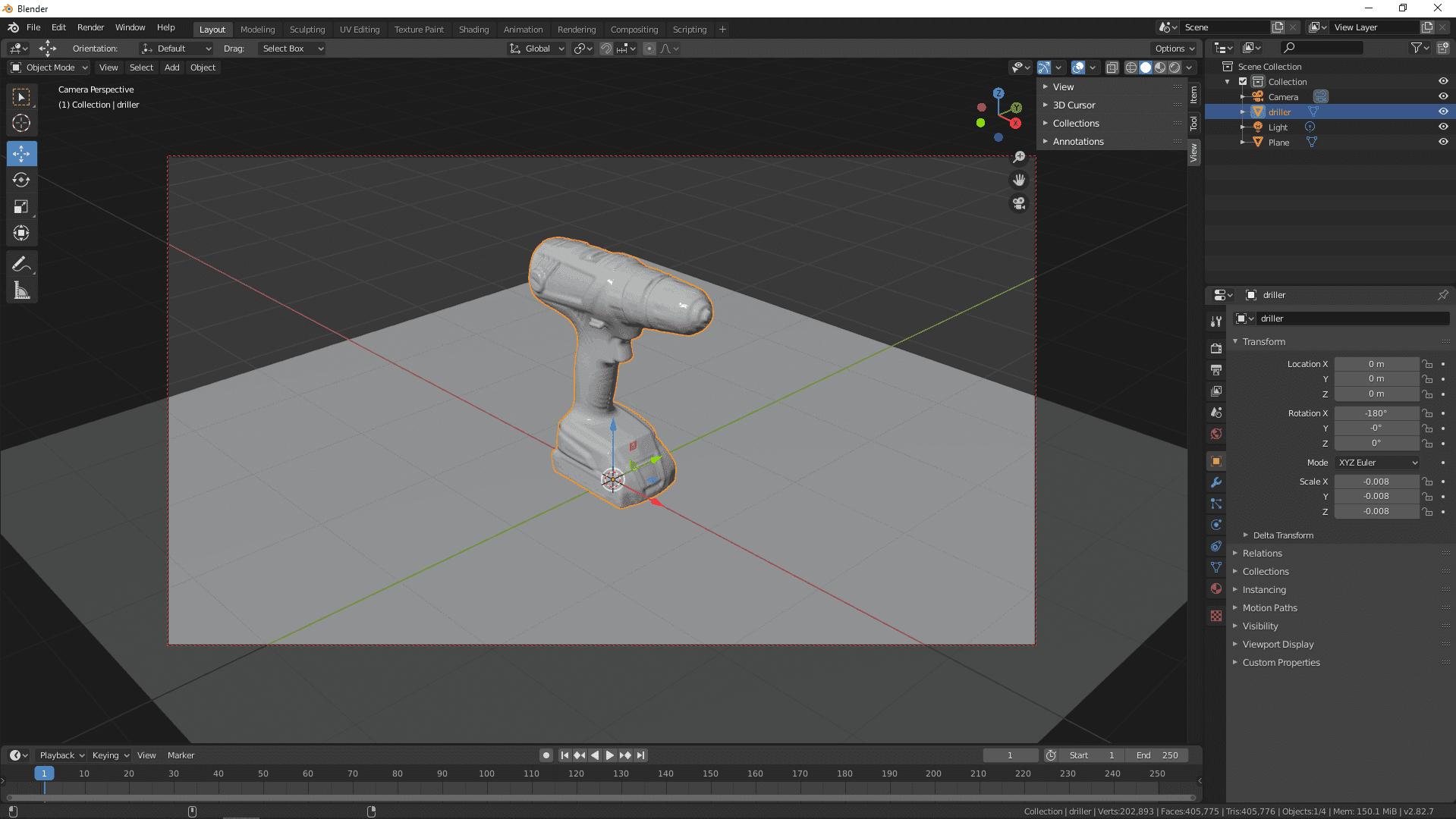
Any way I opened the Object file in to the blender environment and found a tutorial to learn how to render in blender.I followed a Youtube Video from a guy named Rory Allen
I did adjusted some settings of blender render environment and learned few blender tools. It's feel like not a big deal if I keep doing thing in blender
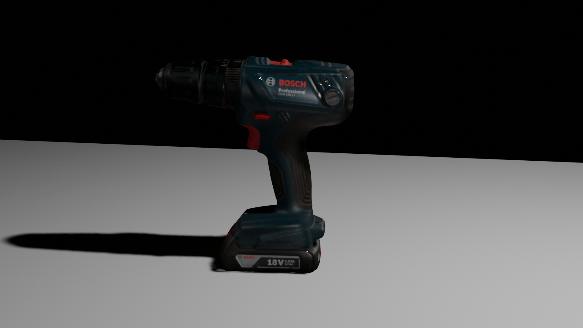
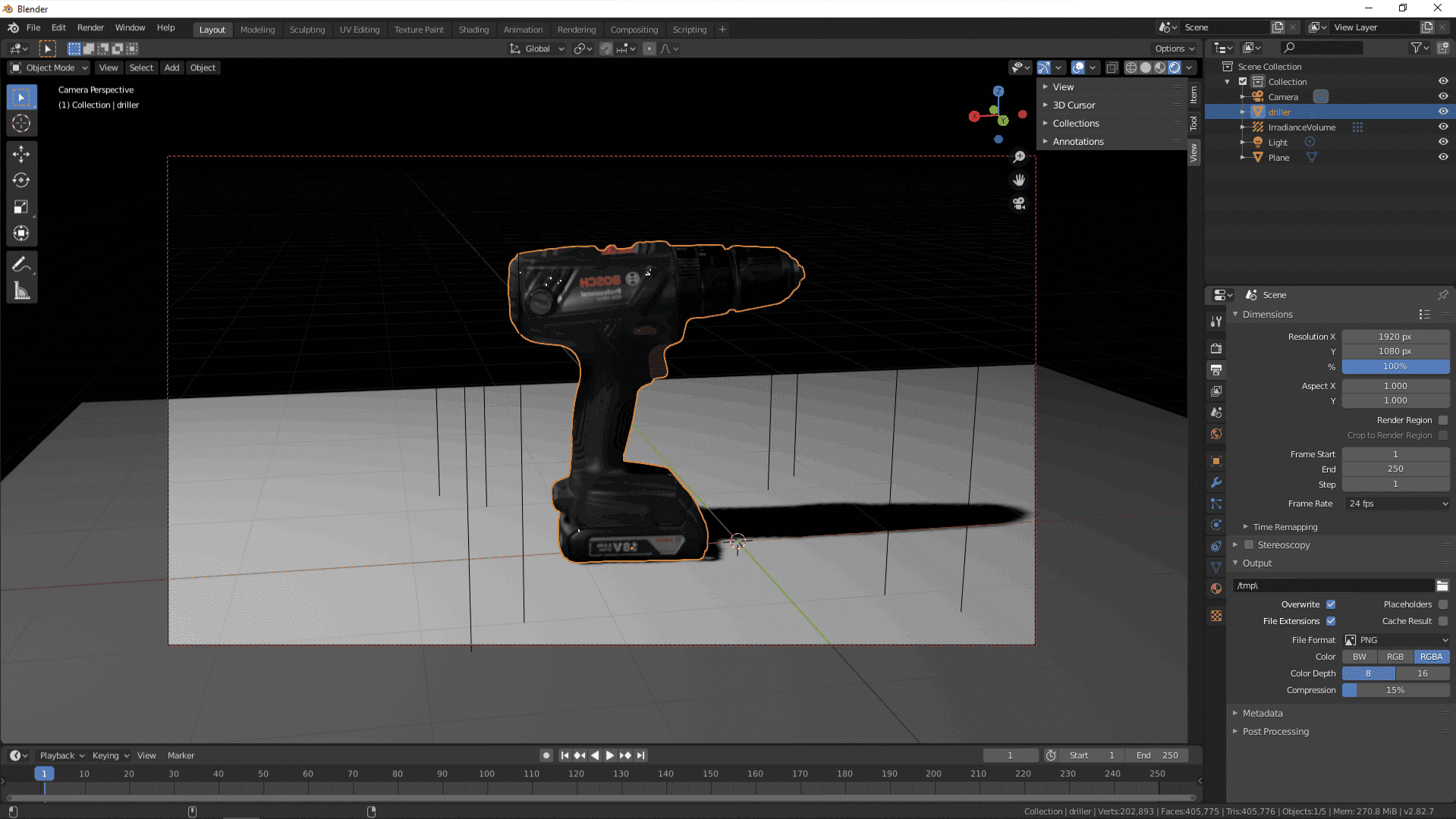
Here is the rendered output from blender. Actually the picture was mirrored from blender no idea what happened then I mirrored to make it right with the help of an image editor tool. It's really awesome feel's realistic this is how we bring realistic object in the 3D world .
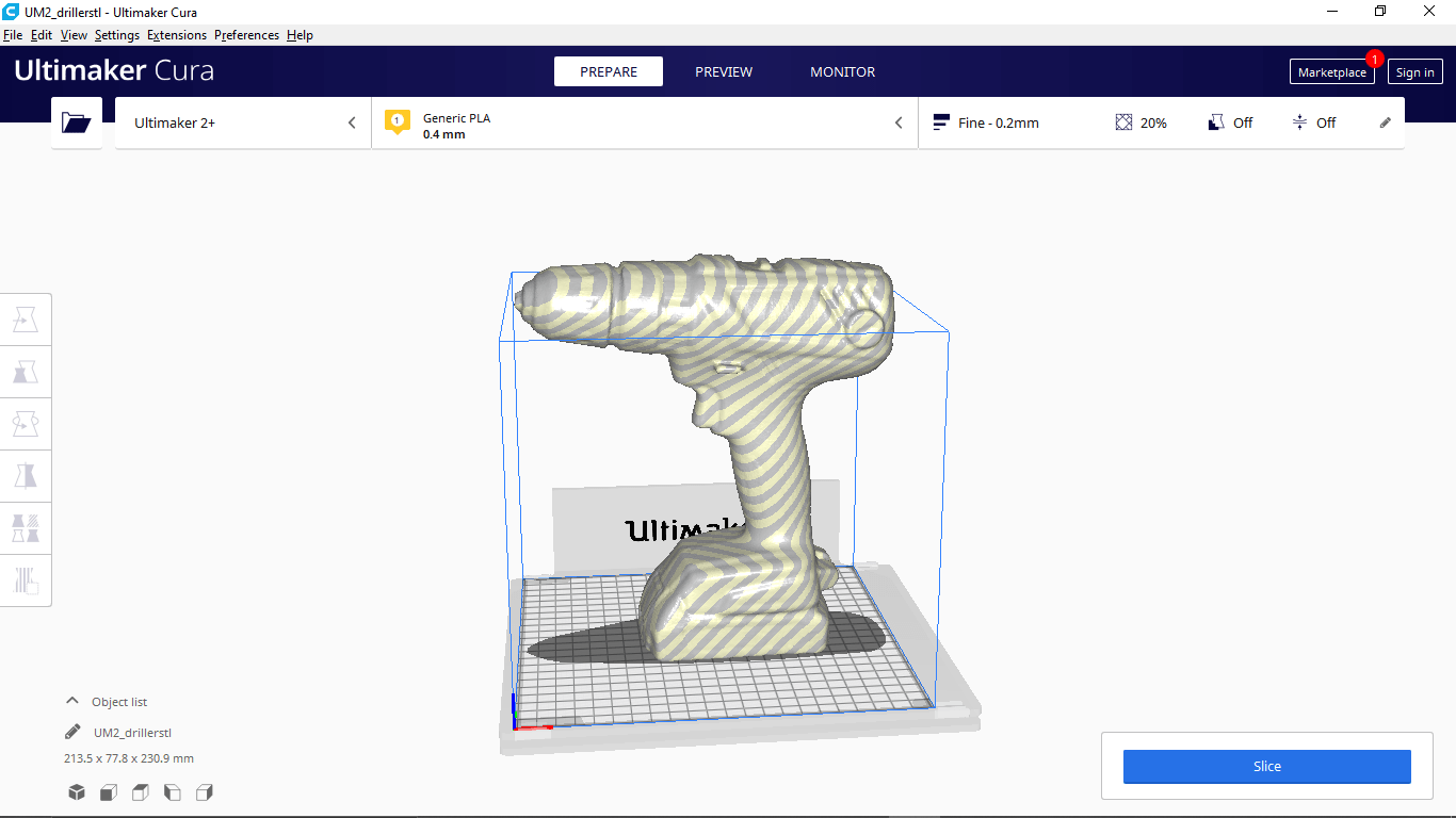
I'm also exported a '.stl' file of the model from Artec studio for trying 3d printing the object i scanned and Opened in the Cura slicer but it's look like the size Is too large fo the printer.
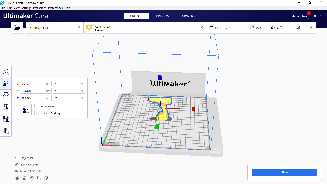
I reduced to one fourth of the original size (to 25%) to fit in the 3D printer as well as reducing the print time to not waste any print material just for a comparison print.
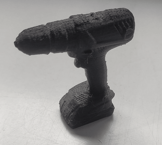
Then I printed out the scanned model with support and removed the unwanted support material after the print here is the results.The details of the scan are pretty much impressive!.
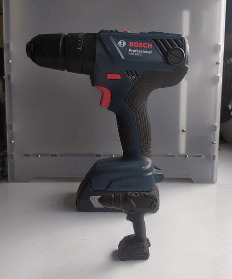
The comparison picture shows how accurate the scanned model to the original. This Scanning methods very help full to bring any real world model in to the cad environment so we can Reverse engineer the design and also there are many possibilities like we can build custom add-ons to the Model.
References
- Fab Academy 3D Scanning and Printing classes
- Ultimaker 2+ Connect
- Ultimaker Cura
- Original Prusa i3 MK3S+
- PrusaSlicer
- Artec Leo
Downloads
- 3D Printer Test Files
- 3D Printable Bracelet Files
- 3D Scanning Files