Computer Controlled Cutting
week 3 group assignment is to characterize our lasercutter's focus, power, speed, rate, kerf, joint clearance and types
Overview
So this week we are gonna design and make 2D objects by using cutting machines.Mainly focused on Vinal cutting and Laser cutting process. So with the the help of the instructors we Learned about the machines that we are gonna use this week.
Laser Cutting
Laser cutting is a type of thermal cutting process which use a focused laser beam in the cutting area to melt the material and then a gas or Air used to eject the molten material for making it cut.
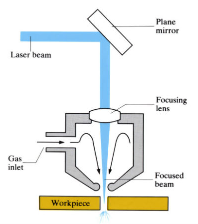
The above figure shows a basic components of the laser cutting machine's nozzle. The machine is based on a 2 axis CNC it will have two motors to drive each access according to the given x,y coordinates. Laser machines are widely using today we can see them near by Acrylic or wood working shops. They available in different shapes and different power that totally depends the material being used to the cutting process.
Trotec Speedy100
In Our FAB LAB we have two different types of Laser cutting machines.One is used for the FAB academy it can Cut Acrylic,wood,cardboard...etc. The other one is Fiber laser cutting machine part of the Super Fab Lab It can engrave circuits to make PCB. Both are manufactures by same company But,little more power full than the other one
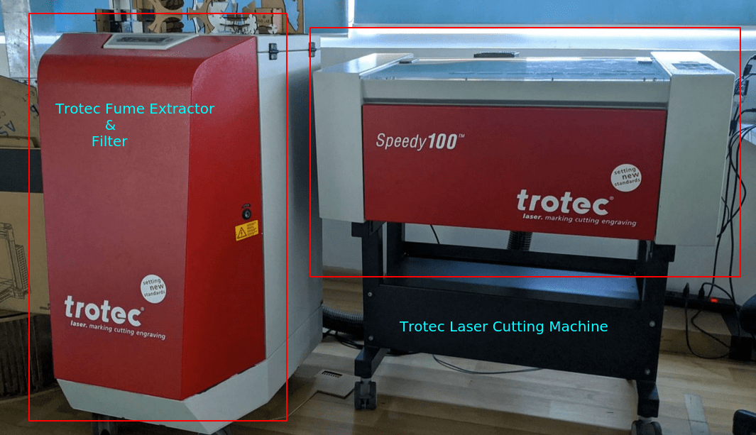
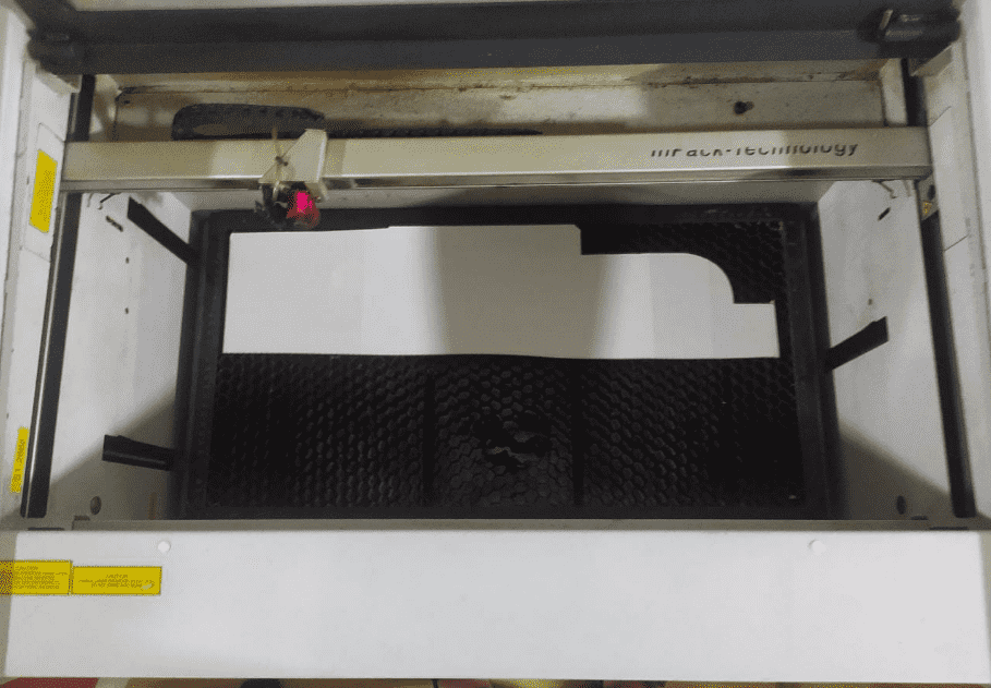
In the figure shows the Laser cutting machine setup from Trotec using in our LAB Mainly it has two component one tis the Trotec Speedy100 CO2 laser cutting Machine and another one is a Fume extractor & Filter which connected to the Laser cutting machine. It helps to extract the fumes which creates during the process then it filter the fumes to remove the carbon contents
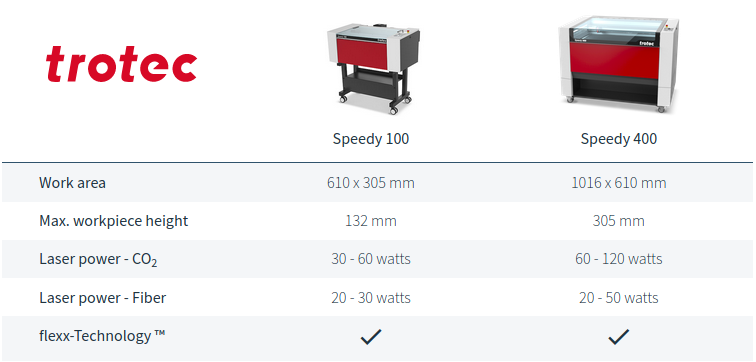
The other machine at the super Fablab named Speedy400 quit powerful than the speedy100 as shown in above and also have larger work area
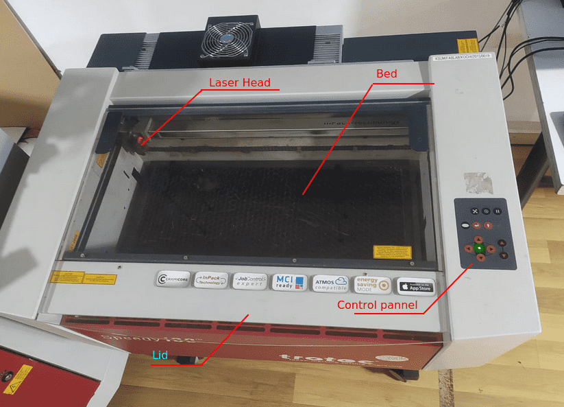
These are the main user components to aware the Transparent lid and inside a hexagonal mesh bed ,moving laser head,control panel etc..
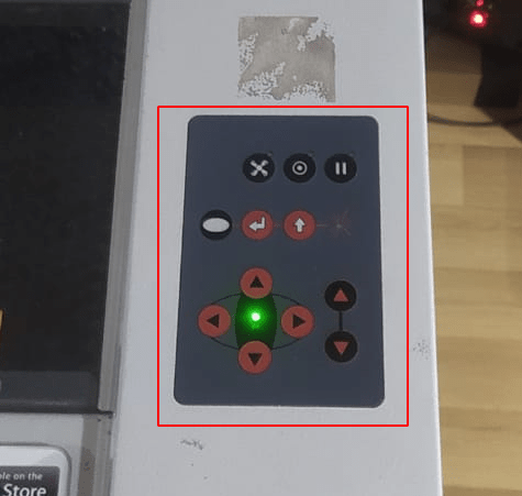
This is the control panel for users to move the laser head for selecting the work area. And also some other controls as well to control FAN ,pausing controls,z axis bed leveling control etc..
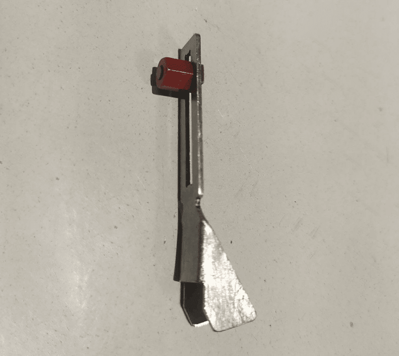
To cut different thick material the laser head and the work needs to be in focus distance.This tool is the focus distance of the speedy-100-laser machine. We have to set the focus manually for each different thick material
Kerf of the laser cutter
like I said laser cutting is a kind of burning process. So, burning melt the material which cause shrinkage and material loosing effect on the cutting material. this phenomena will effect the end results.So, we should adjust the loosing measurements in the design and that is called kerf.
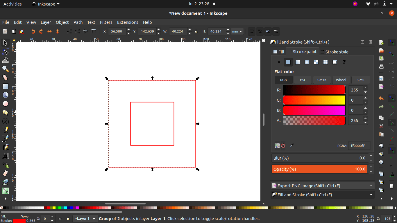
We created a vector file of a 20 mm square inside a 40 square in Inkscape .The test is all about measuring the square inside the 40 mm square without Inside Fill and find out how much the width of the laser beam passing line.Then changes it's stroke color to proper RED and Stroke style width to 0.1 mm
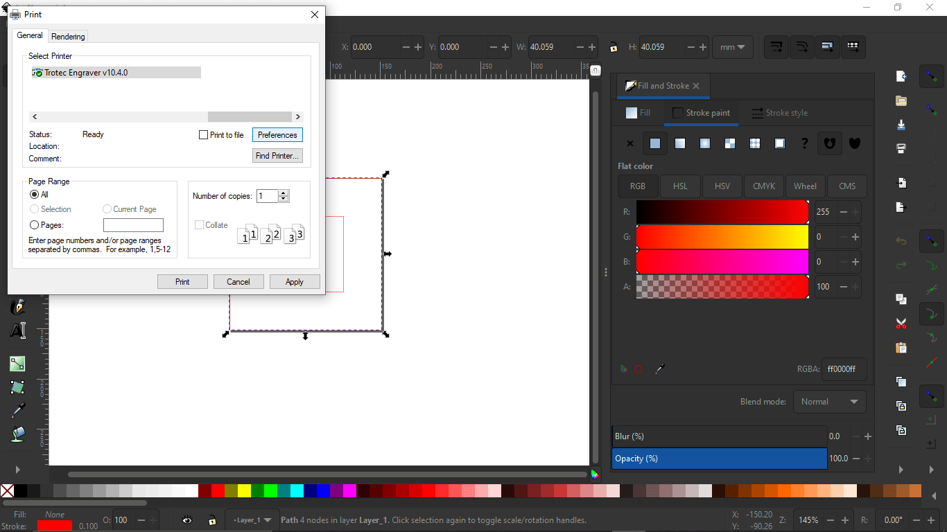
Then we send the file to Trotec interface software from inkscape like we used to print by selecting File >> Print.Then selected the 'Trotec Engraver v10.4.0' and opened the preference
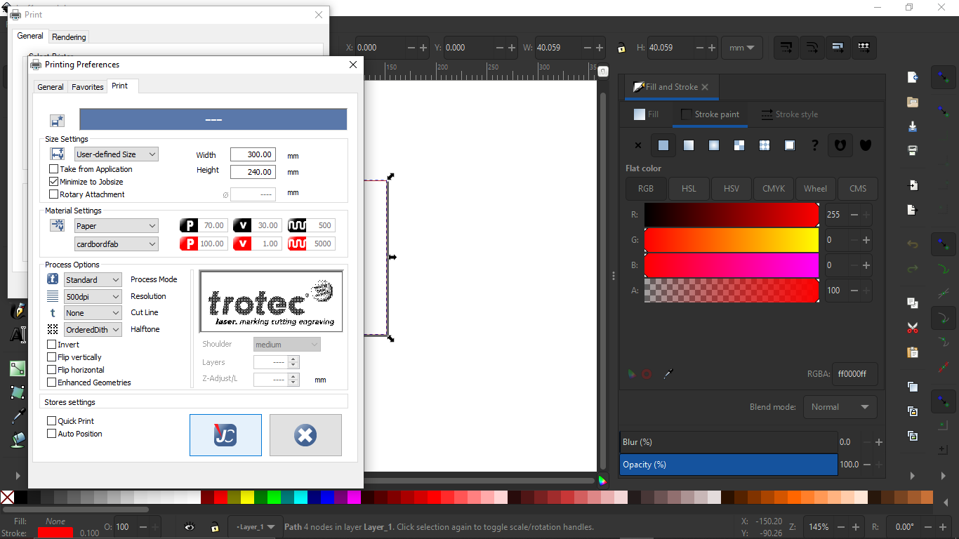
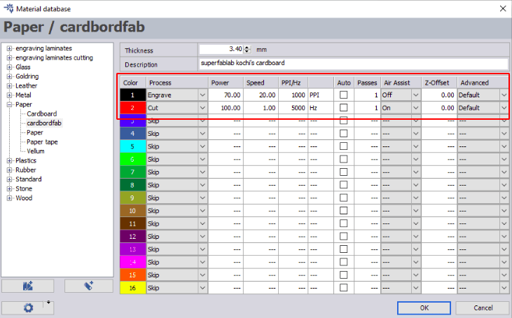
In the preference window we can select the material and other properties we are cutting on a cardboard sheet. After selecting updated the setup by clicking the Trotec 'JC' logo button.
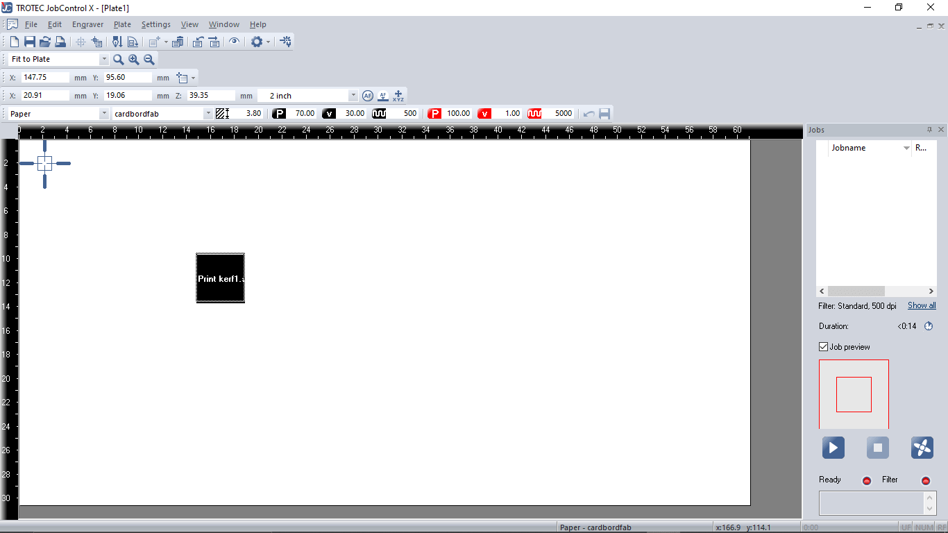
After clicking the print the Trotec software opened automatically with the file
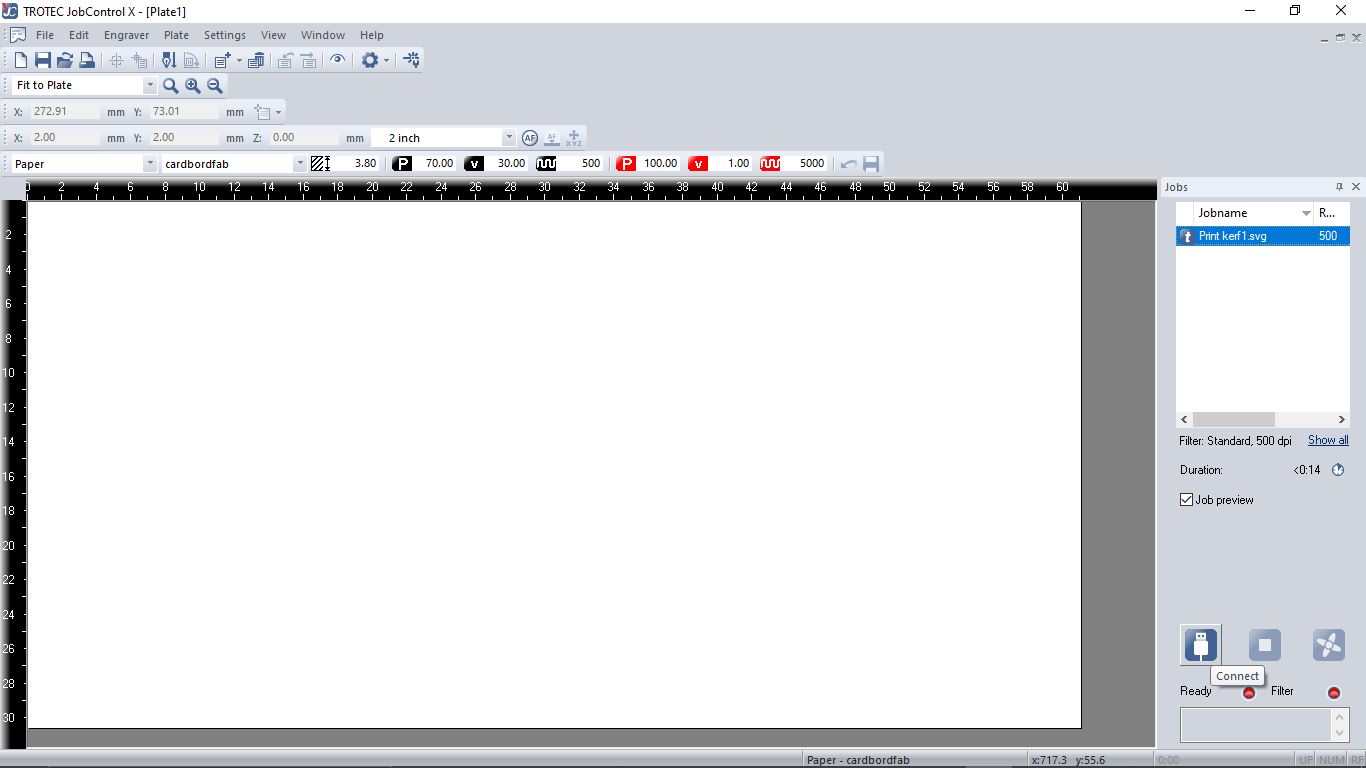
The softwares shows the dimensions of the Engraver's bed and also shows the material selections and power,speed etc.. On left we can see the file in te job list .So as next step we connected the laser by turning the Engraver's power switch on and then hitting the connect button in the software.It's mandatory to close the lid of the Engraver to complete the intital homing setup.
After the software made a connection with the speedy100 the pointer which represent the laser head show up on the software's work area.we can manually move and can decide where to cut it also moves in software
Then we placed a pice of card board on the bed which is smaller than the bed size . And then we rise the bed towards to the laser head using the Z axis bed up-down arrow keys on the control panel.
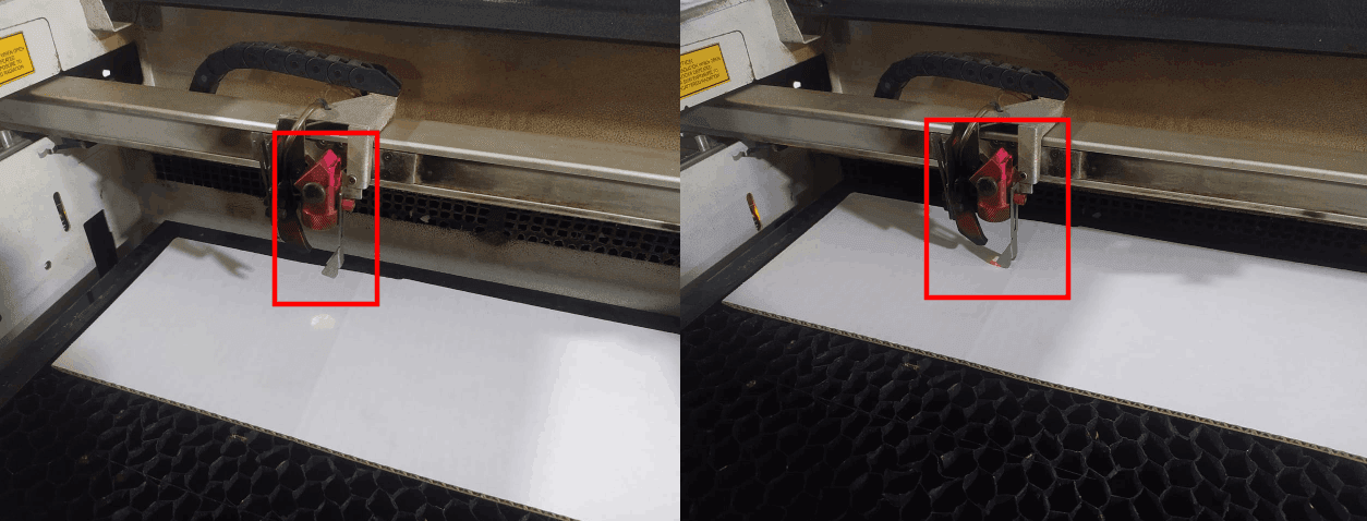
When the focus distance were aprox 15-20cm we placed the focus tool on the laser head and continues rise the bed slowly till the tool touches the cardboard
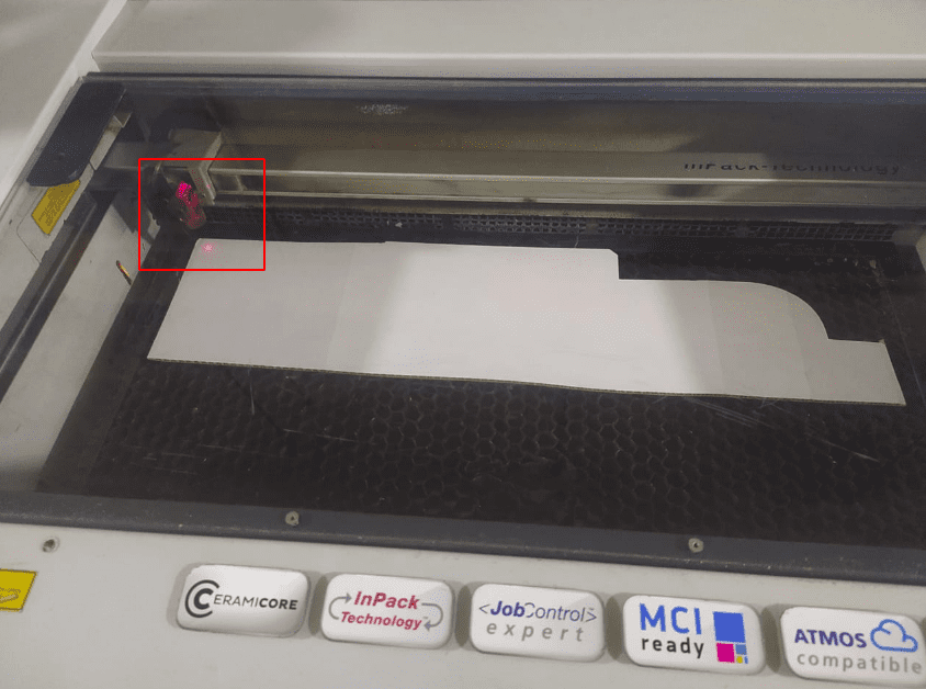
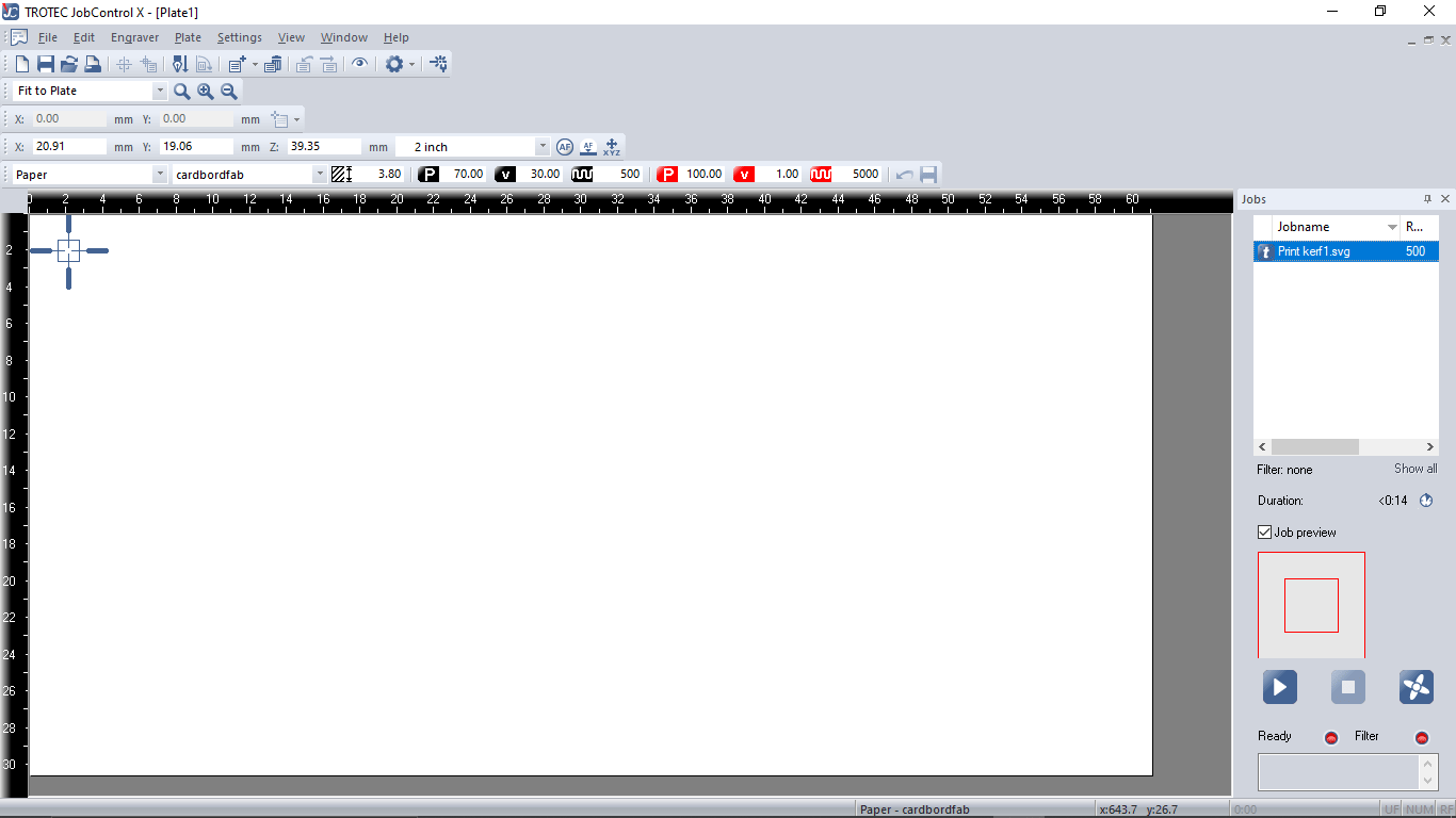
After the focusing is done we moved the head to origin position manually. A small red color laser dots helps to show the cutting point on the job
Then we drag the kerf-cutting-file from Jobs section in the Trotec software towards the pointer on the screen
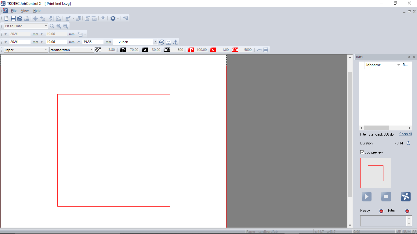
If we double click on the job we can see and double check the file before cutting.
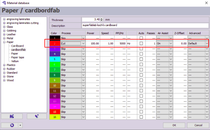
This is the Engraver cutting setup the red color is for cutting job. velocity 1 is set for the 3.4 mm cardboard
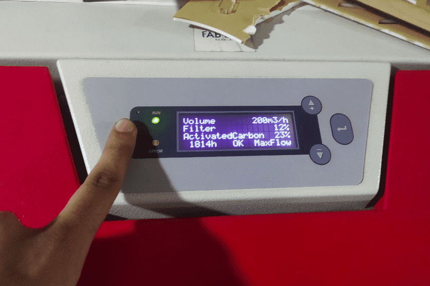
we turned on the filter before hit send to cut . Normally the Filter will turn on automatically when we send the file But in our FAB LAB not connected to machine to teach students the importance of the filter
After sending the file the laser head moved to home position and started cut.And it finished in 14 sec (the above video is 2X times faster)
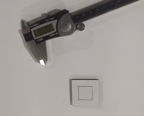
Then we taken out the laser cut cardboard parts from the bed and measures using a digital vernier caliper
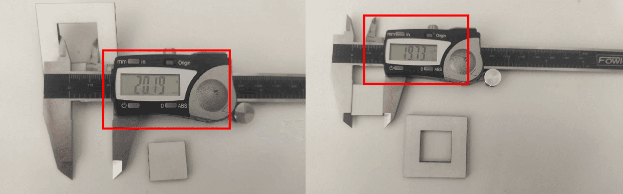
So we did math decreasing the outer dimension from inner dimension
- 20.19-19.73= 0.46
- o.46 is the total kerf
- kerf=0.46/2
- kerf=0.23
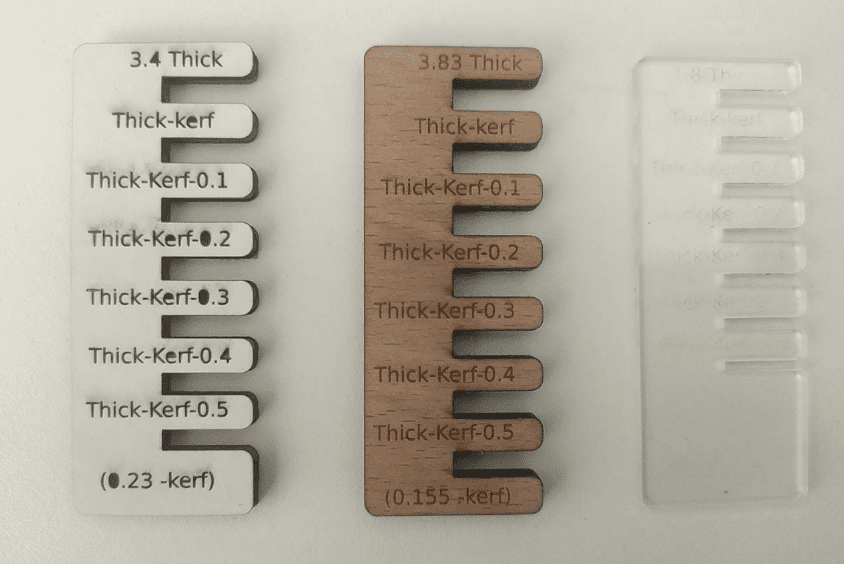
we also tried out other materials as well 1.8 mm acrylic and 3.83 mm Birch wood and calculated the kerf
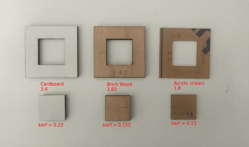
The cutting power of each material is also different all the information according to the material given below
Cutting and Kerf Details:-
- 3.4 mm cardboard
- power = 100 %
- Speed/velocity = 1.0
- Frequency = 5000
- kerf=0.23
- 3.83 mm Birch Wood
- power = 100 %
- Speed/velocity = 0.35
- Frequency = 5000
- kerf=0.155
- 1.8 mm Acrylic ( clear )
- power = 100 %
- Speed/velocity = 0.5
- Frequency = 5000
- kerf=0.13
Press Fit Test
For making a good joints in laser its good to know the press fit tolerances of each material. To test that we designed a Test jig design in fusion 360.
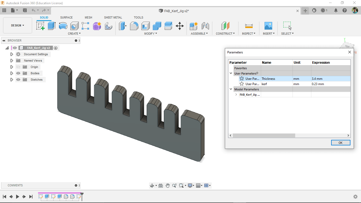
The design made with parametric thickness and kerf variables.So we can change the design for any material to check its press fit.
we created a new sketch on the surface and saved in dxf format to cut in laser
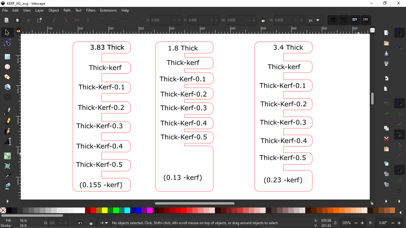
Then opened each dxf in Inkscape and added measurement details to engrave on top of it.The engraving job kept in black color and cutting kept in red
Opened each in the Trotec software and setup the engrave settings, then Engraved and cuts them out starting with cardboard
The engrave speed vary according to the material just like the cutting speed here the cardboard engraved more than other two and the clear acrylic jig is the less visible because of it's material property
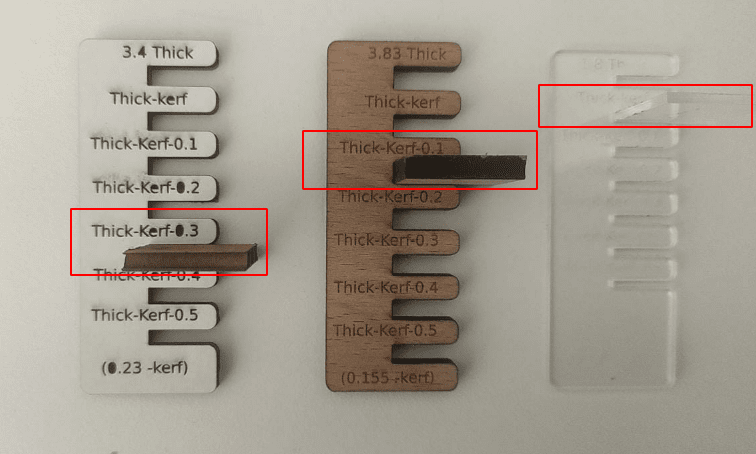
We tested each jig with a pice of material which we cuts for finding kerf and found the press-fit values
Engraving and Press-Fit Details:-
- 3.4 mm cardboard
- power = 20
- Speed/velocity = 20
- Frequency = 1000
- Press-fit=(thick-kerf-0.3)3.4-0.23-0.3=2.87
- 3.83 mm Birch Wood
- power = 75 %
- Speed/velocity = 80
- Frequency = 1000
- Press-fit=(thick-kerf-0.1)3.4-0.23-0.1=3.575
- 1.8 mm Acrylic ( clear )
- power = 75 %
- Speed/velocity = 60
- Frequency = 1000
- Press-fit=(thick-kerf)1.8-0.13=1.67
- Force
- Speed
- Force: 80 g
- Speed : 10 cm/s
Vinyl Cutting
Vinyl cutting is one of interesting process that we can cut any 2D images or vectors in vinyl with a computer controlled cnc machine which has a controllable pen knife
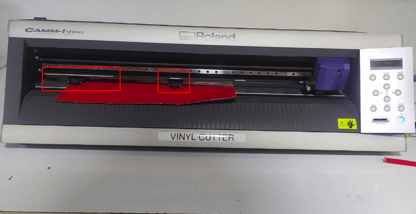
Roland GX-24 Vinyl cutter machine
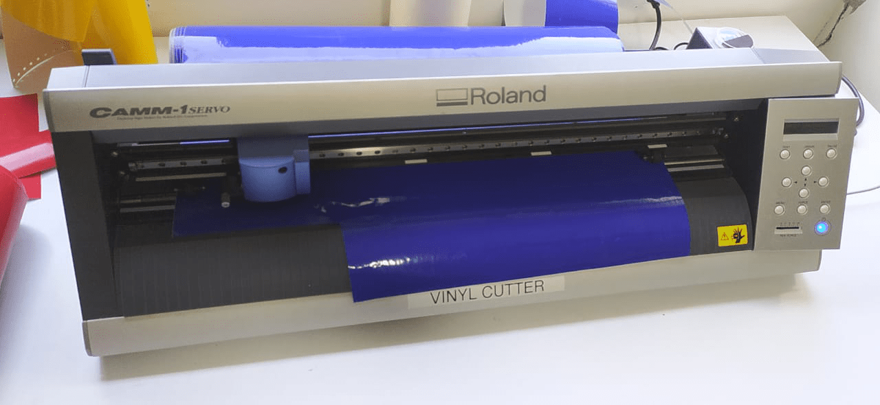
This is the type of vinyl cutting machine used in the lab. When we talk about vinyl cutting machine basically two type of machines available .One is active and other one is Passive. In the active machine the cutting blade turnings controlled by a controlled servo mechanism. but in passive the turning technology is like a roller coaster tyre .If it the entire head moves across a plan the blade will turn to that direction. Roland GX-24 is a passive blade type machine
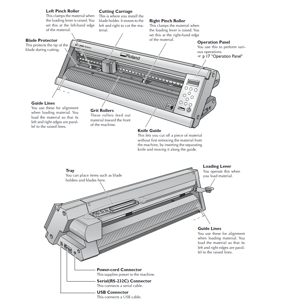
The above picture shows the part details of the roland GX-24 machine.It's a servo motor based high speed machine
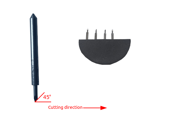
Blades are very pointy and sharp for cutting with 45 degree angle to the cutting direction like in the picture. Blades cutting angle also available in 30° and 60° also,In Fab we use 45° cutting angle blades
There are two parameter which needs to be adjust while we cutting vinyl according to the material specifications.
Speed is depend the force we are cutting in the machine also depend the material surface and quality.Also we cant give too much force that will damage the entire vinyl and also damage the vinyl cutter tool.So we did a Force test on the vinyl sticker from our Lab's Inventory.
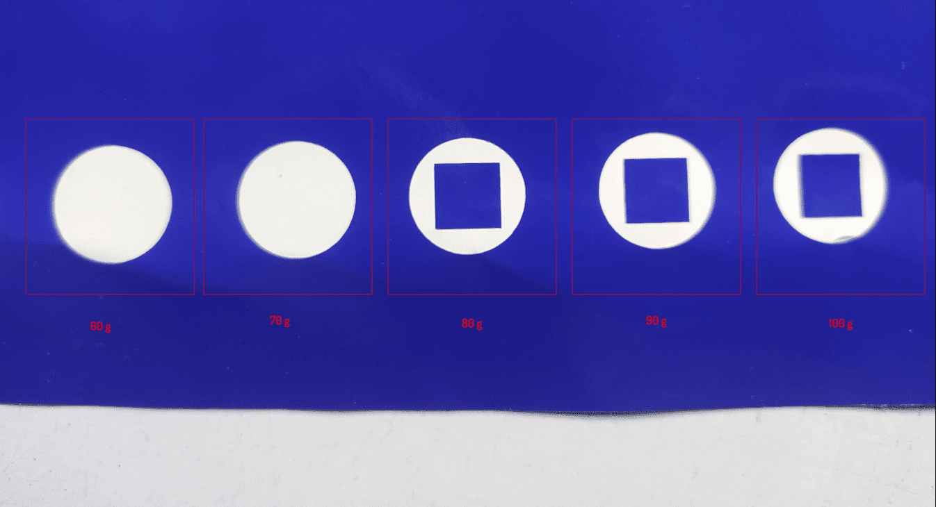
The test success is calculated to remove the circle shape without damaging the inner square shape like in the above figure. In the figure theres 5 different tests with different forces. From the result 80g is the best to cut in this material
Roland Cutting specifications:-
The force will vary if we increase the speed thats' also leaves uncut edges or over cuts sometimes. we can change those speed and force in the Machine menu and also there is a button for test cuts.
FAB MODS
Fab mods is an open source web app program which used as machine softwares or driver works with web socket technology. the mods replaces the window software to the machine which provides the machine manufactures to cut or mill the given image or vector file.so the prof.Neil mentioned about it to try out the fab mods from github in our pc.So I cloned a copy of the project into my PC and given a try to cut the vinyl using the FAB cutting machine called Roland GX-24
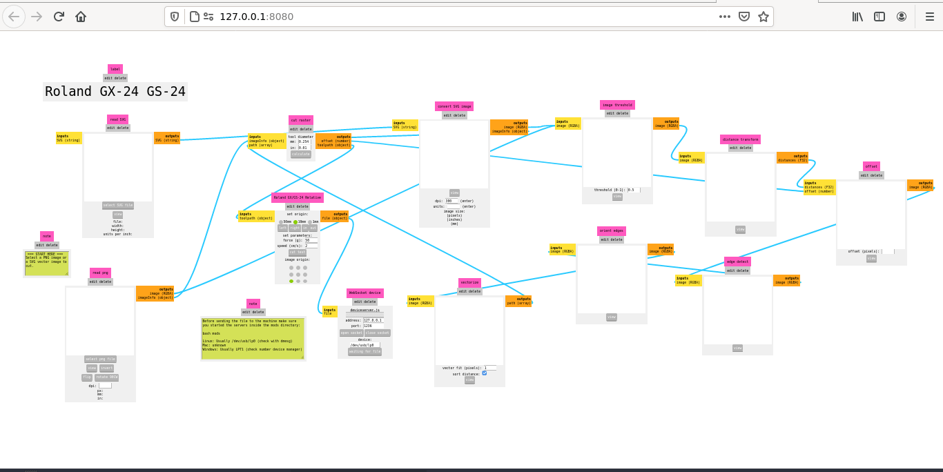
I tried to install the fab mods in to my pc.But didn't works out.while I spending time for the fab modes installation our mentor Mr.Rahul Rajan said that is not a part of this week of assignment.Then I skipped the part started to cutting the vinyl using FAB-Mods ,which already installed in the FAB LAB Computer I found the files and repository from here . Will try later with my own PC
week 3 assignment is to cut something on the vinyl cutter. And then design, laser cut, and document a parametric construction kit, accounting for the laser cutter kerf, which can be assembled in multiple ways, and for extra credit include elements that aren't flat
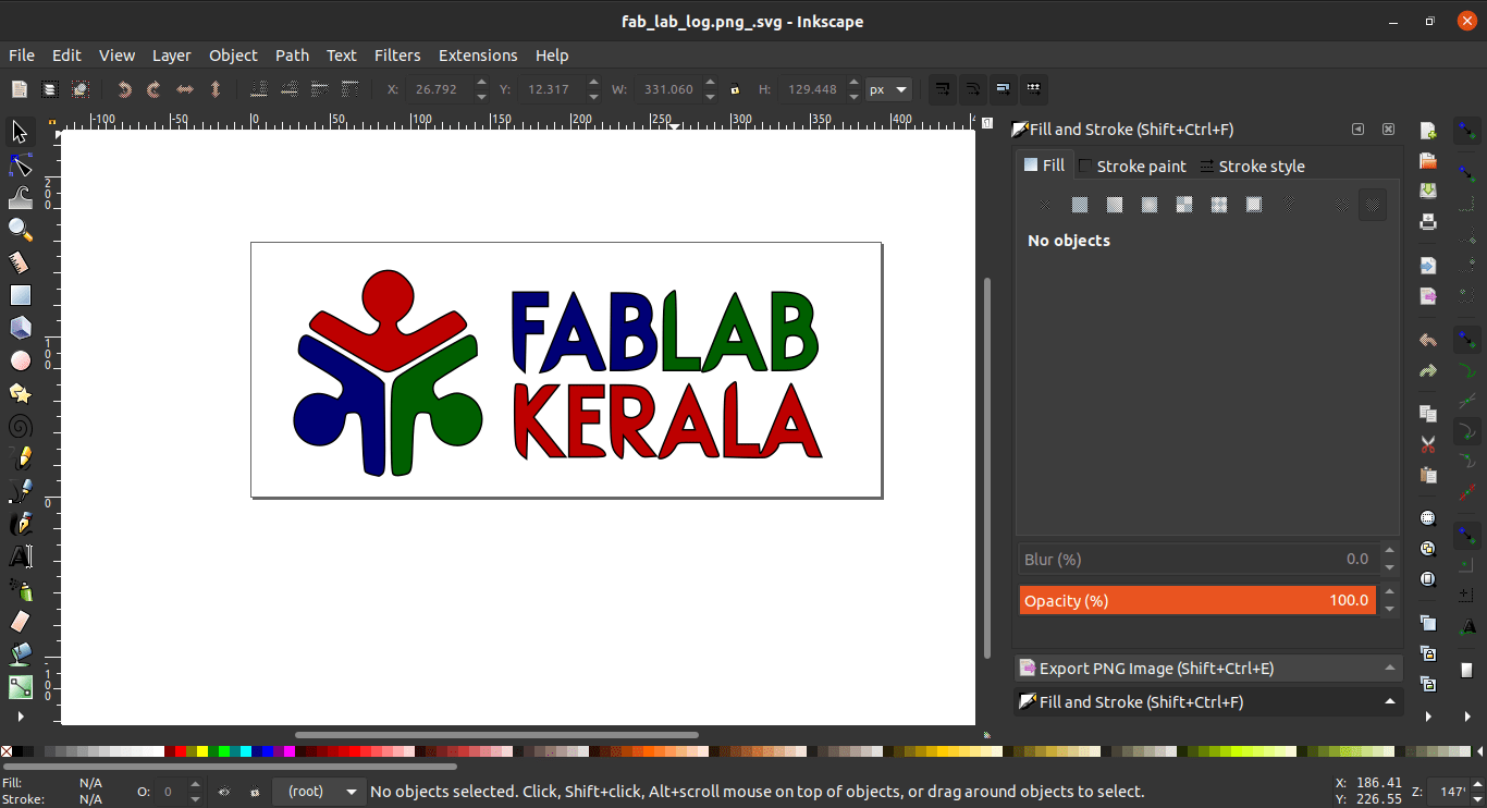
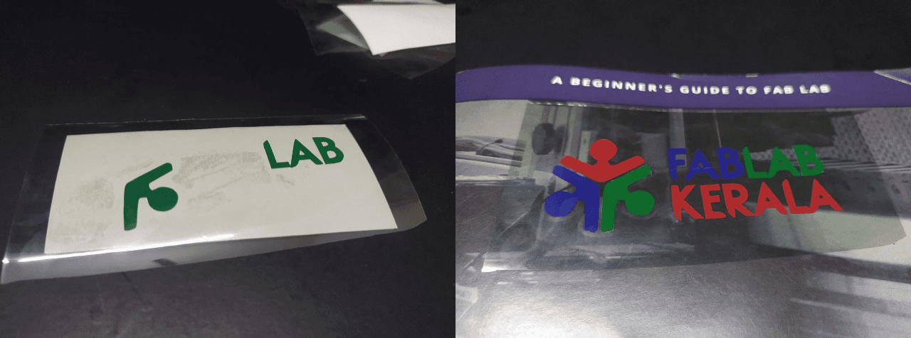
Logo Making in Inkscape
I decided to make a logo of FAB LAB Kerala and I got the PNG file Already. Then opened in Inkscape for giving size and tracing bitmap
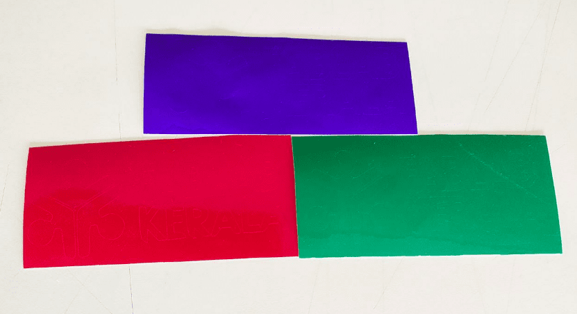
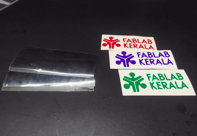
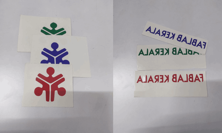
The logo contains 3 color Red,Green and Blue so I'm gonna cut the logo in 3 different color which is Red,Green and Blue vinyl all are in stock our FAB LAB
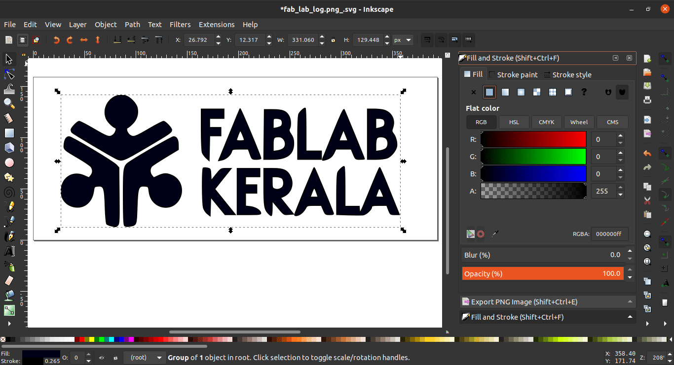
After tracing the Bitmap vector image I filled 'inside fill' with black color and given a size I wanted.It is important to give a dark fill in design.Other wise the machine will plot at the edges of the stroke line. Then saved as "fab_lab_logo.svg"
cutting in Roland
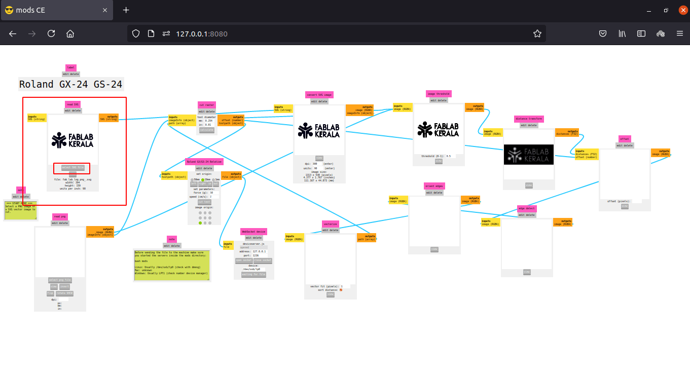
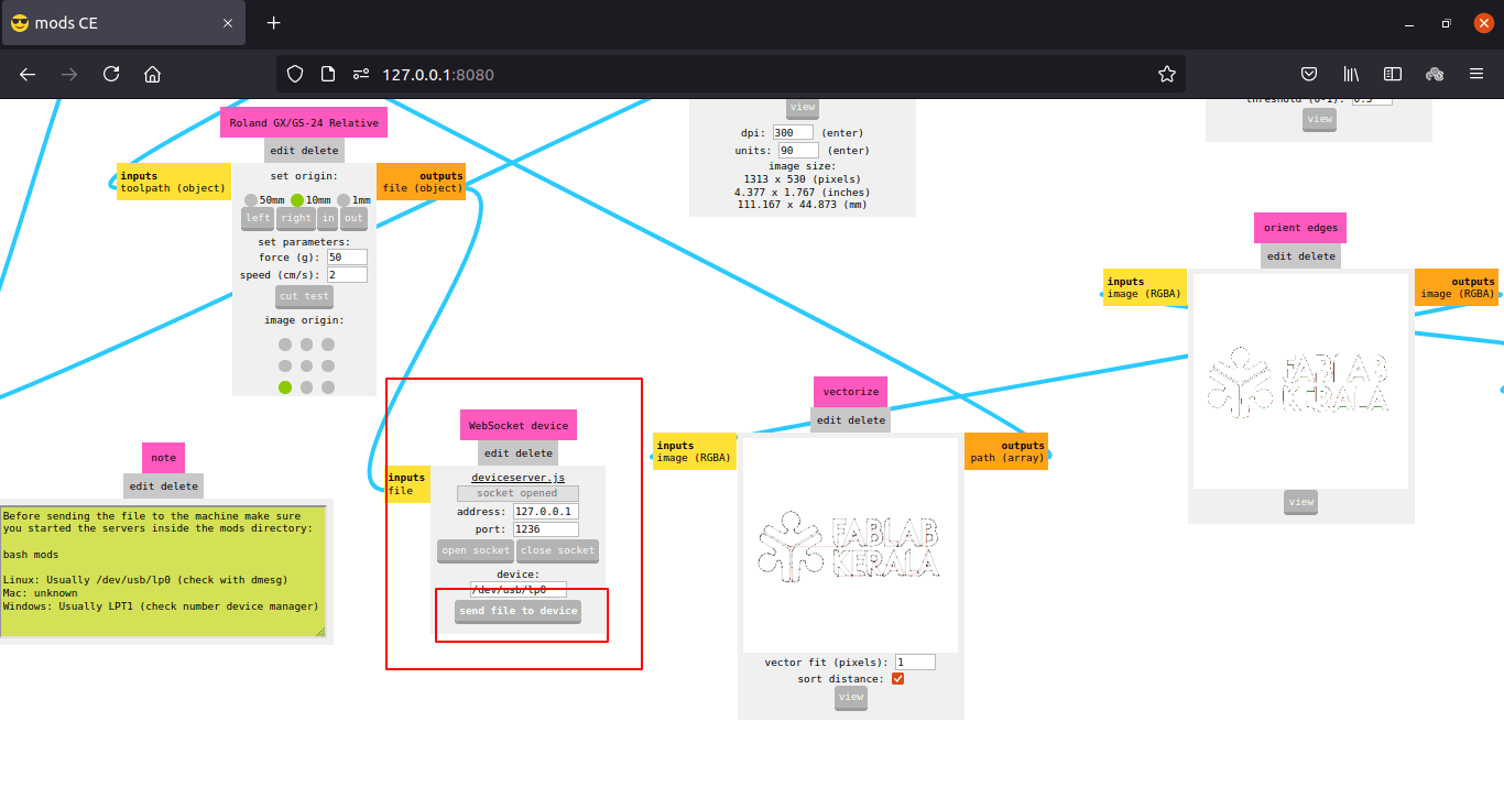
Now the SVG file is ready to cut so I opened the FAB Mods for Roland GX-24 and loaded the SVG file into it
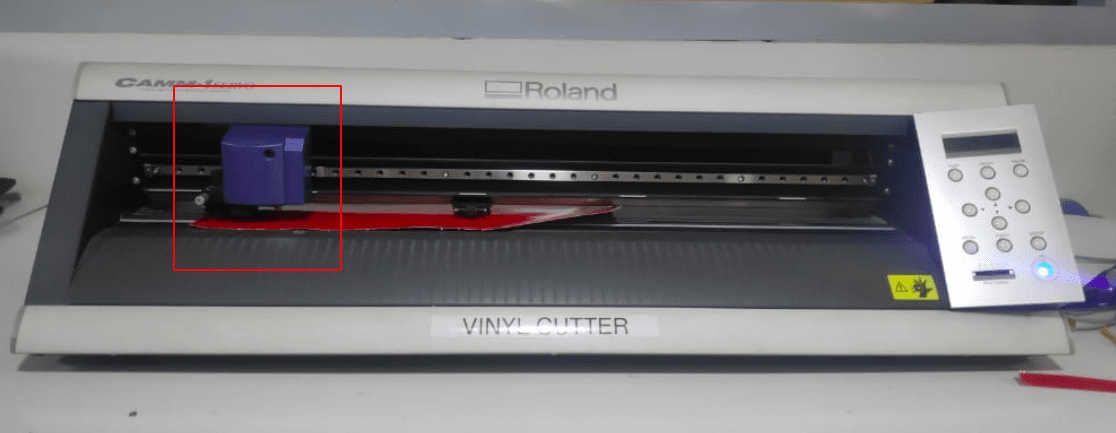
'png' file also supported but I chose vector file.Then I turned ON the Roland GX-24 and loaded a reel of Red Color vinyl
Then I aligned the vinyl with adjusting the roller guides in the white marked area. (the unmarked areas doesn't have grip to hold or push the vinyl ).
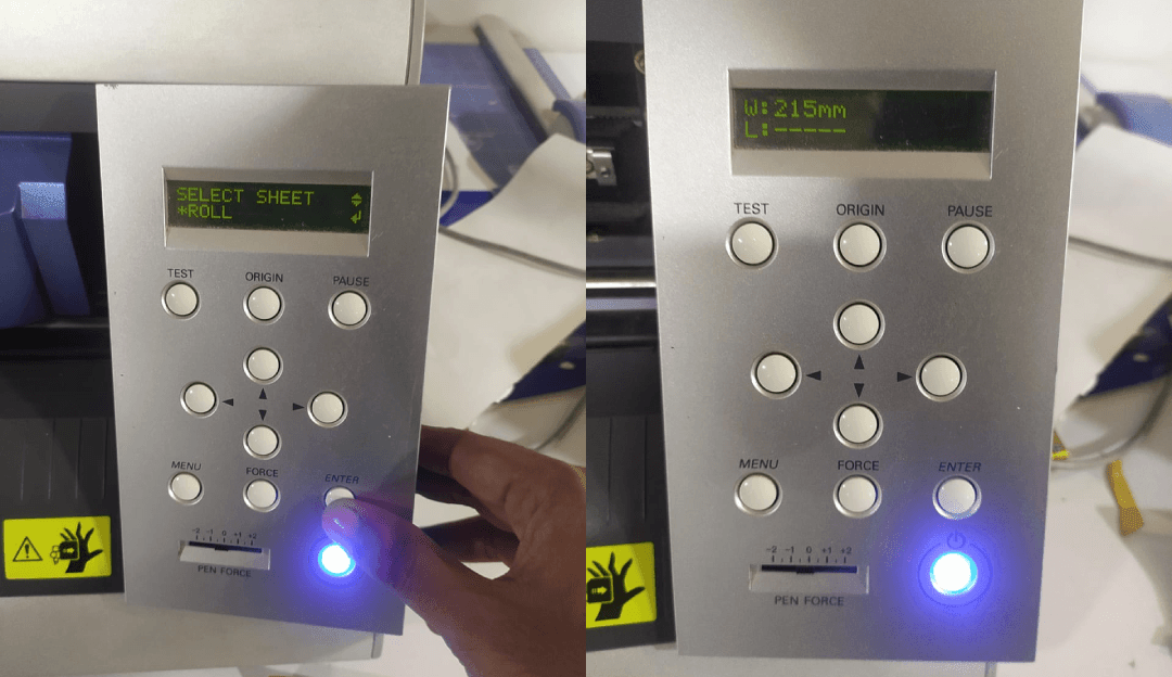
I selected role option menu because I'm using a role then it measured the length of the vinyl itself and displays dimensions.
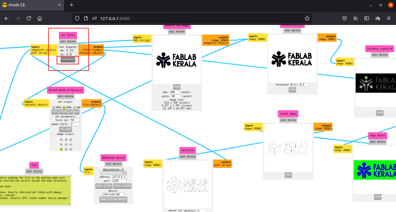
After loading the Vinyl roll I calculated the tool path in fab mods. The tool diameter already given by default
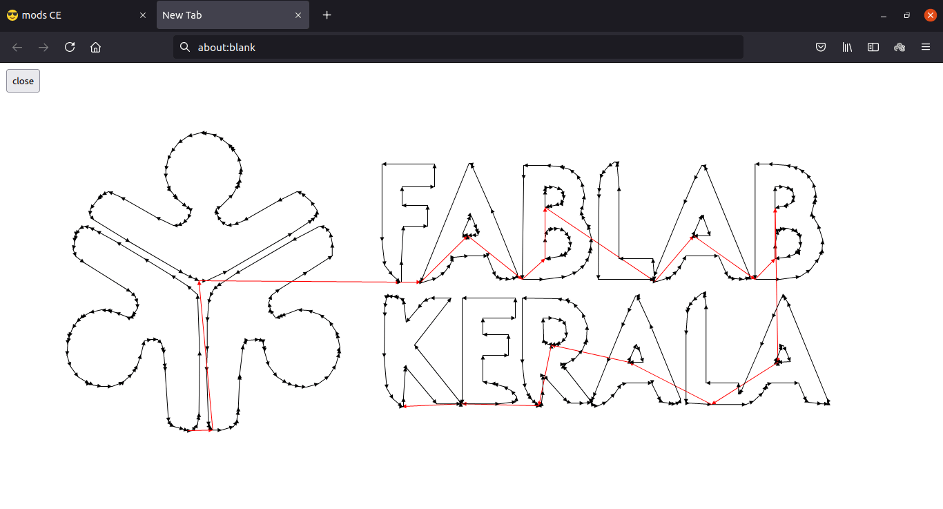
If we Click the view button in 'vectorize module' after calculation that will show the vinyl cutter tool path in New Tab
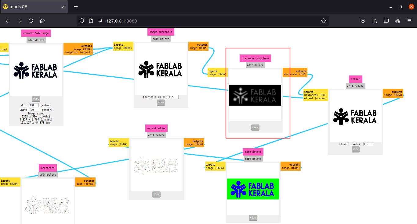
The other modules shows offset and how much detail we can get and etc...
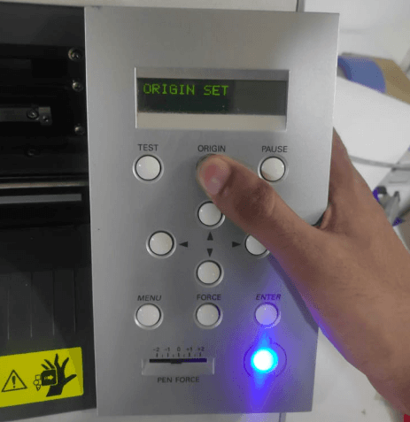
So to plot the logo I moved the cutting head to an end position and updated the origin position to the machine by long pressing origin set button.
Then I send the file to roland by clicking 'Send File to Device' button on mods
The cutting so fast it finished in 36 sec.You can see the cutting process in the video below which is 2X faster
After this I repeated the process for cutting Blue and Green vinyl and cuts out from the roll
Applying the vinyl sticker
I decided to stick it on a book face which I got from FAB LAB when joined the academy.Also need to align all the color in place to get the mixed result of the logo
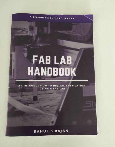
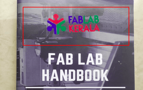
The book is about the fab machinery and nice hand book done by Rahul Rajan.
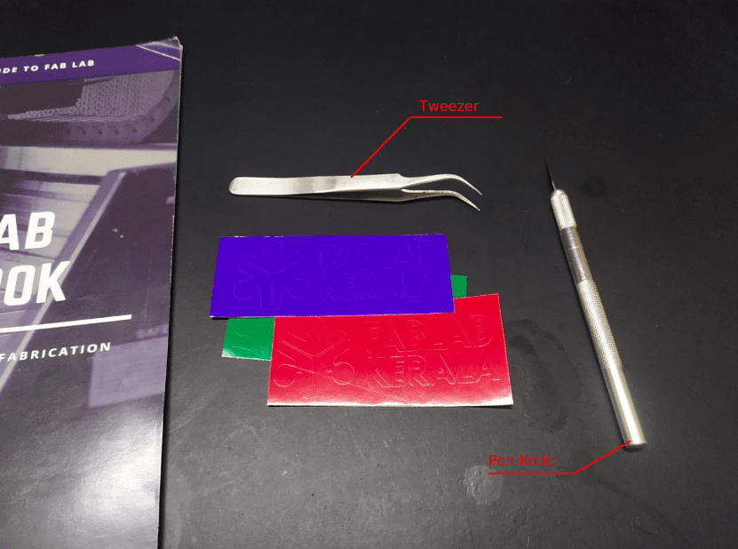
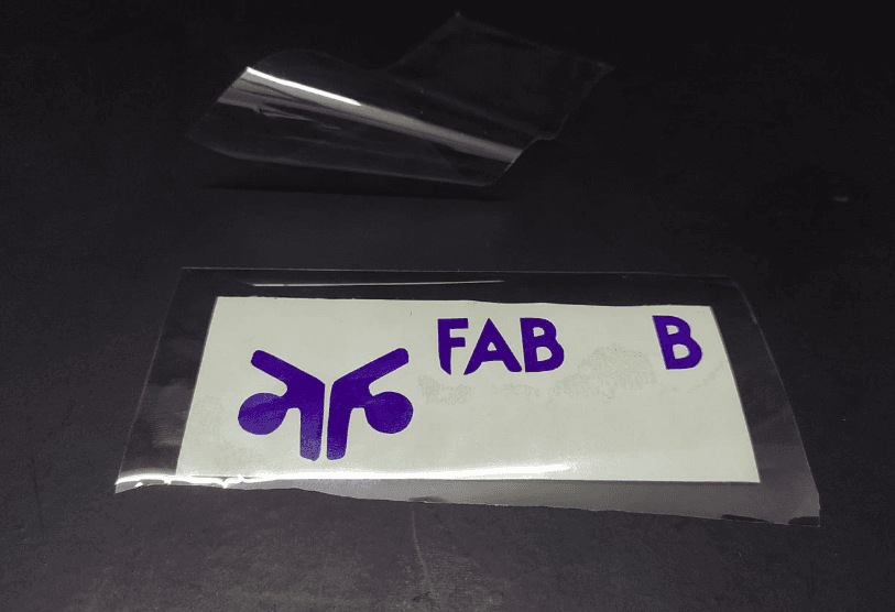
So first step is to remove the unwanted parts from the vinyl stickers I did with the help of tweezer and a Pen Knife.
All ready for applying. To stick stickers on surface a type tape is required which has less stickiness and Transparent.
Unfortunately in our fablab the Transparent sticker is ran out.So I got a pice of cooling stickers from local stores and cuts the sticker into 3 small rectangle piece as same as the vinyl.
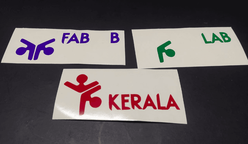
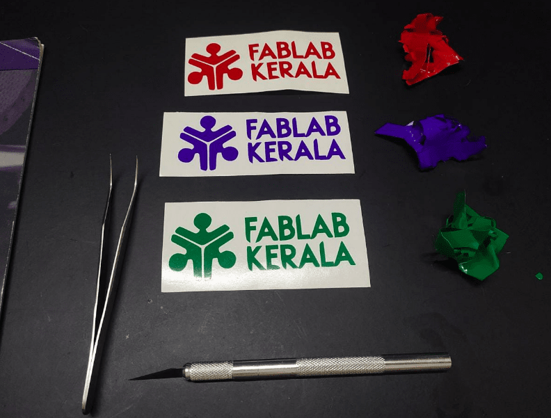
Then I peeled away unwanted letters and portions as per the logo also left something for common reference.
As a first step of applying vinyl I'm started with the blue sticker.pealed the cooling sticker and sticks over the blue sticker like in the picture.
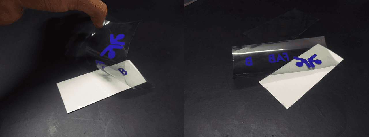
Then I pealed the cooling with vinyl.it came out very easily and without any misalignments.
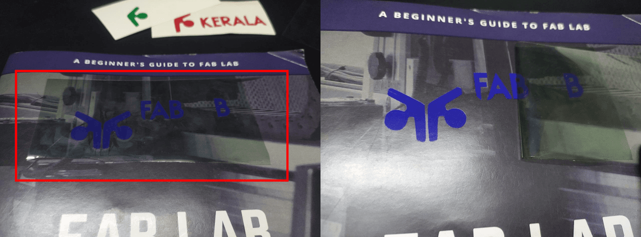
And then I sticked on the top of the Hand book and applied a wiped pressure all over.After I pealed the cooling sticker away so the vinyl blue log are in place.
Then I marked the logo's unwanted portion which I left for aligning and removed the blue portion.
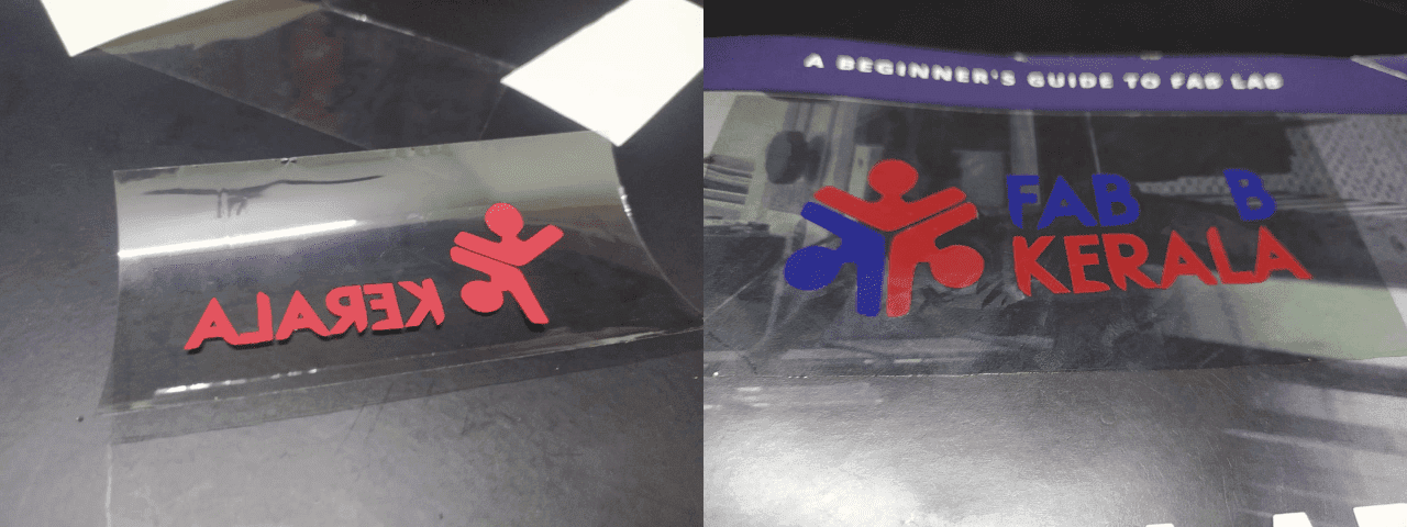
I did with the same process with red vinyl following the blue
This time I'm also marked and removed the letter B with the logo portion.
And the I applied the green vinyl sticker carefully and pealed away the cooling sticker.
The results is great have some misalignments to te book but its Ok I love it!.
Back to FAB MODs
After the vinal I tried to install the fab mods agin here I'm explaining how I did it step by step.
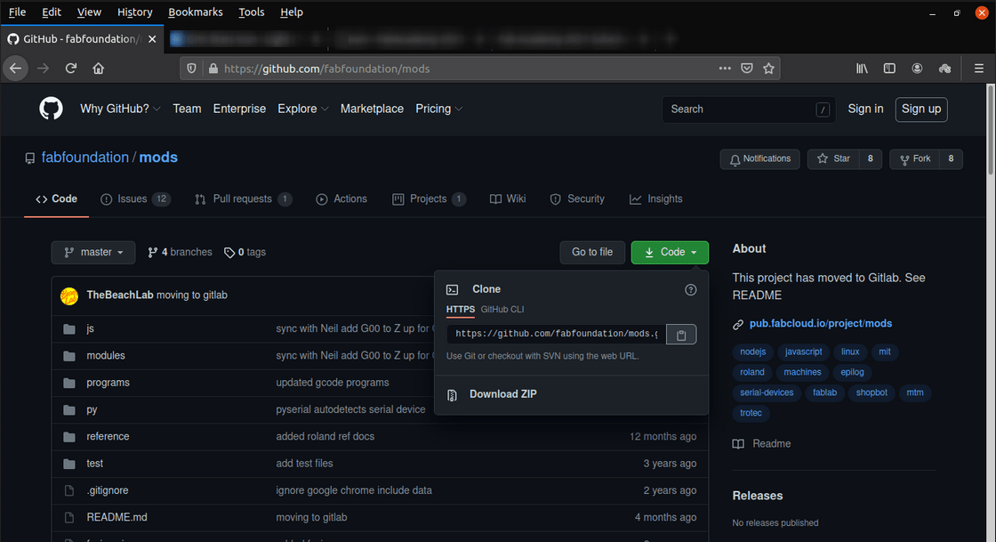
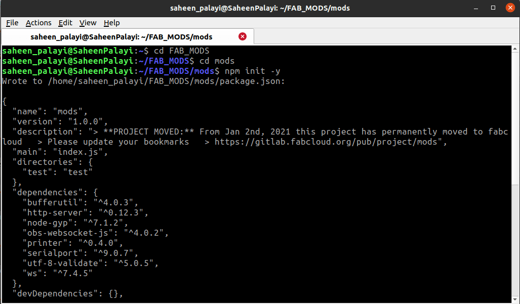
I copied the Cloning link from the Mods GitHub repository
git clone https://github.com/fabfoundation/mods.gitIn terminal I created a directory called 'FAB_MODS' then I cloned the repository into the folder using above git clone command
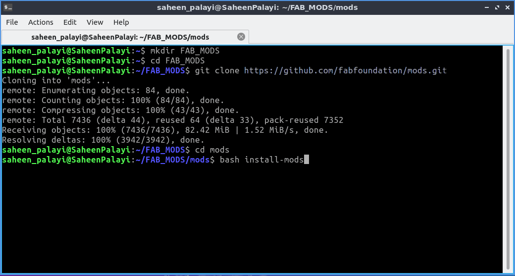
After cloning I changed the terminal directory into 'mods' then I installed the mods by running the command found on the github documentation
bash install-mods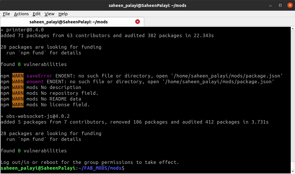
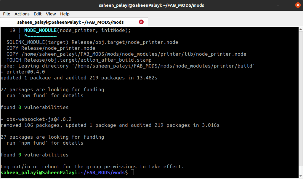
After the installation it shows some package.json missing error.but any way I decided to run the fab modes
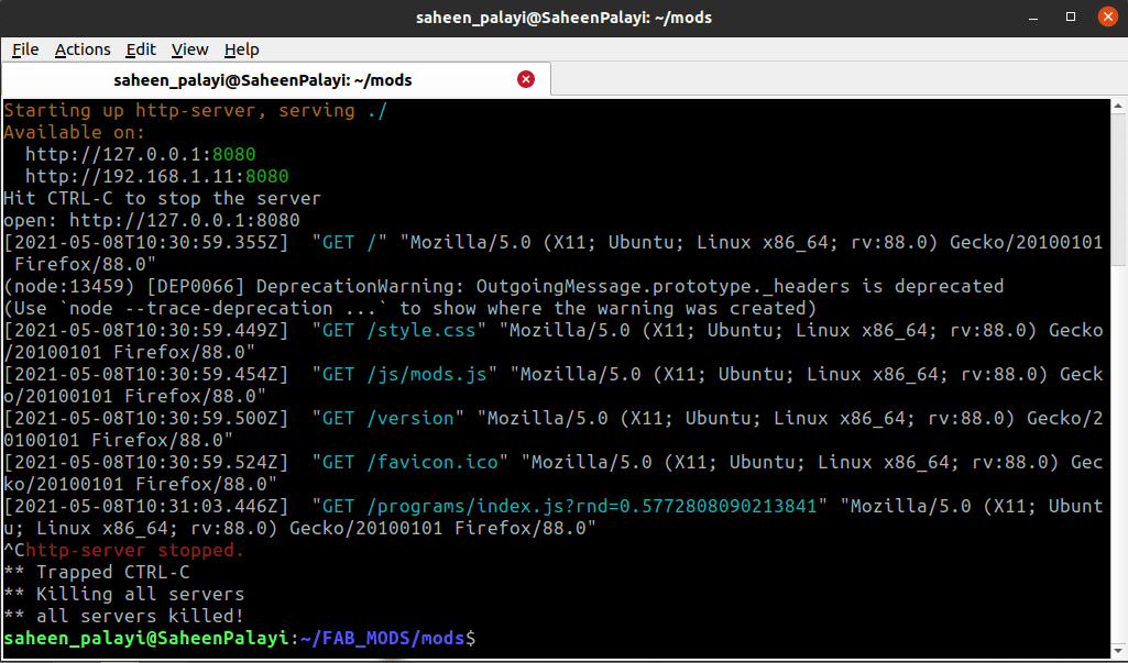
bash modsby running the above command into the terminal it opens a new webpage window on my Browser
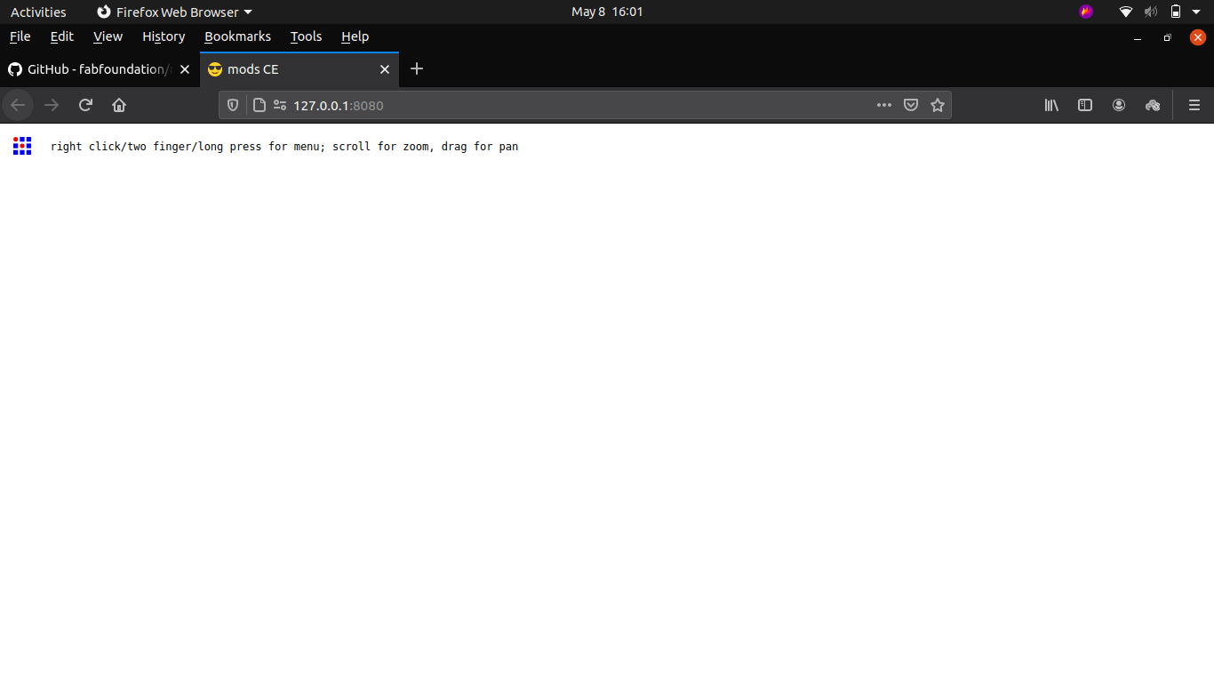
This is how I installed the fab mods we can exit from the server anytime by pressing 'Ctrl+C' in the terminal
But I face problem while using this with the roland_GX-24 vinal cutter it doesn't connecting properly I checked the installation process and find out the missing error of the 'package.json' is the problem
The fab mods works like a server app in my pc so it runs on Node.js server program it need npm to install and run.so in order to get the 'package.json' file I used this below command in terminal
npm init -yThis command creates a package.json file in the folder
After this I run the installation of mods command again and this time installation finished with out any error
This time It works well with the vinyl cutter finally I have my own FAB mods in my PC!. But actually this solution dose not solves the connecting problem That I had
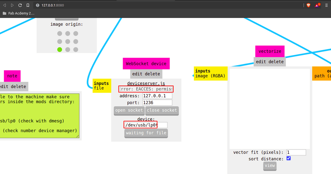
I noticed the Port selection of the mods Roland's module It was lp0 by default may be my pc has different port so i ran the command below to see all ports which connected to the pc.
dmesg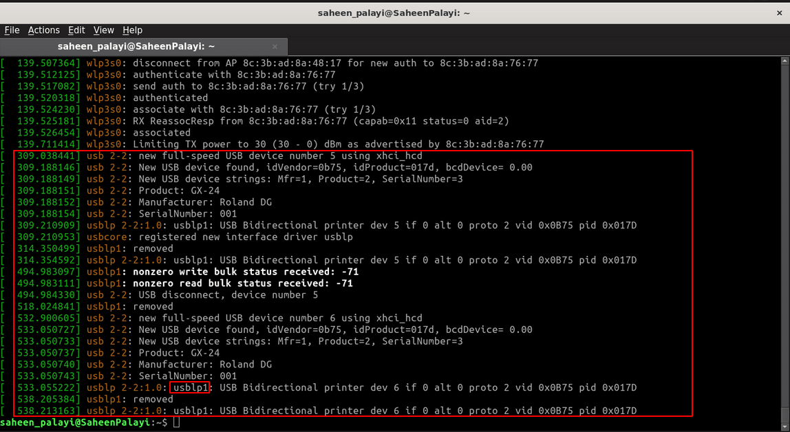
After I give the comand in the terminal that listed the USB device detials which is connected to the PC and it shows that The Port was actually named 'uslpb1' so I changed the '/dev/usb/lp0' to '/dev/usb/lp1' in-order to made it work
Logo on A T shirt
During the fab Wednesdays session I heard that we can embed Vinyl stickers on a t shirt via heat transfer. So I got inspired by the process and decided to try my own found an tutorial written by Adrian Torres during his Fab Academy.check out his Week3
Actually the method is pretty simple, First of all we need some materials and equipments specially used for this process.Vinyl sheet isn't the same as we are using in the lab. Specially made vinyl sheets available in the market.
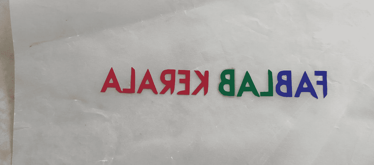
So I cuts out our Fab LAB Kerala's logo and the name same as before but the dimensions are different . for the dimension I was taken reference from an old shirt of mine which I got from community hackathon. Note that the name is in mirrored because we are not sticking the on the shirt ,The other side stick with the shirt .
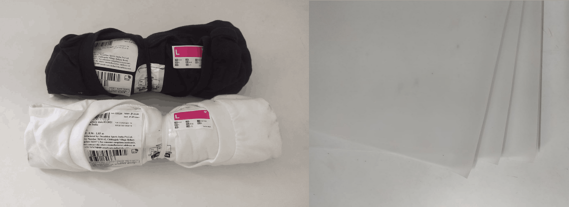
I bought two low cost basic T-shirt from Decathalon . its only cost just 129 Indian Rupees (near 2 US Dollar) per one shirt.Also bought transparent tracing paper which is also capable of handling the heat and the transparency helps to see the vinyl cut align. We can grab them from the market its available in std sizes like A4,A3..etc..
Then I applied the logo in colored order on the tracing paper like I did before and followed same method to arrange in position
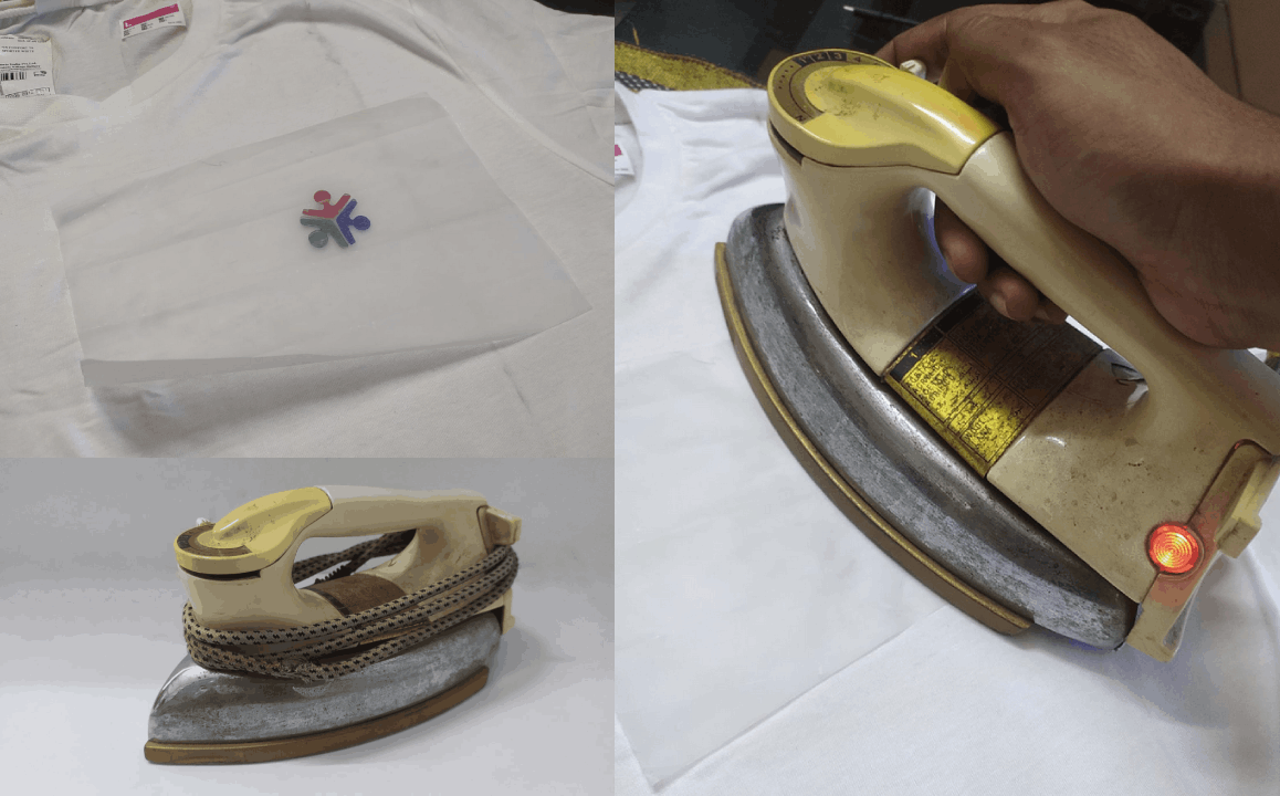
After that I placed the tracing paper on the t shirt in position which is the logo vinyl face down. Then heated on top with pressure by an ordinary Iron box from my home. This Iron box is an older technology and it's weigher than new types of iron boxes also heats well.
Then I pealed off the tracing paper from the T-shirt after made sure the logo sticked on the shirt well.That went well some sticky gum feel on the logo but I thing that can be remove in washing process.
Then I also tried to stick the name on the top back of the shirt but that ain't went well very hard to stick smaller detailed objects without correct equipments and vinyl.

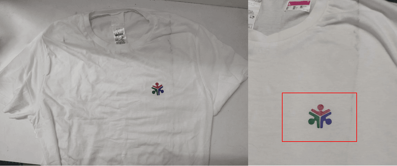
Here is the hero shot of I'm wearing the shirt in a mirrored view . The logo was mirrored forgot to arrange in correct way while arranging on the tracing paper. Also washed the shirt before wearing because u can see in the previous picture some dust line on the shirt.The vinyl logo was really sticked well even after I wash I think it gonna last for 100+ wash and use.
I really enjoyed learning the T shirt vinyl printing.. with available facilities and material whi is also helps me to understand the process.I really recommended to all fabians to try out this to create your own brand shirts in low cost. also checkout above mentioned documentation from Adrian Torres for more accurate method of T-shirt vinyl printing.
Press-Fit Construction Kit
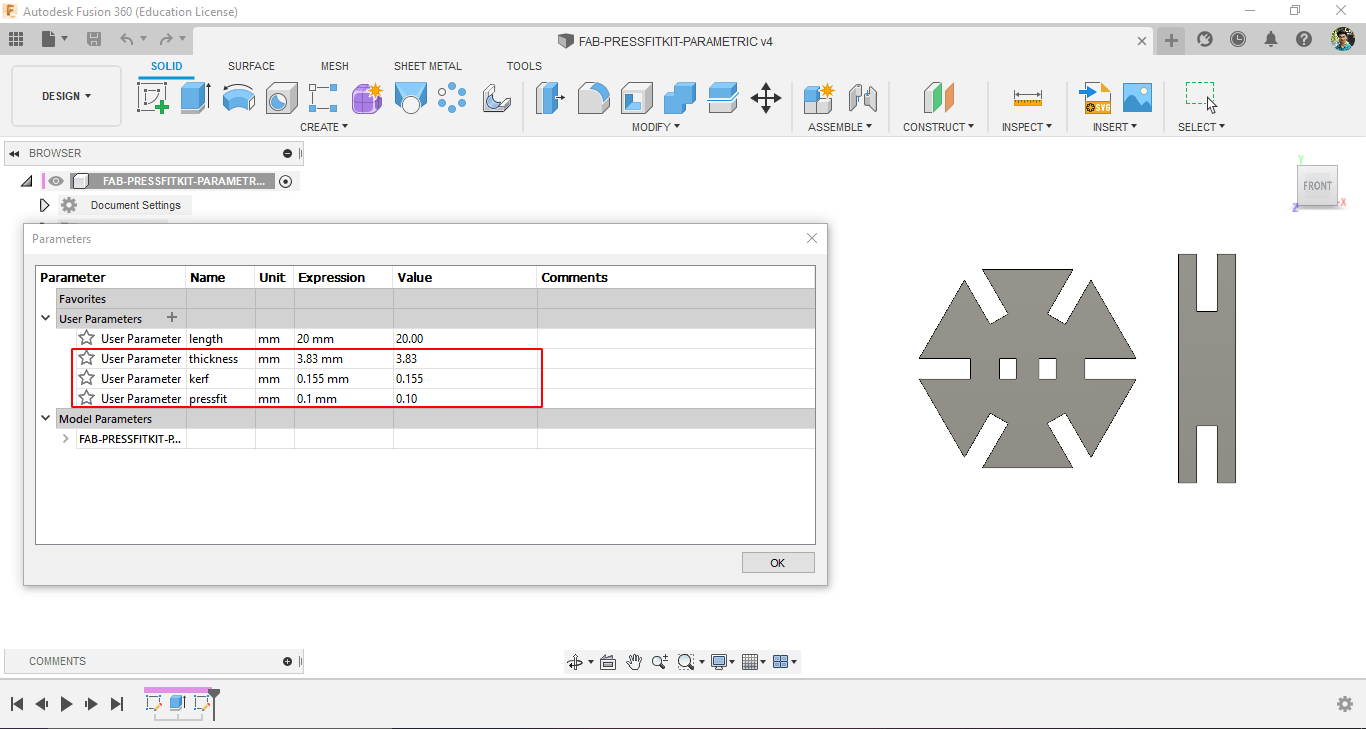
Based on the Data we collected during the group assignment I started to design my own press fit construction kit in Autodesk Fusion 360
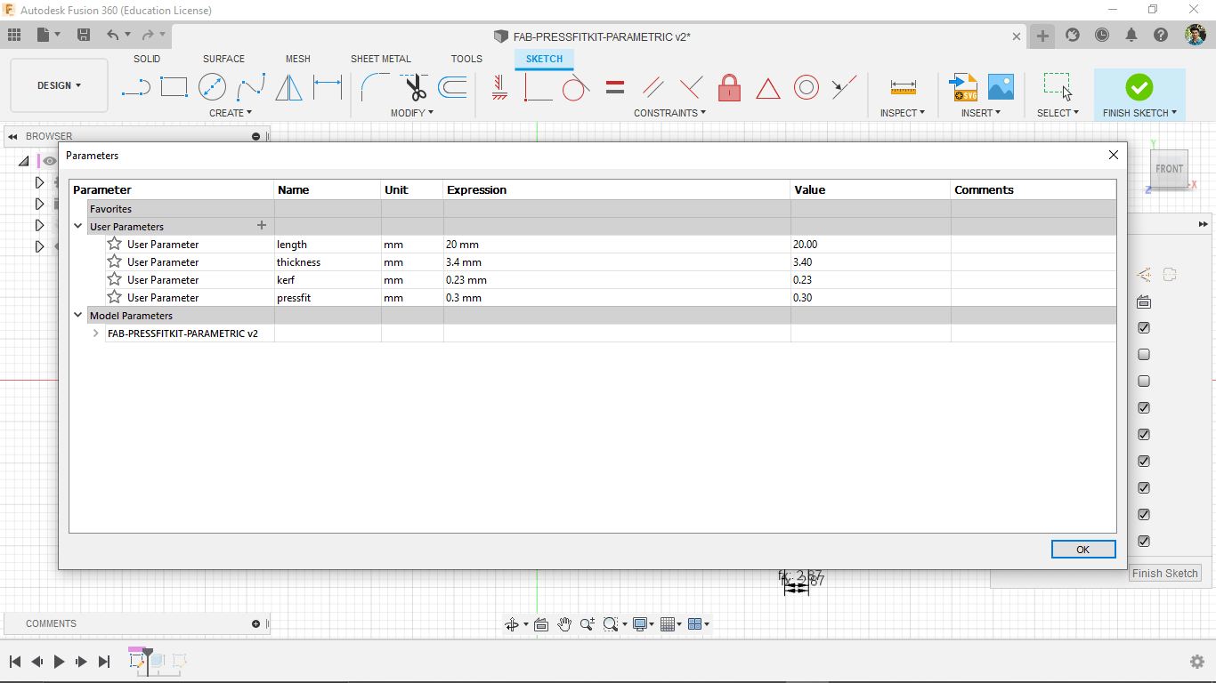
I created some parameters in fusion like length,thickness,kerf and pressfit clearance and I added the values which we got from the press fit, Kerf testing
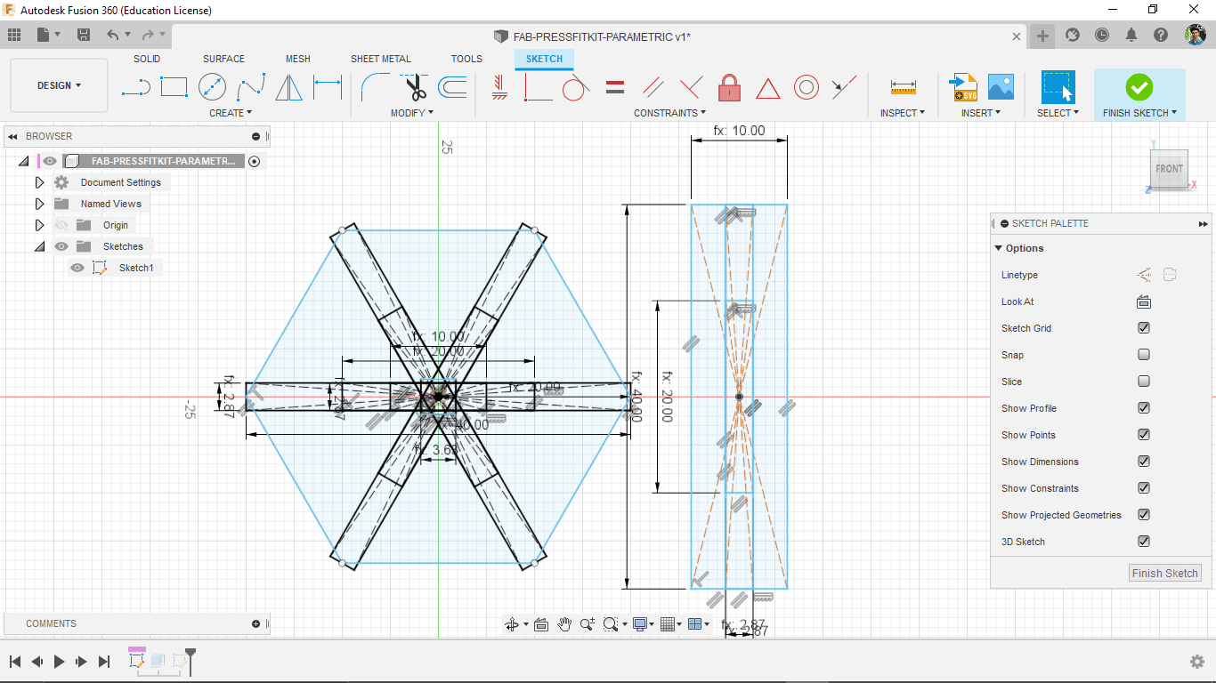
Then created a sketch of a hexagonal shape and a rectangle stick shape using the parameters.
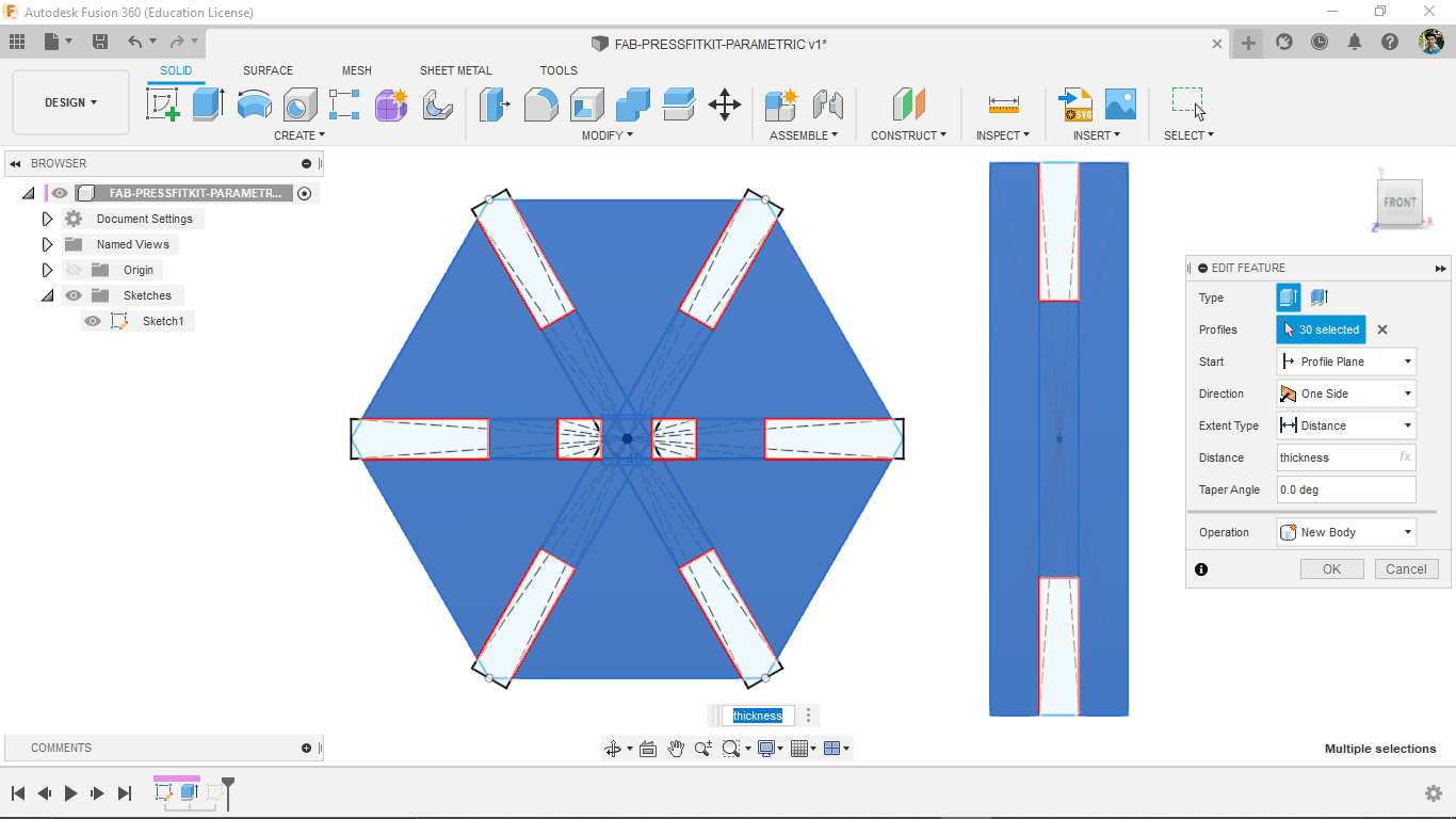
After selected sketch and extrude to the thickness that I given in parameters.
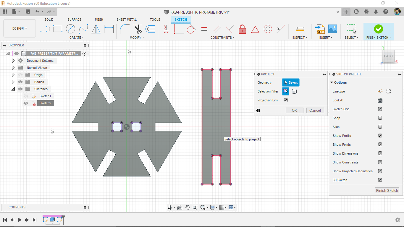
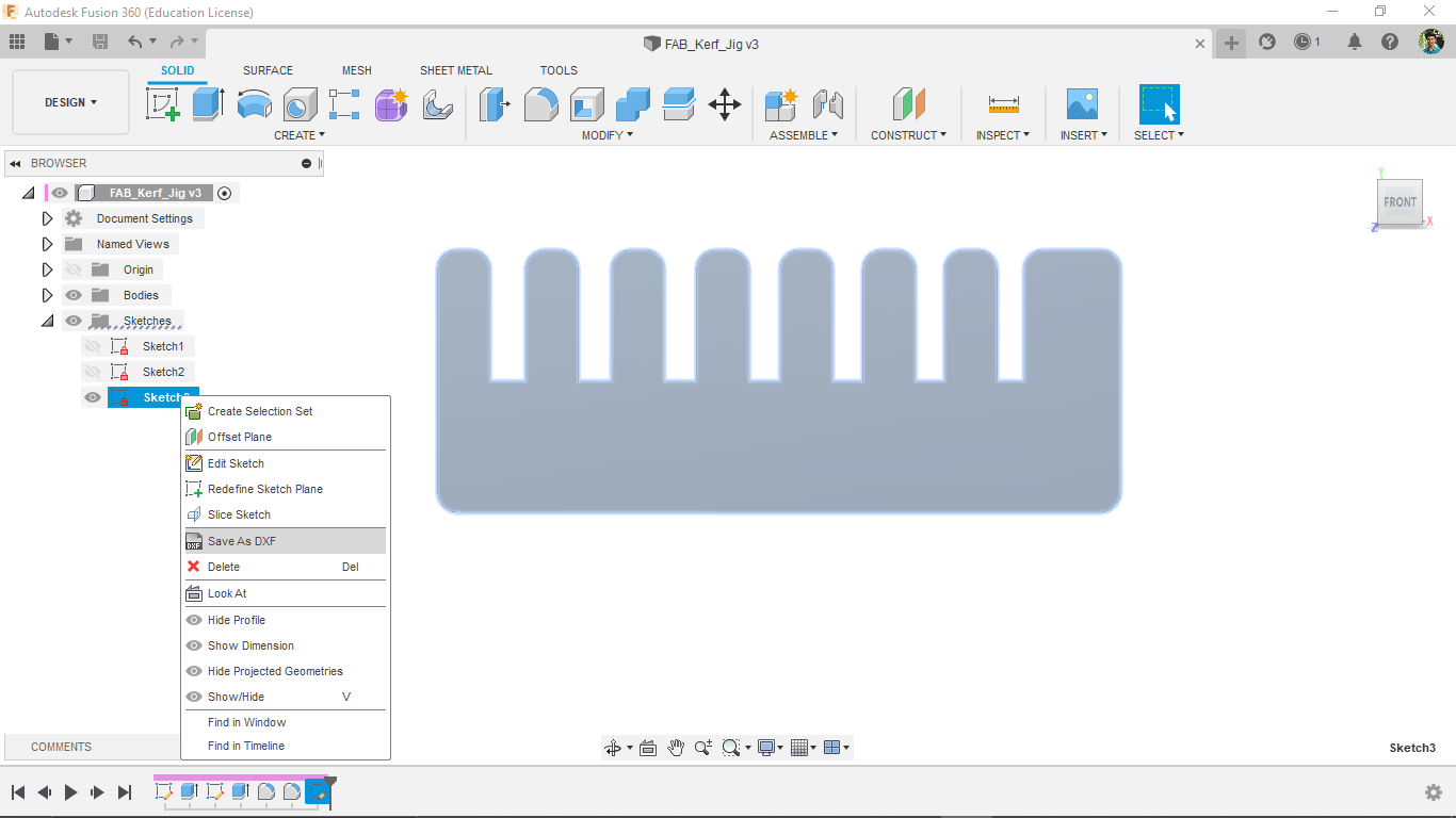
For saving The 2D vector created a new sketch on the hexagonal shape and projected the rectangle shape in to the sketch then fished the sketch.
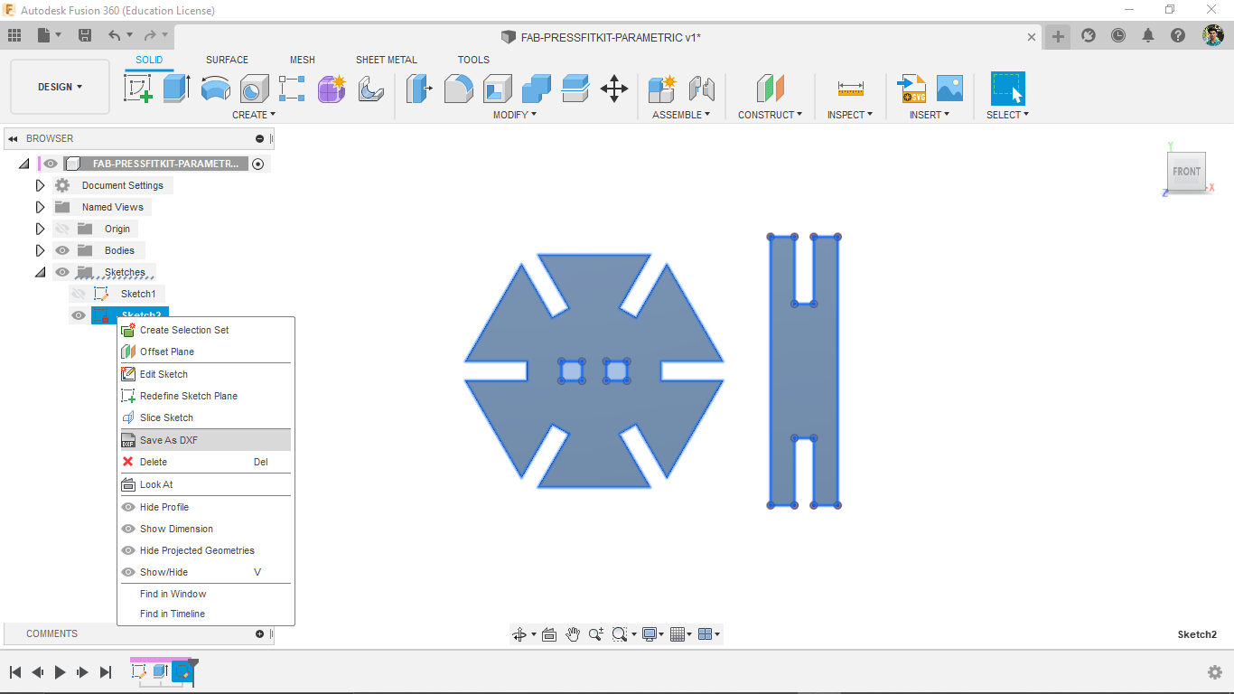
In the sketch directory on left side the newly created sketch shows, by right clicking on it and selecting the 'Save AS DXF' option and saved in to my PC.
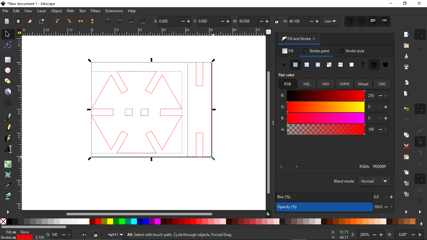
Then I opened the saved DXF file in the Inkscape and changed the stroke color to Red for cutting and send to Trotec software.
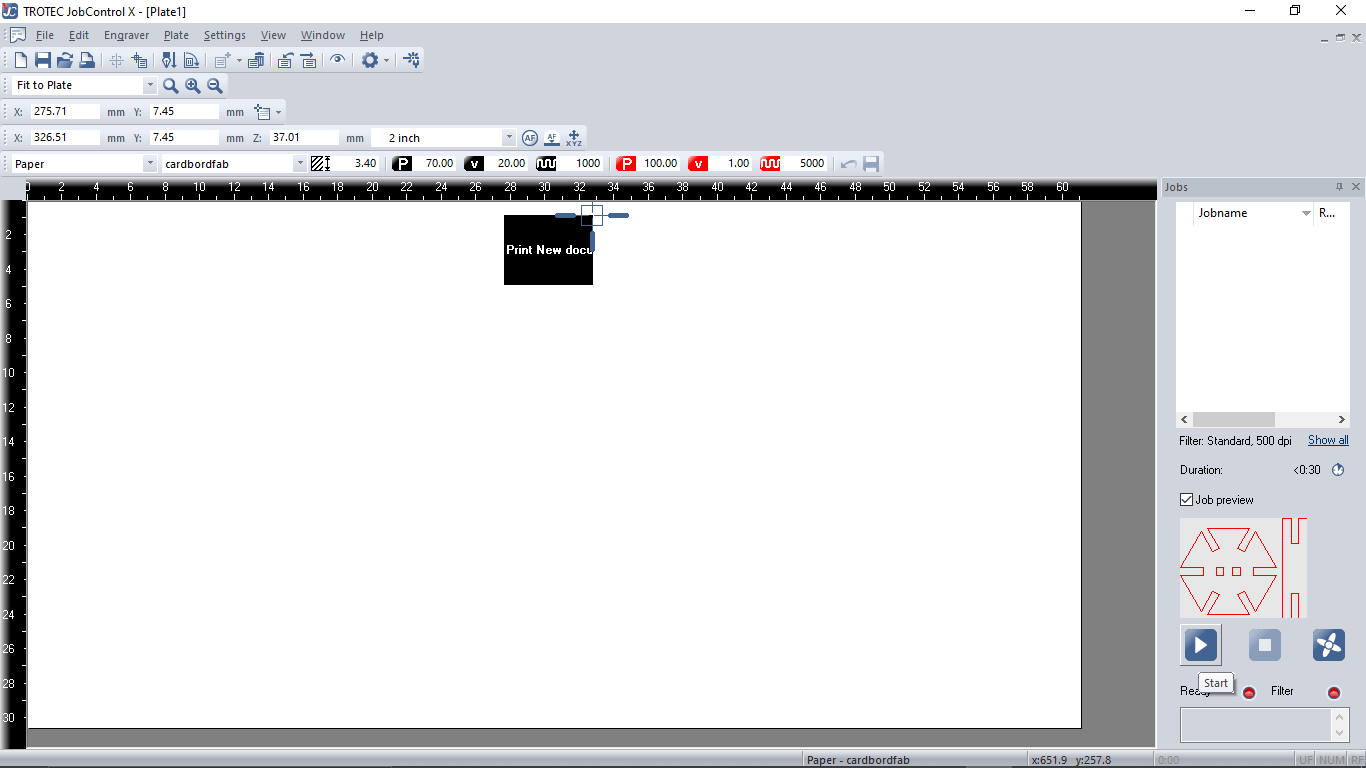
Firstly only cutting one set for Test so selected the cutting settings for 3.4 mm cardboard and cut it out.
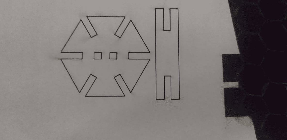
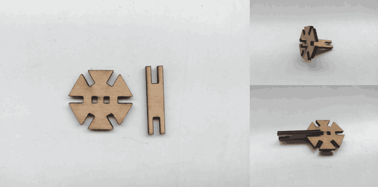
It cuts beautifully then I take out the parts and try to fit them together.

Fits well in both ways good press-fit all.Then I decided to try the Parametric capabilities by cutting in different thick Material
I changes the parameters in the design for cutting in wood based on the detials collected during group assignment for checking parametric capabilities of the design. Then exported to dxf
Then I cut out the parts and checked for the joints and press fit. All good for mass production! But Cant do in Wood because it's not that cheap to use here.
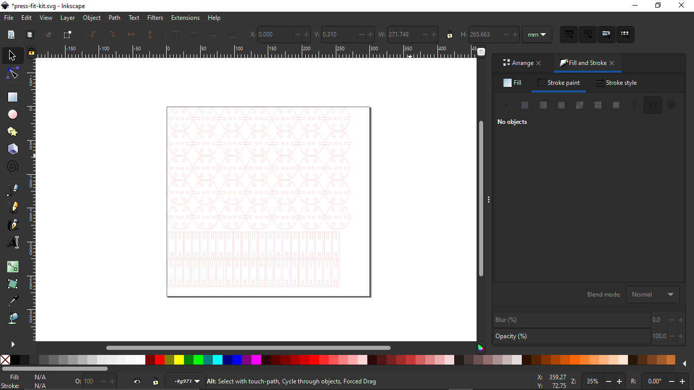
I nested the parts as many as I need in a 1 square feet (approximately) document in Inkscape and stroke set to red and made it thin line (0.1 mm).
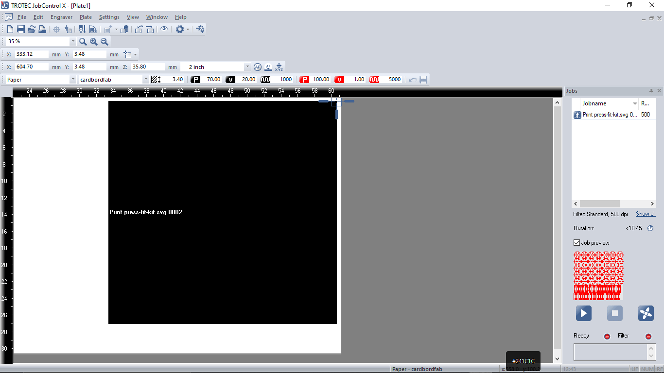
Then loaded in to trotec software and set the origin position and cutting setups then hits play button.
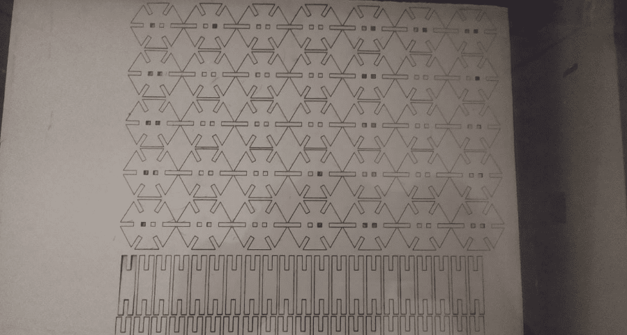
Cutting the cardboard is not accurate if it has bends so in that cases we should make it flat as possible and also recommended to adjust the velocity of cutting settings from 1 to 0.9 or 0.8.
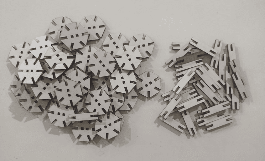
So all set to build!. I've tried 2-3 times to collect all of these components Because of the bends in card boards. Then starts to build something out of it
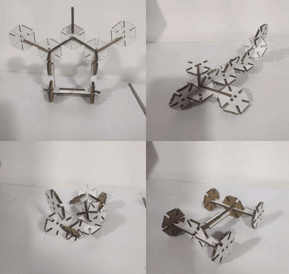
I constructed more than one or two things out of it. Built a robotic shape , a plane , a snake and a vehicle chassis I did not have any idea That I can build and end up with these thing when I started to build with the kit
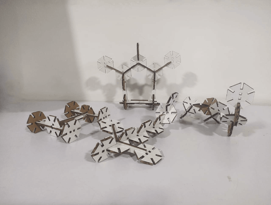
So theses the all the thing I built this week its very Interesting! to play with the construction Kit
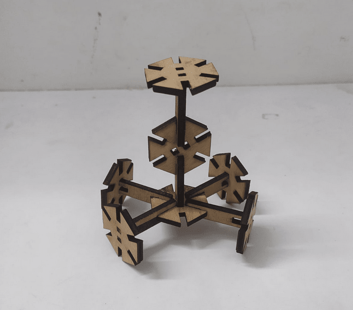
This wooden structure was a bonus for me I've collected older cut pice from the lab and did cut the parts on it one by one depends the area available on the pice. it's look nice!
Resources
References
- Fab Academy Computer-Controlled Cutting classes
- Trotec Speedy Laser Engraving Machine
- Roland GX-24 Vinyl Cutter
- Laser Cutting Process
- FAB MODS GitHub
- Adrian Torres's week03
Downloads
- kerf test
- Press-Fit jig Files
- Vinyl cut Files
- Press-Fit construction kit Files