Understand the working principles behind various input devices
Desgin a board with an added input device
Tools:
I couldn't reach the lab for Input Devices week. I went back to Hyderabad, and was stuck there due to Covid uncertanities. Therefore, I've decided to complete the design part, and study the theoretical principles of various input devices.
After going through Neil's lecture twice, I have started watching a whole lot of YT videos on Oscilloscopes: here, here. In the process, I have even come across something very cool called 'Oscilloscope Music' - here
In the Embedded Programming week, I have played around with in-built capacative touch sensors on ESP32S-NodeMCU. Here is the relevant video:
In the same week, you can see me trying to transmit light morse code using inbuilt smartphone light sensor: here
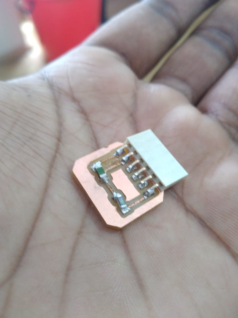
The step-response is a sensor that is made with two sheets of copper, separated from each other by a porous insulating material. It can be used to calculate the value of force, weight, resistance ... I am following Matt Blackshaw's documentation: here
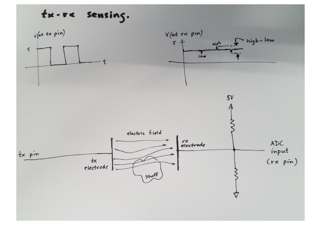
So, this is my understanding of how this works: High and Low voltages are transmitted in a periodic manner from the tx pin, and the resultant voltage is measured from the rx pin. The difference between the resultant voltage in high and low states over a period of time will give us a number, and this number changes based on the medium, and proximity betweent the electrodes. Thus, we can detect the touch, and many other things.
Here's how it works, according to Robert Hart: TX_RX Sensors
transmit (tx) pin is made alternately high (5V or 3.3V) and low (0V). Note that the figures show the number for 5V boards. For 3V boards (like the ATSAM-based Adafruit boards) the highes voltgae is 3.3V.
This charges and discharges the tx electrode.
On the rx electrode there is a small 'blip' up or down as the tx pin toggles.
These blips are measured by the Arduino analog input (ADC), and "low" subracted from "high" (see figure).
This result varies depending on how closely the two plates are coupled by the electric field. It increases as the distance decreases and also changes with the amount of overlap and the material between the plates.
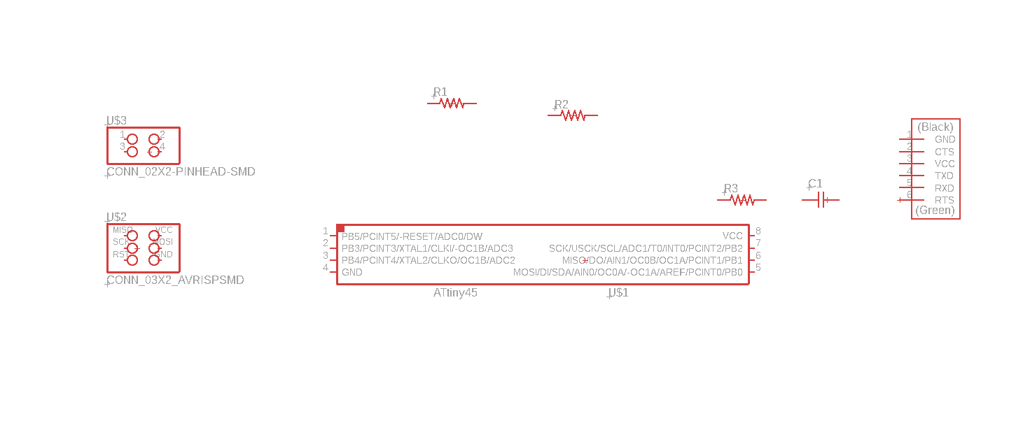
I have opened up Eagle, and started making the schematic.
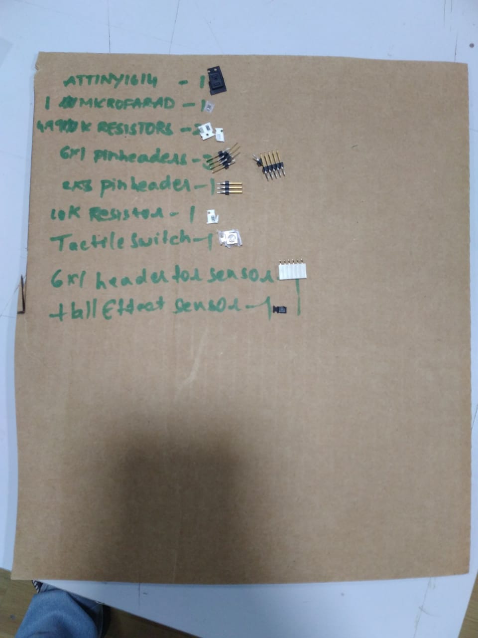
Components:
ATTiny45
FTDI
2 X 3 ISP Header
2 X 2 Flat Connector
3 Resistors
1 Capacitor
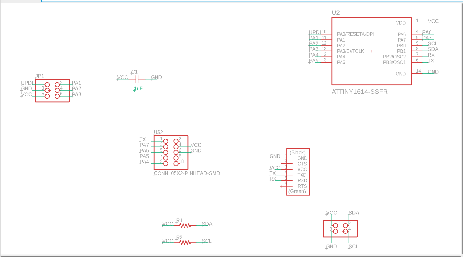
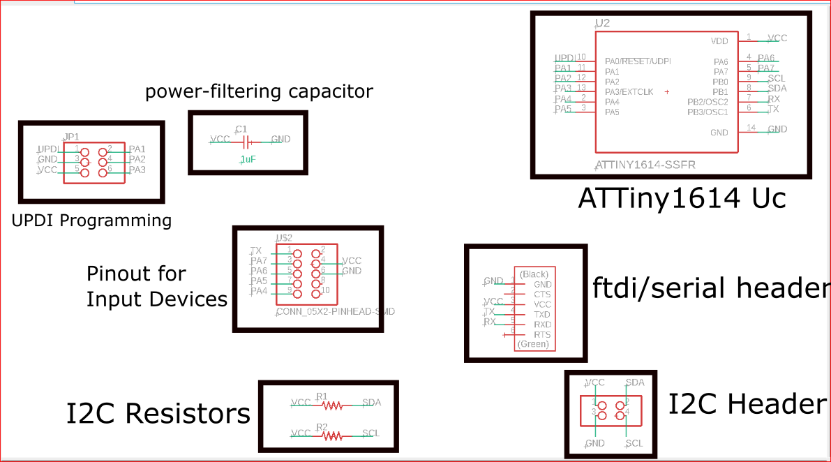
The schematic:
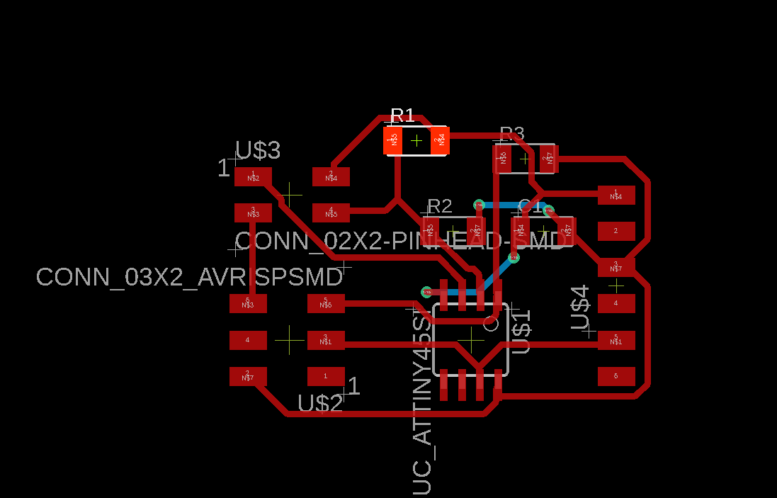
The first iteration:
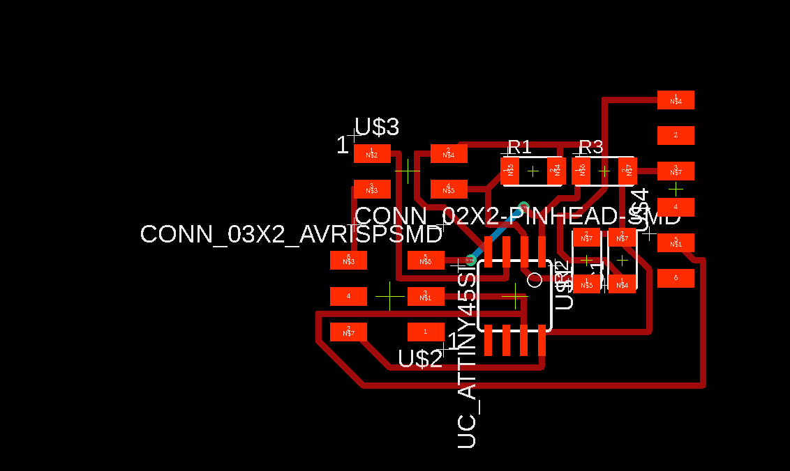
The second iteration:
Next, I will fabricate the PCB, and use two copper strips to build the sensor, then I will communicate the result over serial, and detect touch.
Code I will be using:
                //tx_rx03  Robert Hart Mar 2019.
//https://roberthart56.github.io/SCFAB/SC_lab/Sensors/tx_rx_sensors/index.html

//Modified by Adrián Torres Omaña
//Fab Academy 2021
//Step Response TX, RX
//Adrianino
//ATtiny1614

//  Program to use transmit-receive across space between two conductors.
//  One conductor attached to digital pin, another to analog pin.
//
//  This program has a function "tx_rx() which returns the value in a long integer.
//
//  Optionally, two resistors (1 MOhm or greater) can be placed between 5V and GND, with
//  the signal connected between them so that the steady-state voltage is 2.5 Volts.
//
//  Signal varies with electric field coupling between conductors, and can
//  be used to measure many things related to position, overlap, and intervening material
//  between the two conductors.
//


long result;   //variable for the result of the tx_rx measurement.
int analog_pin = 1; //  PA5 of the ATtiny1614
int tx_pin = 2;  //     PA6 of the ATtiny1614
void setup() {
pinMode(tx_pin,OUTPUT);      //Pin 2 provides the voltage step
Serial.begin(115200);
}


long tx_rx(){         //Function to execute rx_tx algorithm and return a value
                      //that depends on coupling of two electrodes.
                      //Value returned is a long integer.
  int read_high;
  int read_low;
  int diff;
  long int sum;
  int N_samples = 100;    //Number of samples to take.  Larger number slows it down, but reduces scatter.

  sum = 0;

  for (int i = 0; i < N_samples; i++){
   digitalWrite(tx_pin,HIGH);              //Step the voltage high on conductor 1.
   read_high = analogRead(analog_pin);        //Measure response of conductor 2.
   delayMicroseconds(100);            //Delay to reach steady state.
   digitalWrite(tx_pin,LOW);               //Step the voltage to zero on conductor 1.
   read_low = analogRead(analog_pin);         //Measure response of conductor 2.
   diff = read_high - read_low;       //desired answer is the difference between high and low.
 sum += diff;                       //Sums up N_samples of these measurements.
 }
  return sum;
}                         //End of tx_rx function.


void loop() {

result = tx_rx();
result = map(result, 8000, 11000, 0, 1024);  //I recommend mapping the values of the two copper plates, it will depend on their size
Serial.println(result);
delay(100);
}
After Reaching The Lab:
Schematic :
Reasoning:
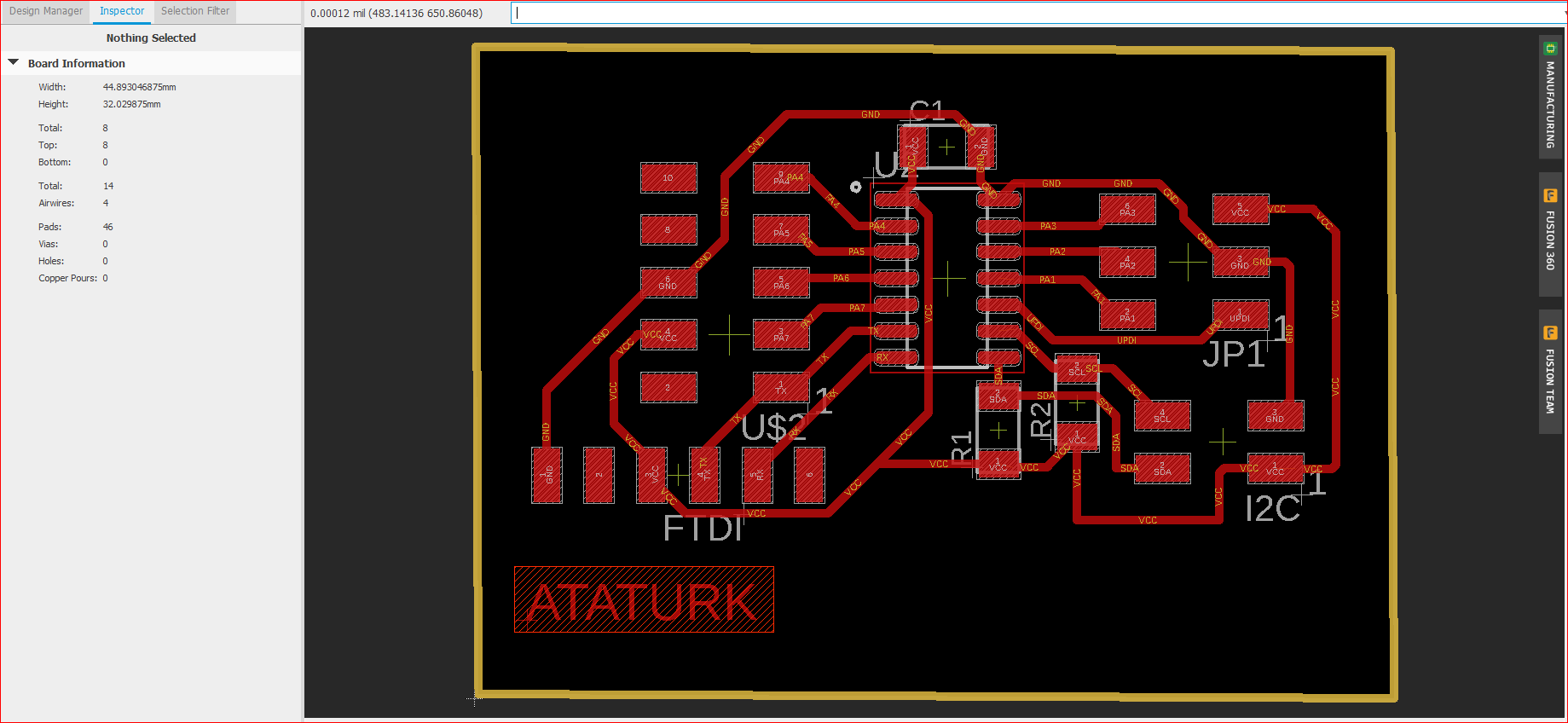
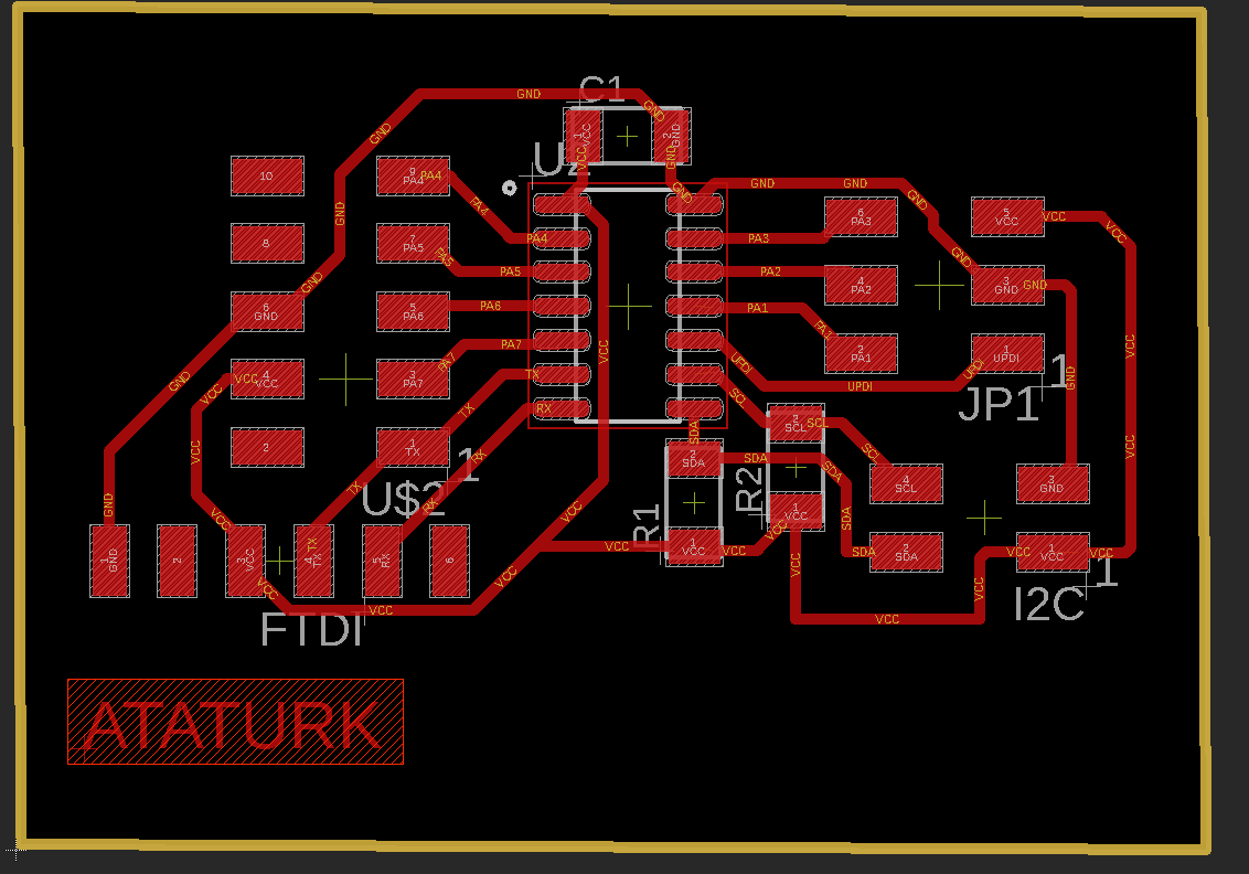
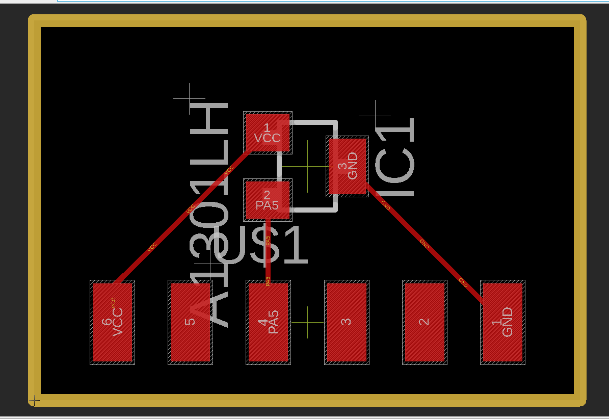
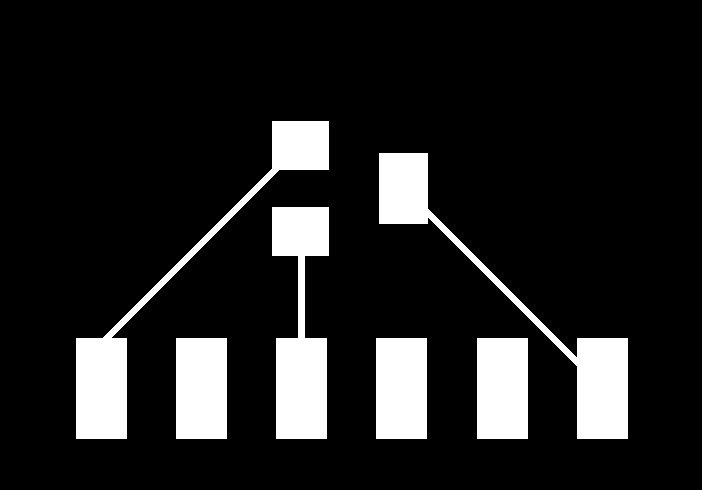
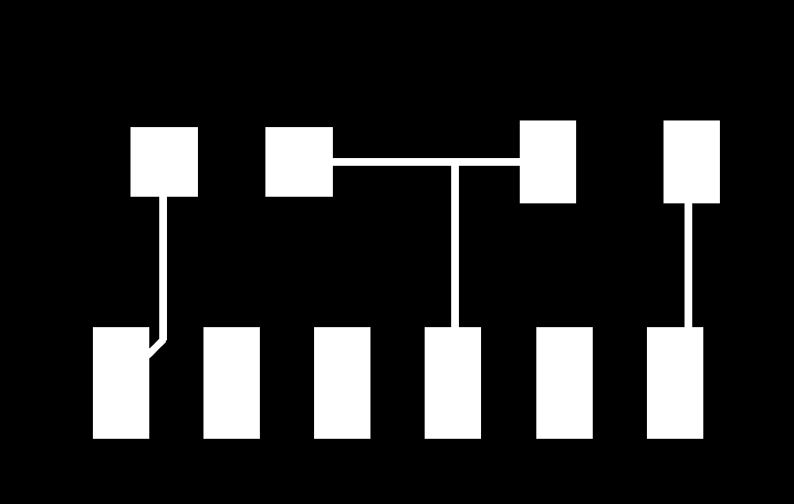
Board:
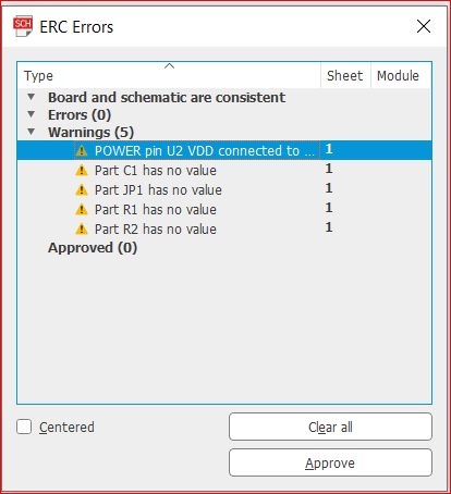
Trivial ERC Errors:
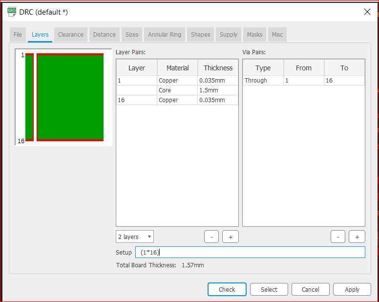
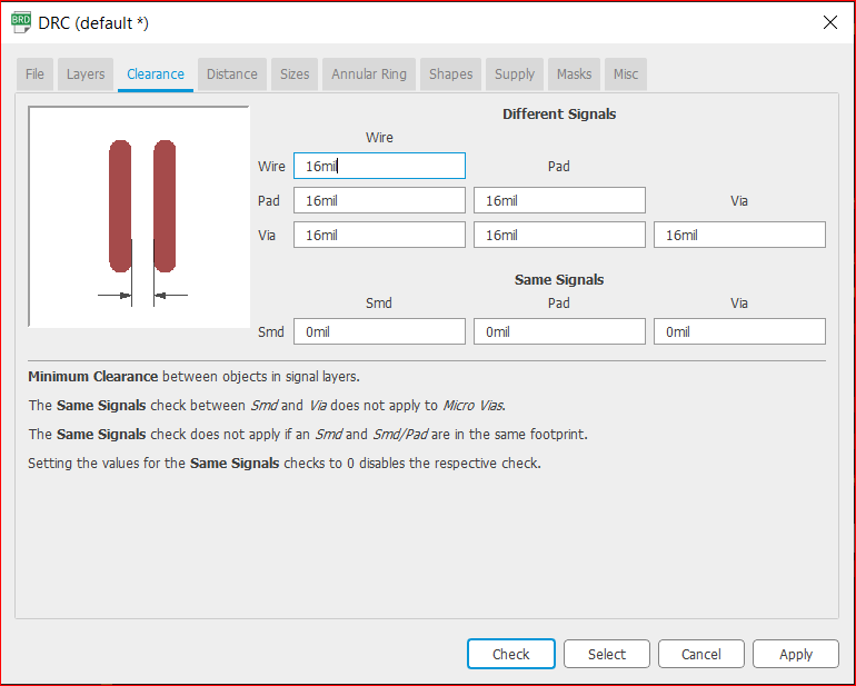
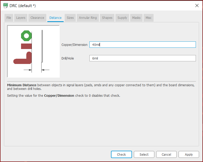
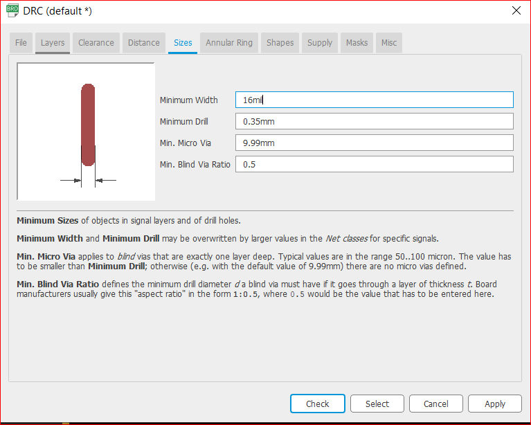
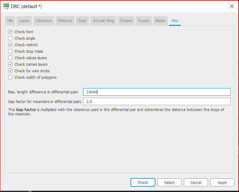
DRC:
Image for Reference:
Traces:
Outline:
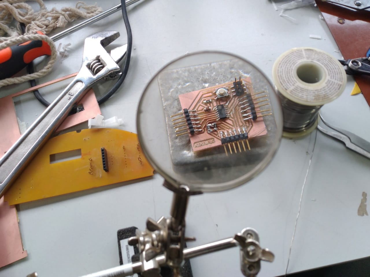
Fabrication:
Programming:
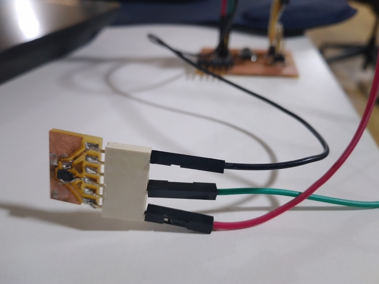
I programmed my microntroller using UPDI pin, with the help of megaTinyCore library, and I used UPDI + VCC module.
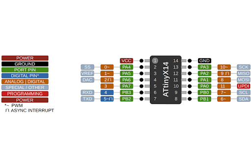
Pinout for Programming:
Input Devices/Sensors, I tried[Thanks to Adrian Torres, for a lot of inspiration: here]:
Button
Ultrasonic Sensor
Hall-Effect Sensor
Phototransistor
Thermistor
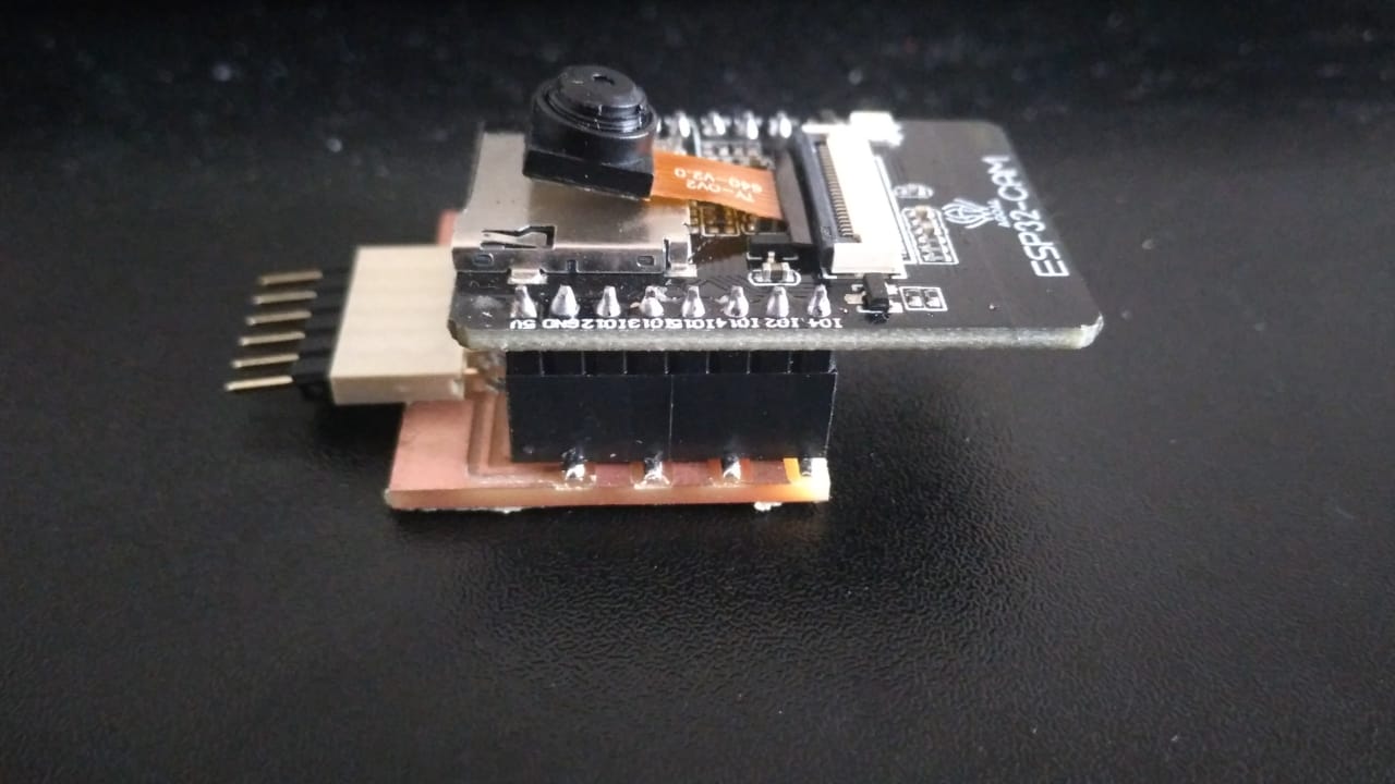
Camera
Button:
int inPin = 10;
int outPin = 0;

int state = HIGH;
int reading;
int previous = LOW;

long time = 0;
long debounce = 200;

void setup()
{
  pinMode(inPin, INPUT);
  pinMode(outPin, OUTPUT);
}

void loop()
{
  reading = digitalRead(inPin);


  if (reading == HIGH && previous == LOW && millis() - time > debounce) {
    if (state == HIGH)
      state = LOW;
    else
      state = HIGH;

    time = millis();
  }

  digitalWrite(outPin, state);

  previous = reading;
}
Ultrasonic Sensor:
                #include

                  int trigPin = 3; //Trig Pin for Ultrasonic Sensor
                  int echoPin = 2; //Echo Pin for Ultrasonic Sensor
                  int ledPin = 0;

                  long duration;
                  int cm;

                  char cstr[16];

                  void setup() {
                    Wire.begin(8);
                    Wire.onRequest(requestEvent);
                    pinMode(ledPin, OUTPUT);
                    digitalWrite(ledPin, HIGH);
                    pinMode(trigPin, OUTPUT); //Set Ultrasonic Trigger Pin as OUTPUT
                    pinMode(echoPin, INPUT); //Set Ultrasonic Echo Pin as INPUT
                    Serial.begin(9600);
                  }

                  void loop() {


                    digitalWrite(trigPin, LOW); //Write it to LOW
                    delayMicroseconds(2); // Wait for 2mus
                    digitalWrite(trigPin, HIGH); // Write the Trig Pin to HIGH
                    delayMicroseconds(10); // Wait for 10mus
                    digitalWrite(trigPin, LOW);// Write the Trig Pin to LOW

                    duration = pulseIn(echoPin, HIGH); //The duration the echoPin takes to go HIGH in microseconds

                    cm = microsecondsToCentimeters(duration);
                    sprintf(cstr, "%03d", cm);

                    Serial.println(cm);
                    delay(500);

                  }

                  long microsecondsToCentimeters(long microseconds){
                    return (microseconds / 29.15 ) / 2;
                  }

                  void requestEvent() {
                    Wire.write(cstr);
                  }
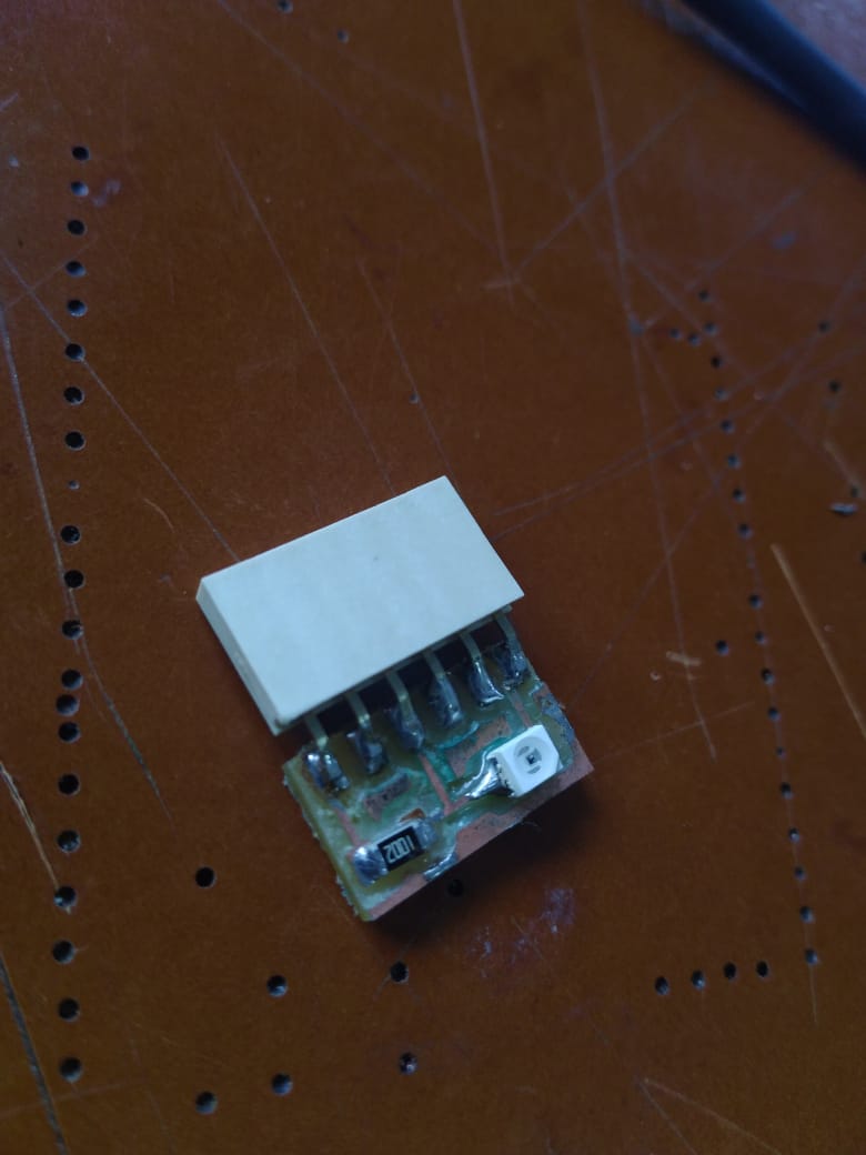
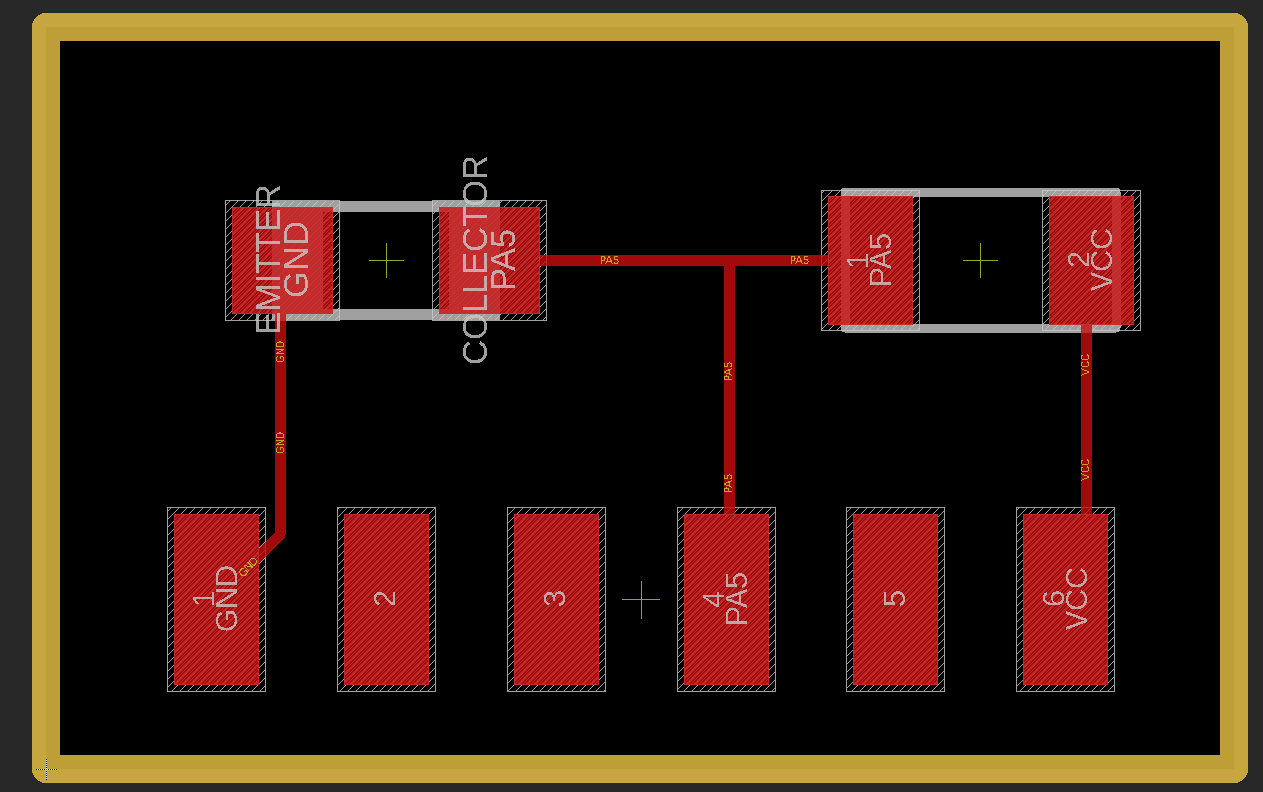
Hall-Effect Sensor:
Board:
Trace:
Outline:
Code:
int pin = 0;
int value = 0;

void setup() {
  Serial.begin(9600);
}

void loop() {
  value = analogRead(pin);
  Serial.println(value);
  delay(500);
}
As a group assignment, we probed hall sensor where the character of the hall sensor was visualized in the digital oscilloscope.
First the 5V is given from the Programmable DC Power Supply to the hall sensor and then, first set the oscilloscope to DC supply. Then autoset the oscilloscope. After there is a green liight in the Run/Stop, place the black wire to the ground and the vcc to the vout of the hall sensor.
Now after the circuit is completed, get a magnet and put it close to the hall sensor. You will notice that when you move your magnet closer to the sensor, there is a oscillation and when it is released suddenly, there is a immediate oscillation in opposite direction.
Similarly, when you bring one surface of a magnet closer it oscillates and if the magnet is flipped, the signal is also in the opposite direction.


