Purpose of the capacitor: Filtering the voltage fluctuations in the circuit.
Purpose of the Resistor: To guard against high voltage.
Some helpful hueristics: Think of Voltage as the velocity of the ball thrown upwards, Current as the mass of the ball, and air resistance/gravity as the resistance.
We were advised by our instructors to choose Autodesk Eagle, over KiCad, even though I preffered the latter. Thus, I downloaded Eagle.
6. Setting up Eagle, and designing the basic schematic:
Downloading Autodesk Eagle is straight-forward, you can go here for further instructions: Here
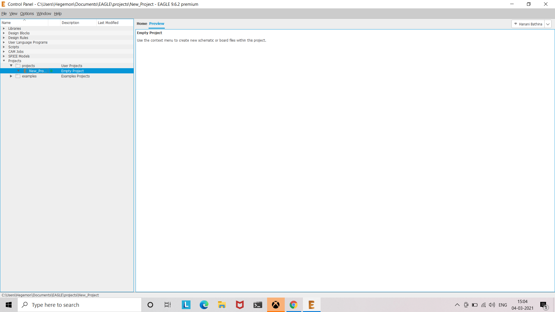
Standard eagle interface.
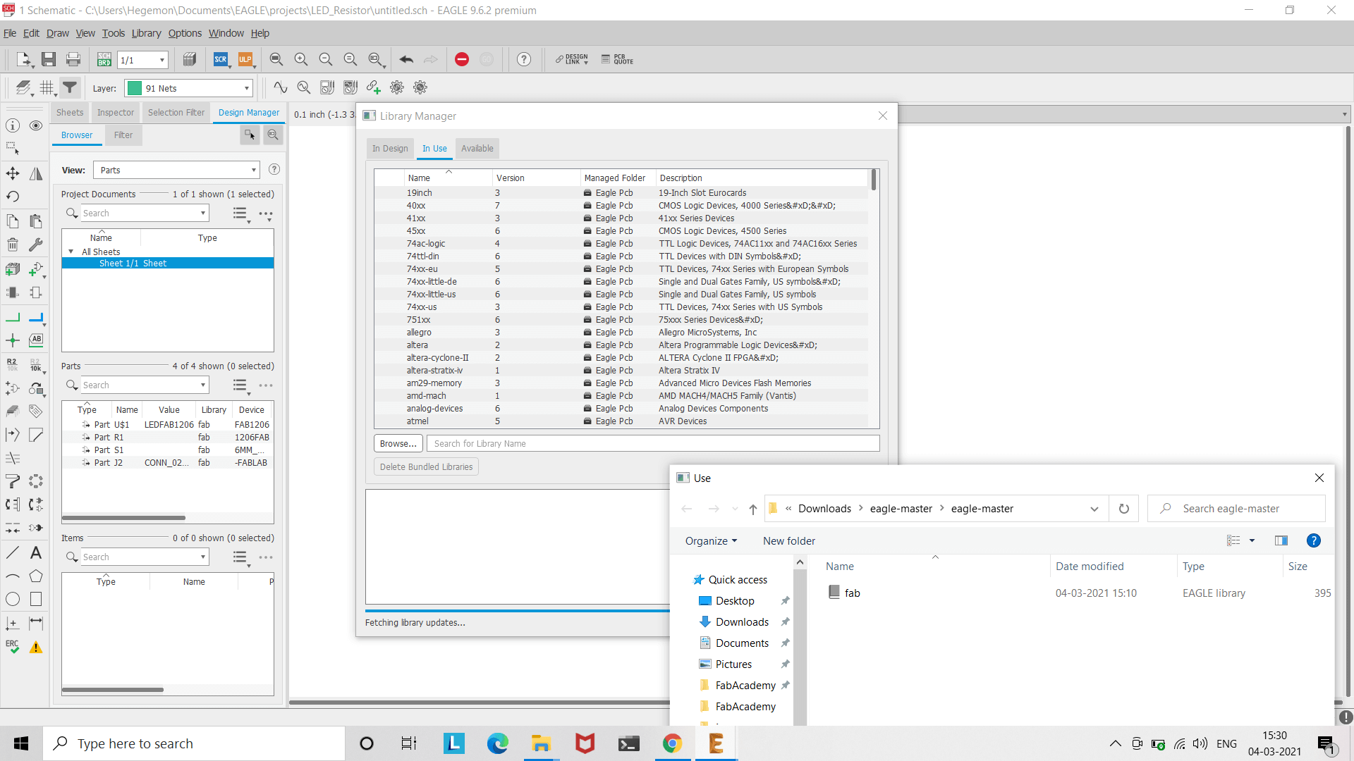
Download the components that are in standard-FabLab inventory for Autodesk Eagle from here.
Load the library up in Eagle.
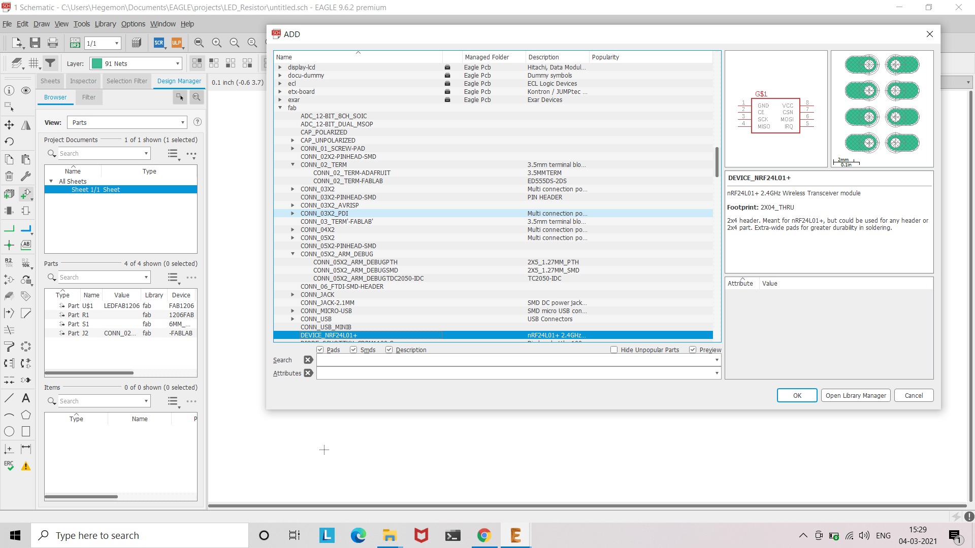
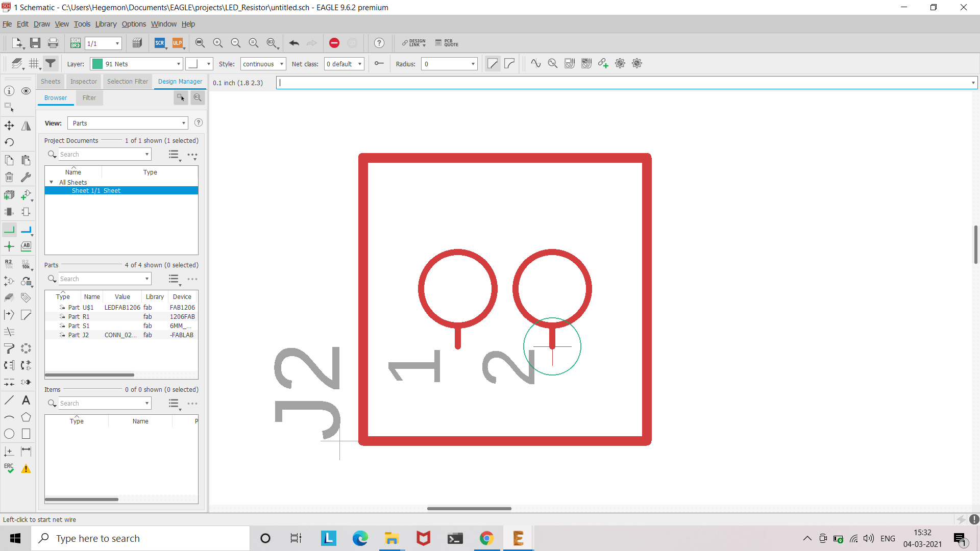
Start choosing components.
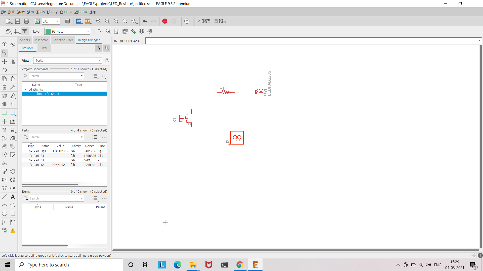
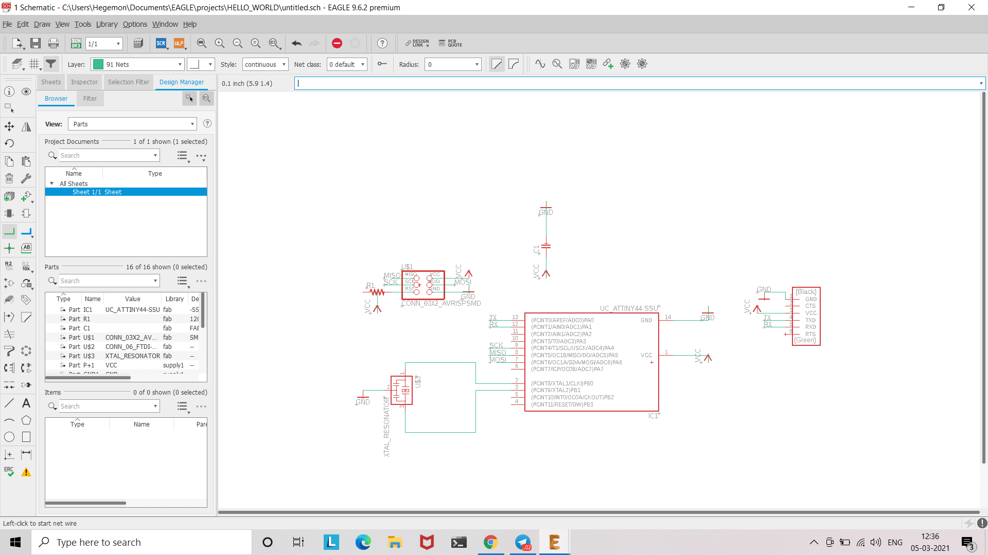
Load up all the necessary components on the schematic, and connect them using 'net' command, accordingly.
'Net' command.
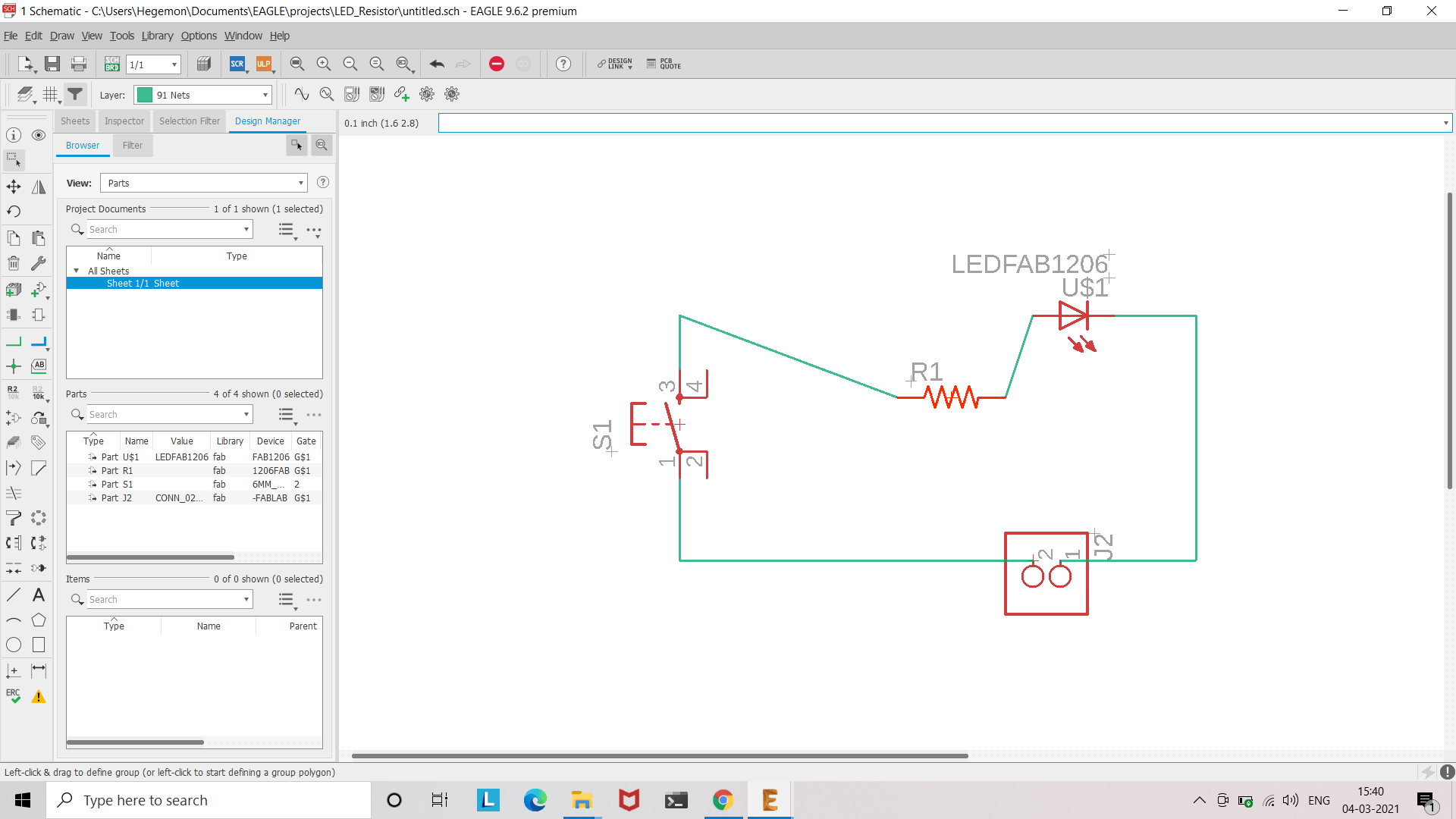
Arranging the components in a schematic.
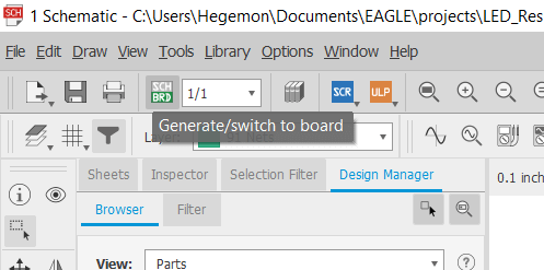
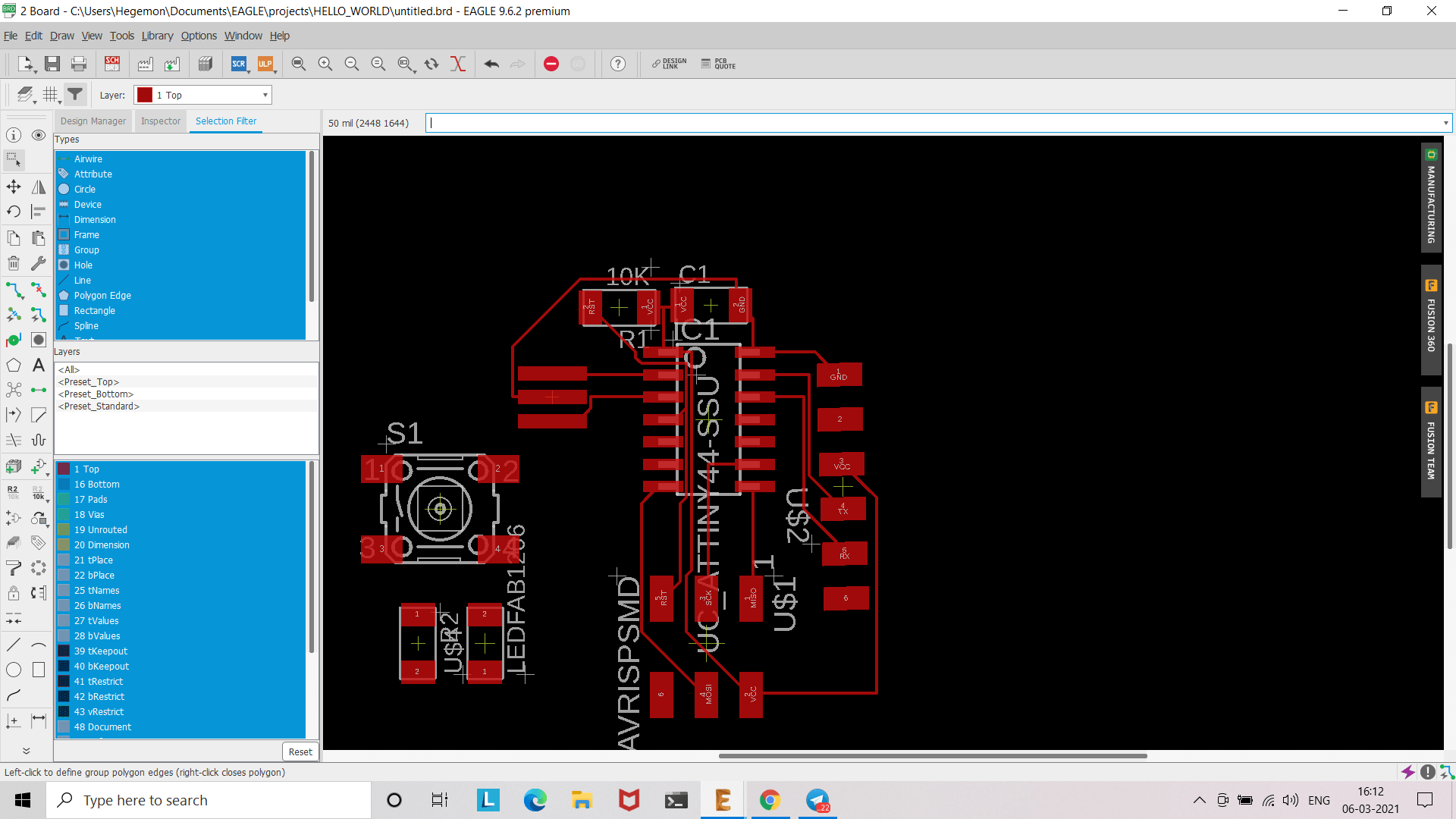
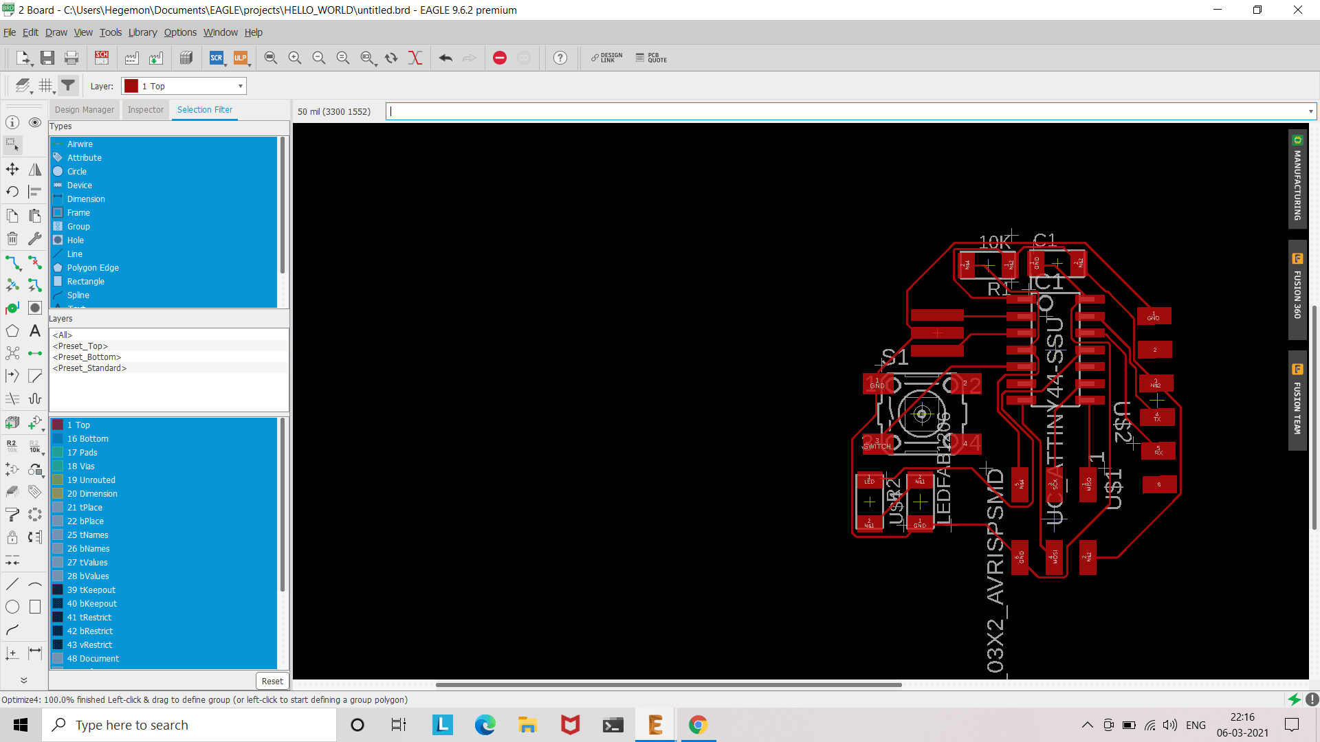
Switch to Board.
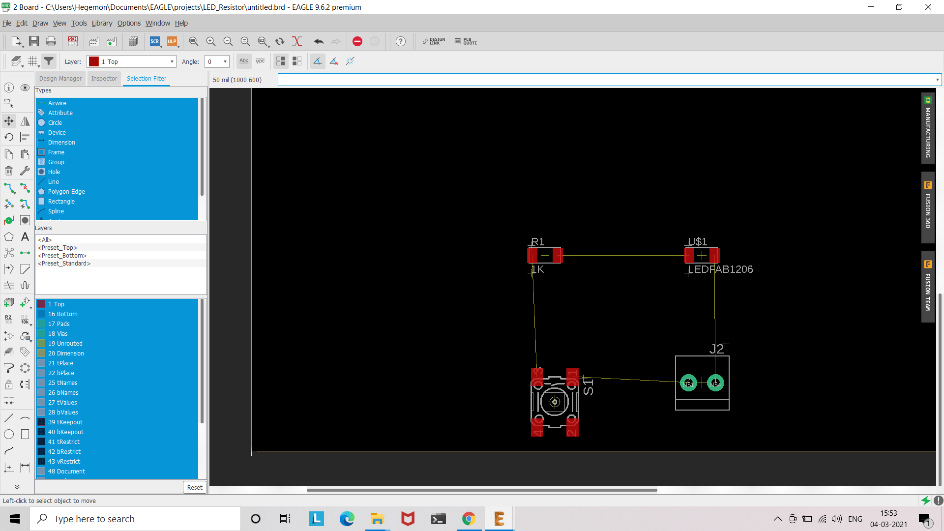
The interface of Board:
The next task is tracing. It can be done, either manually or by autorouter.
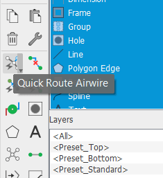
Quick_Route_Airwire tool in Eagle
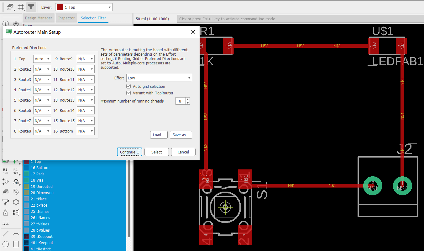
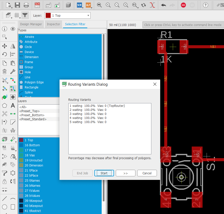
Autorouting workflow.
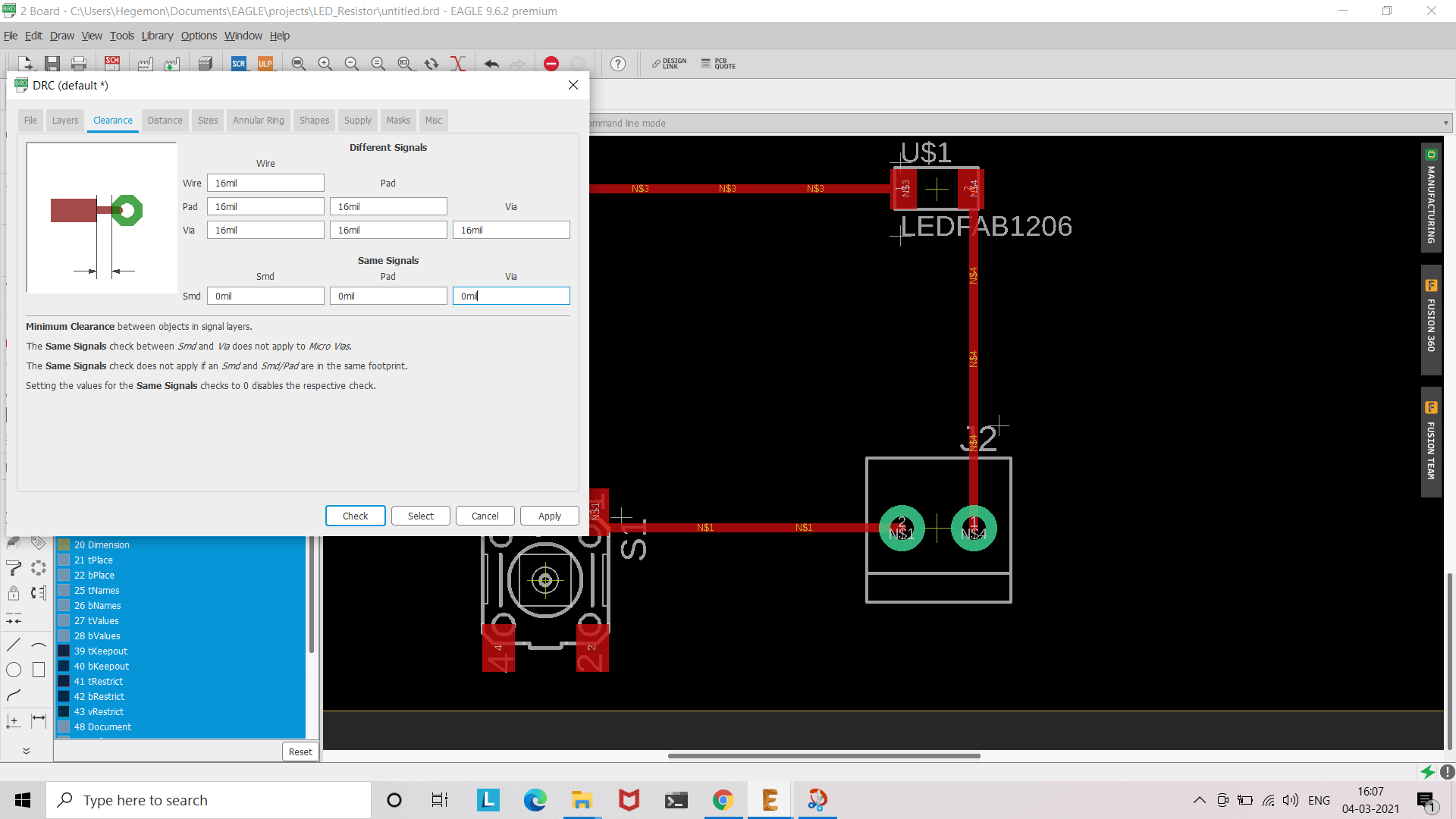
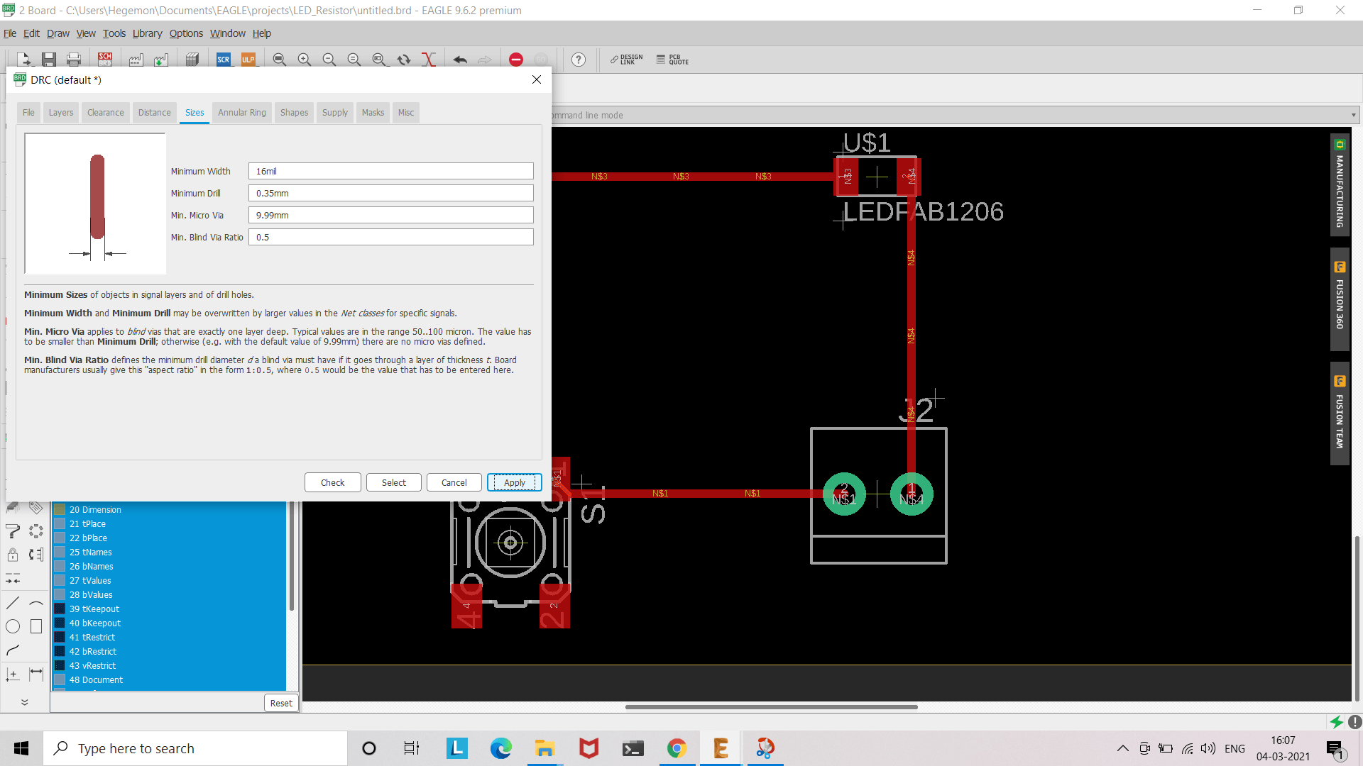
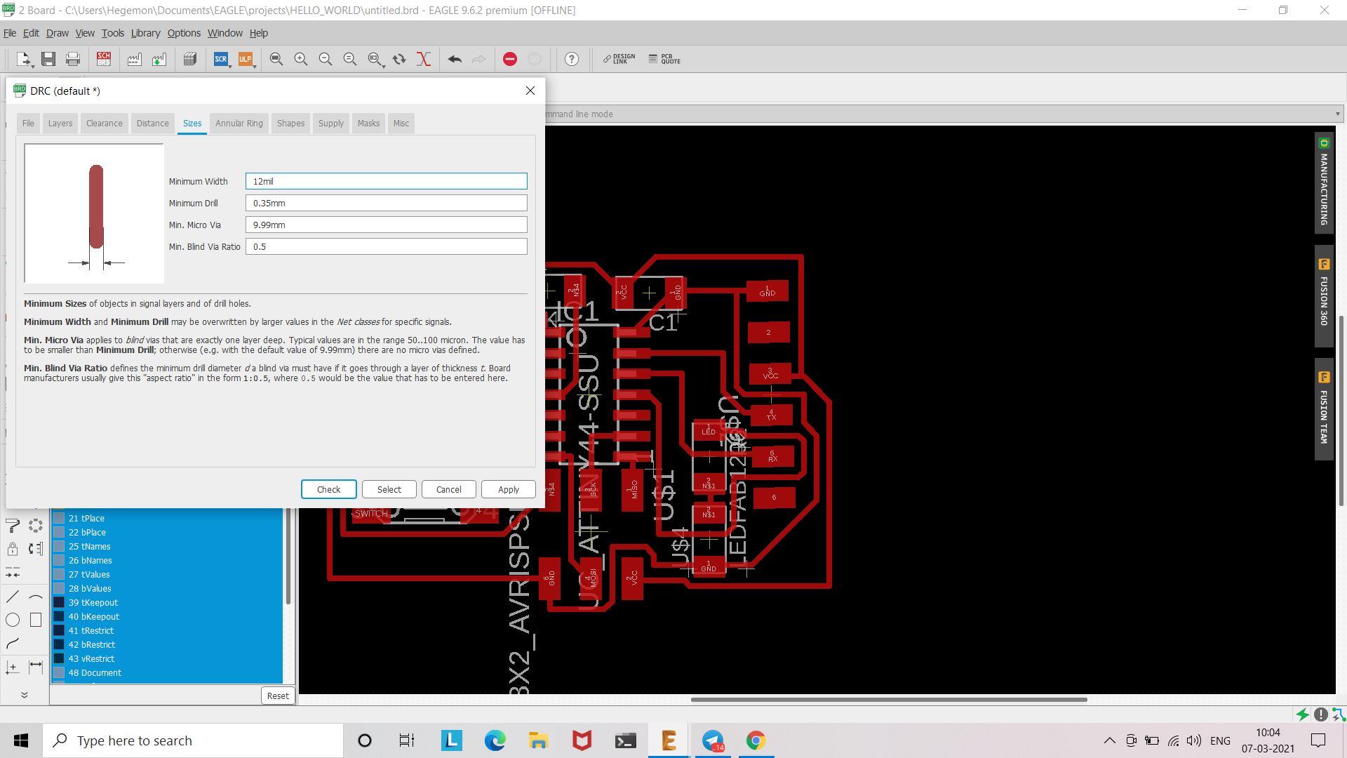
One more additional parameter to consider is DRC. Keeping in mind our milling machine, I set Clearance:16 mils, and Size:16 mills.
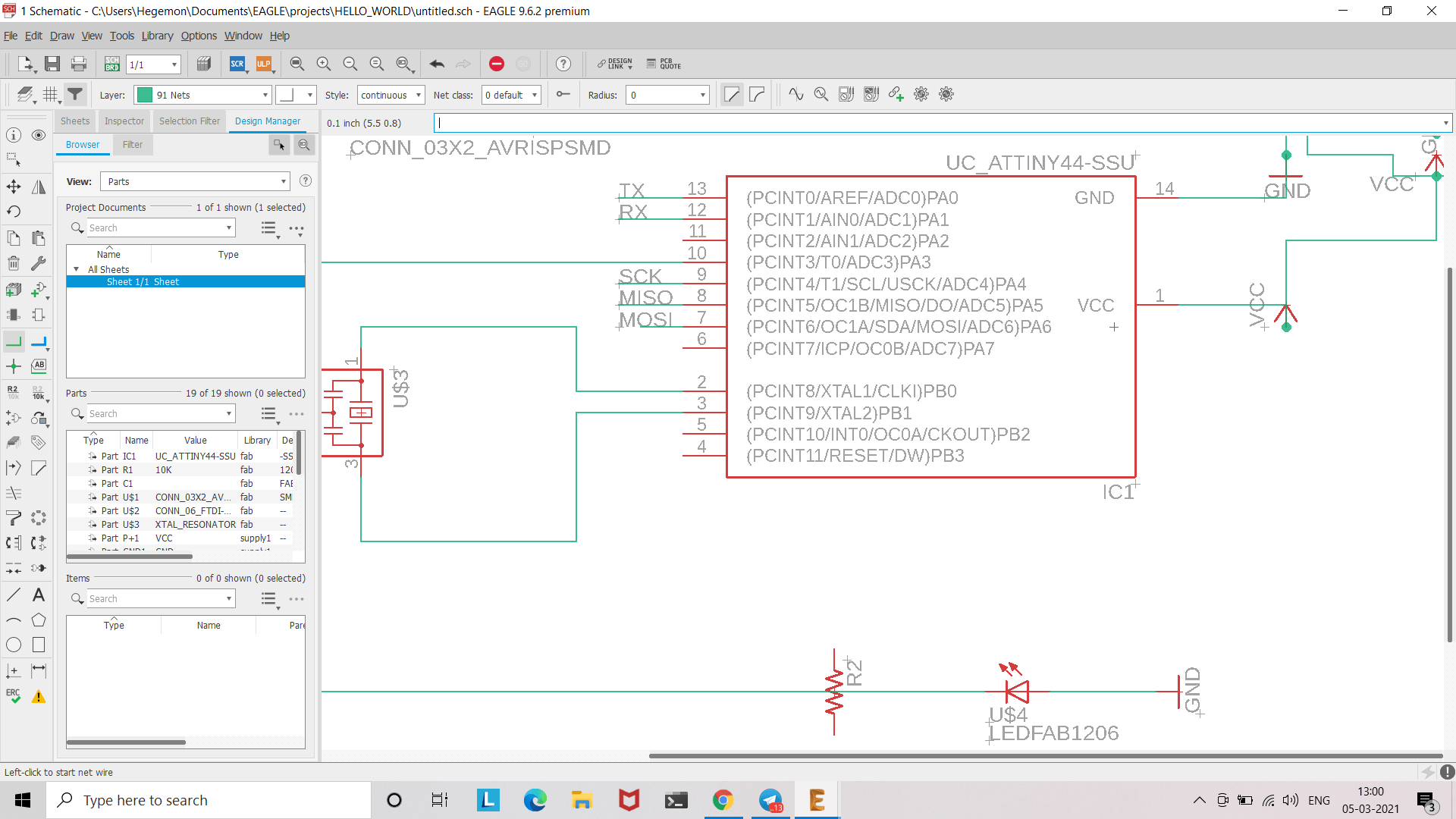
Then, I added a LED, and a 0.5K resistor to the schematic, yet again from the aforementioned library.
I had to do 'net/delete/re-net' plenty times, before I could come up with a stable one.
Then, I readily switched to the board interface, without realizing their lies the hardest part.
I spent a whole day trying to route the components, both manually and autoroute.
There was atleast one net that I could not route, and I had to re-align the components in a better place, and try doing it again.
Upon my mentor's advice, I deleted the extra connections to newly added components, and tried auto-routing. It worked.
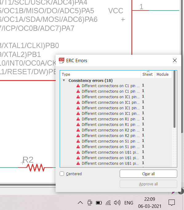
But, I encountered this:
ERC errors. Lost consistency.
Then, I had to go through an entire workflow of resolving this, which included exporting the 'Netscript' from the schematic, ripping up the existing board traces, and loading the 'netscript' file directly in the board interface, through SCR.
Consult this, if you encounter the same problem.
I auto-routed my board, afresh. It looked like it worked. Once I closed the auto-route window, there was still one net that wasn't routed. Some compromise had to be made.
I chose to reduce the minimum_width to 12 from 16.
It got routed. The board is connected.
Done.
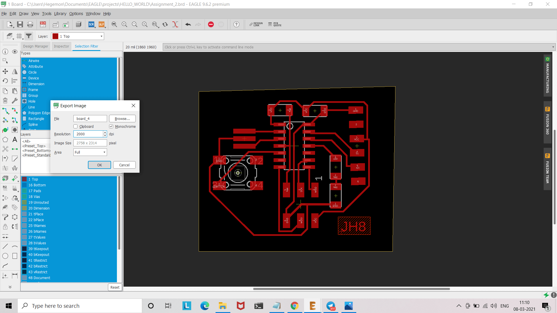
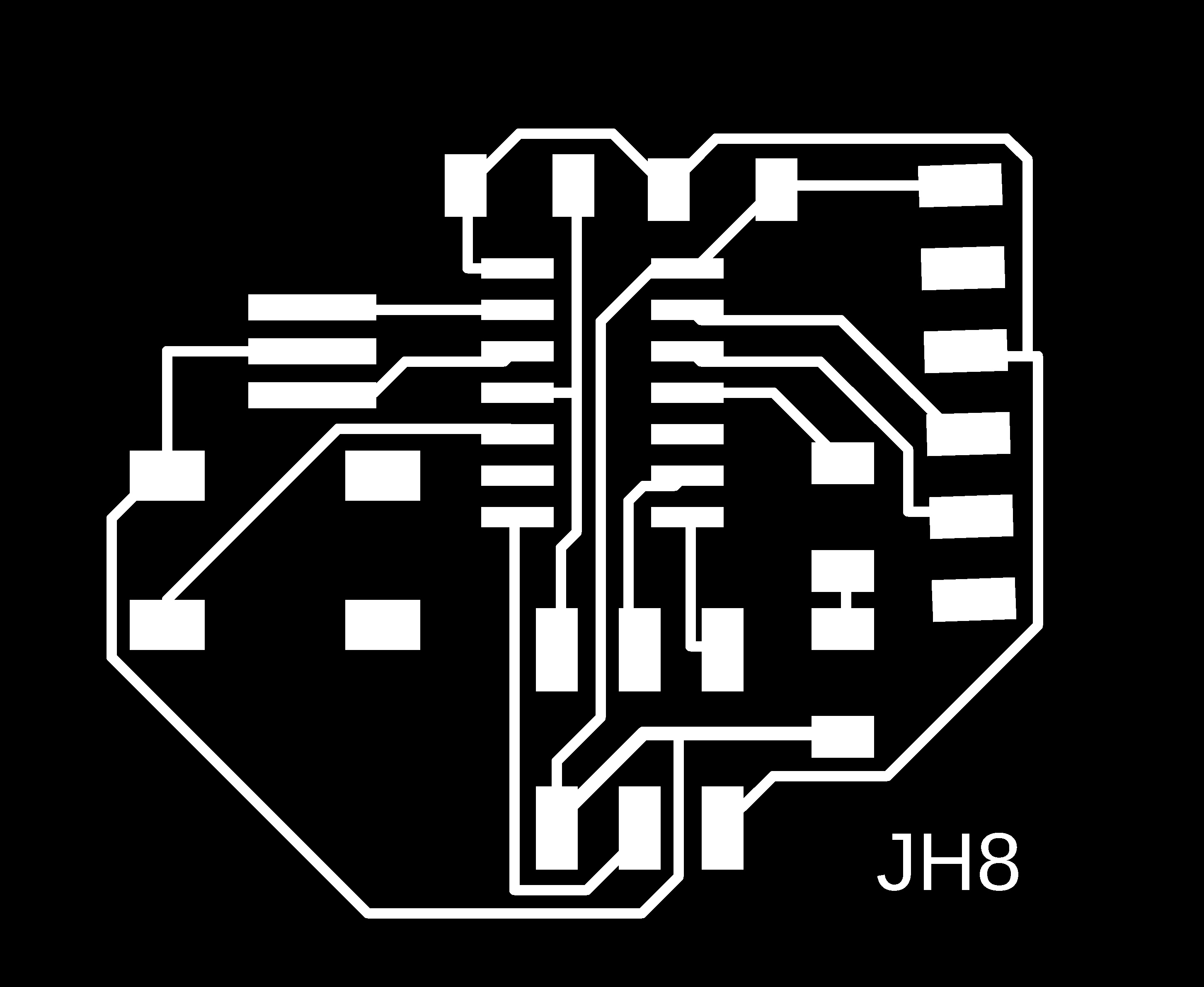
I exported the board as a monochrome image with 2000 dpi.
I made a cut file too, and exported it, also, as a monochrome image with 2000 dpi.
Here are the final results:
The Mill File
The Cut File
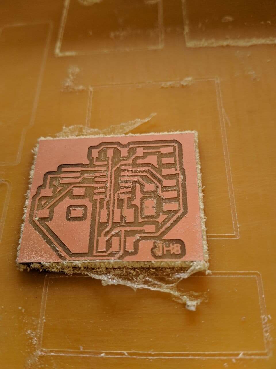
9. Milling & Programming:
I replicated the milling process of Electronics Production week, as detailed here
Here is the result:
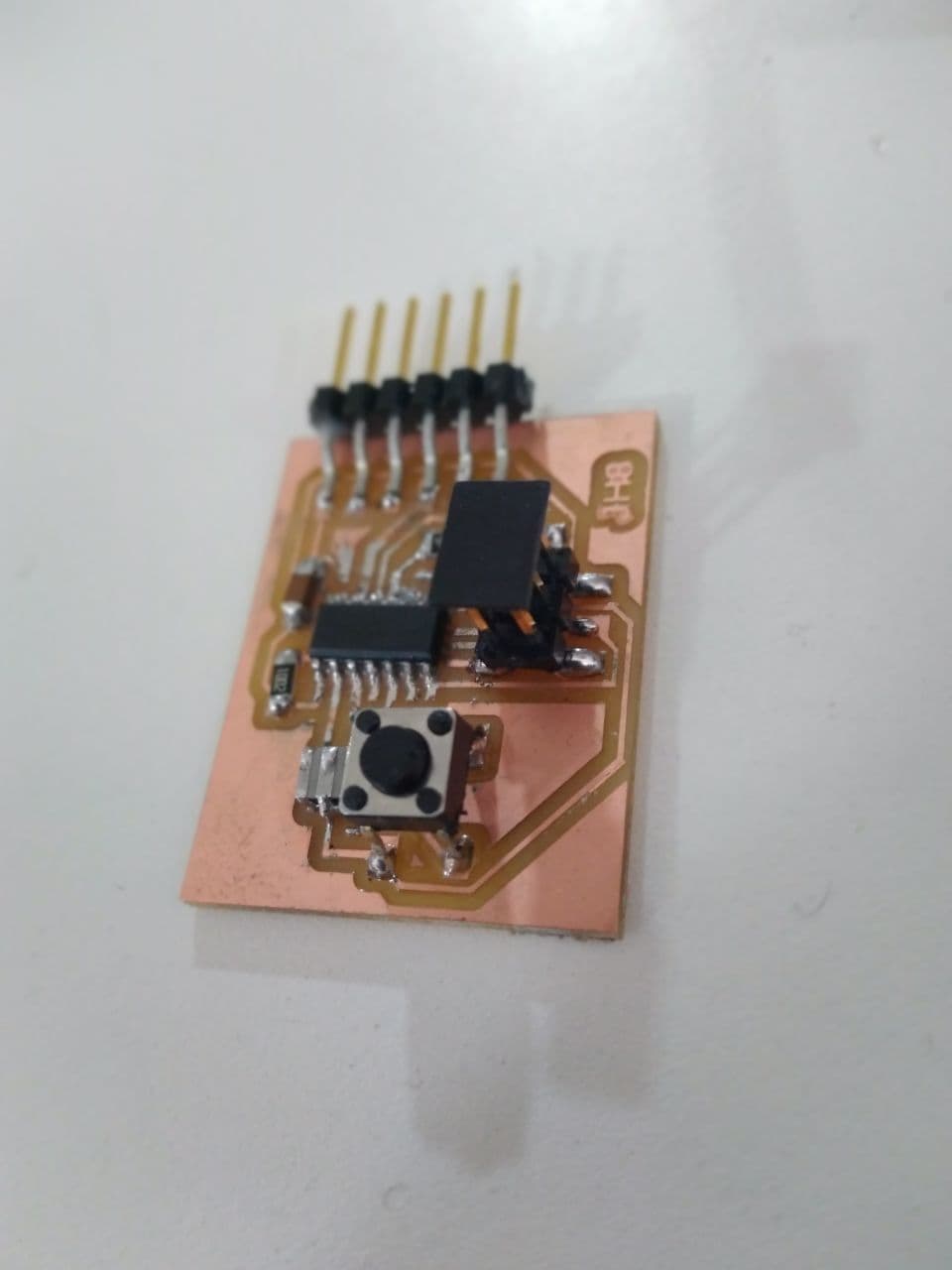
Soldered it up:
Next, Go to File >> Preferences in Arduino IDE
Paste this link in "https://raw.githubusercontent.com/damellis/attiny/ide-1.6.x-boards-manager/package_damellis_attiny_index.json" Additional Board Manager URLs
In the Board Manager, Search for ATTiny44 and install it.
In Menu >> Tools, Select Board >> ATTiny24/44/84, Processor >> ATTiny84, Clock >> External 20MHz
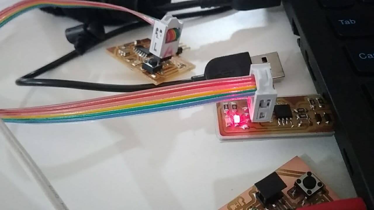
I flashed it using ISP, I made in Electronics Production week.
There was some problem with the LED. The polarity was wrong. I corrected it.
The bulb was on, indefinitely.
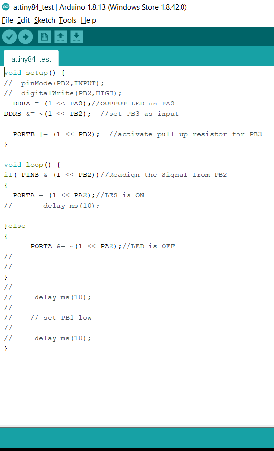
It was, then, programmed to not light-up when the switch was pressed.
void setup() {
    DDRA = (1 << PA2);//OUTPUT LED on PA2
  }

  void loop() {
    PORTA = (1 << PA2);//LED is ON
    delay(500);
    PORTA &= ~(1 << PA2);//LED is OFF
    delay(500);
  }
This week's assignment was to use the test equipment in your lab to observe the operation of the various electrical characteristics of a microcontroller.
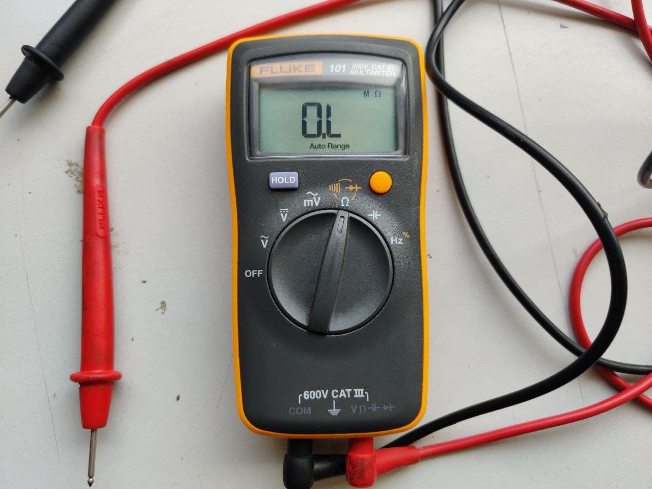
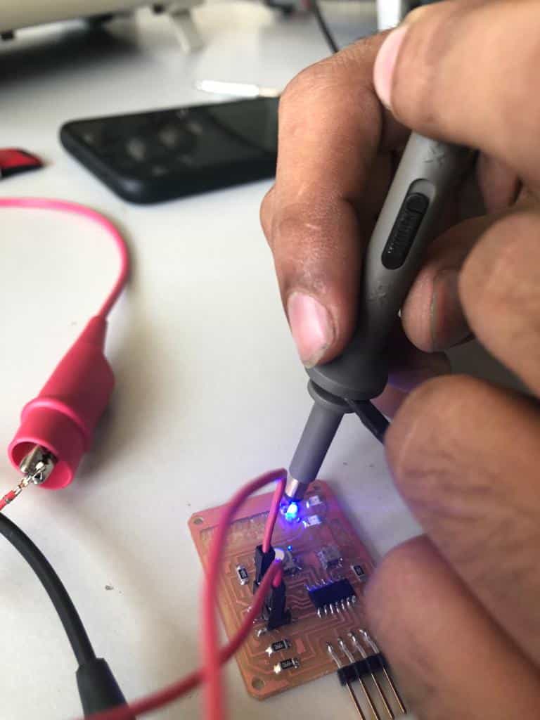
FLUKE 101 Pocket Digital Multimeter
A multimeter is a tool for testing different parameters of an electronic circuit board. Here are the tests which can be conduced using a multimeter:
Voltage
Current
Continuity
Resistance
Frequency
Capacitance
FLUKE 101 Pocket Digital Multimeter
Specifications:
V AC Range: 600.0 V
V DC Range: 600.0 V
Ohms Range: 40.00 MΩ
Capacitor: 100.0 μF
Frequency: 100.0 kHz
Size: 130 mm x 65 mm x 27mm
Using multimeter we had checked the voltage and got a voltage of 5.35V.
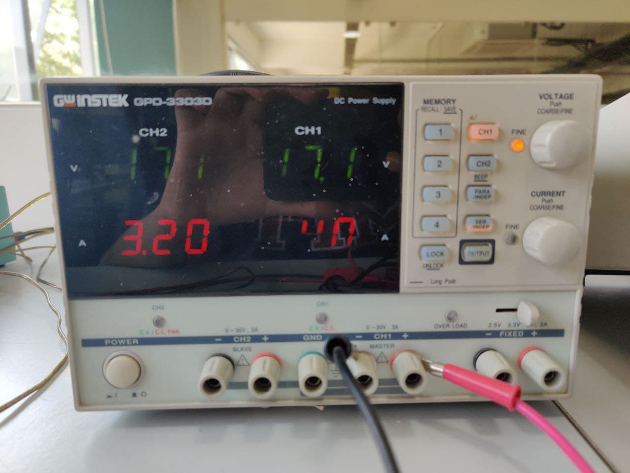
INSTEK GPD-3303D Power Supply
Instek GPD-3303D is a Multiple Output Programmable Linear D.C. Power Supply. The GPD-X303 Series offers digital panel control, large display, bright LED indicators, high output resolution, 4 sets of setup memory, USB remote control and smart cooling fan control. Additionally , the GPD-X303S Series provides easy operation , a wide selection of panel setting and operation.
Features:
2/3/4 Independent Isolated Output
4 LED Display Sets: 3 digits after decimal point
1mV/1mA(GPD-2303D/GPD-3303S/GPD-4303S)
100mV/10mA(GPD-3303D)
4 Sets Save/Recall
Output on/off
Tracking Series and Parallel mode
USB Standard Interface
Labview driver
INSTEK GPD-3303D Power Supply
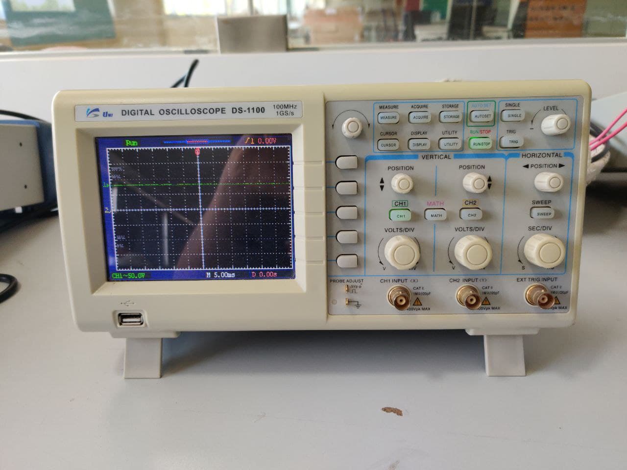
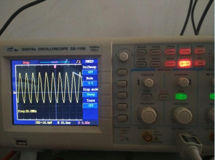
UNISOURCE DS-1100 100 MHZ, 2 CH, Digital Storage Oscilloscope
The digital storage oscilloscope is an instrument which gives the storage of a digital waveform or the digital copy of the waveform. It allows us to store the signal or the waveform in the digital format, and in the digital memory also it allows us to do the digital signal processing techniques over that signal. The maximum frequency measured on the digital signal oscilloscope depends upon two things they are: sampling rate of the scope and the nature of the converter. The traces in DSO are bright, highly defined, and displayed within seconds.
UNISOURCE DS-1100 100 MHZ, 2 CH, Digital Storage Oscilloscope
Features:
100 MHz bandwidth, 1 M Memory
USB storage, RS232C & J45 interface
4000 point record length for each channel
Multi-waveforms math, FFT Function
Cursor & Track measurement
Waveform Record & Recall, Trigger Mode for Edge, Video, Pulse Width, Slope & Alternate
Here we used oscilloscope for checking the frequency generated by the Resonator and got 20MHz as the frequency.
Oscilloscope Readings
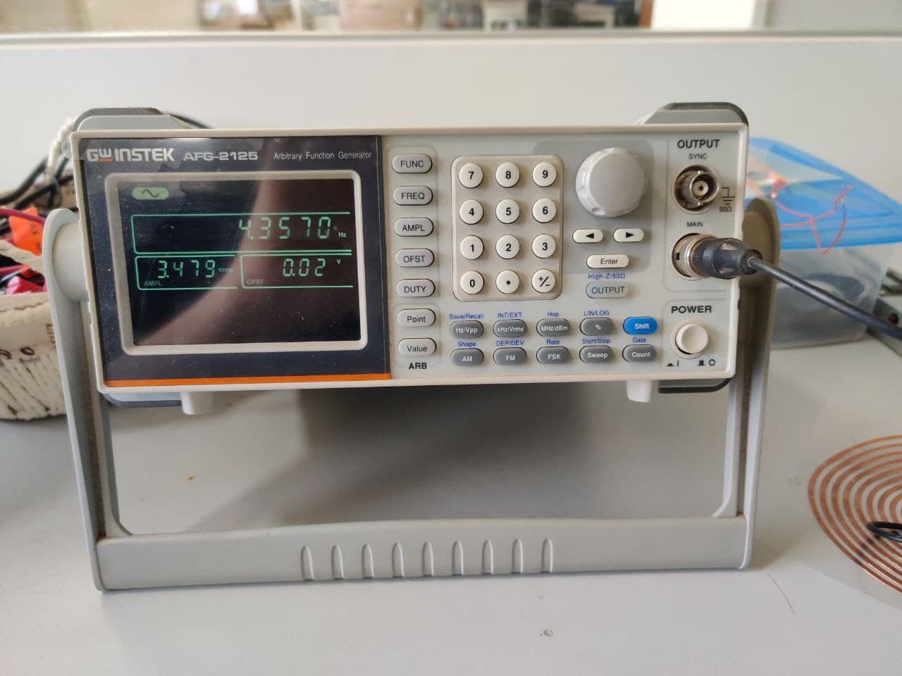
AFG-2100/2000 SERIES ARBITRARY FUNCTION GENERATOR
A function generator is a specific form of signal generator that is able to generate waveforms with common shapes. Unlike RF generators and some others that only create sine waves, the function generator is able to create repetitive waveforms with a number of common shapes.
The AFG-2100/2000 Series Arbitrary Function Generator is a DDS (Direct Digital Synthesized) based signal generator designed to accommodate the Educational and Basic Industrial requirements for an accurate and affordable signal source covering the output of Sine, Square (Pulse),
Ramp (Triangle), Noise and Arbitrary waveforms.
AFG-2100/2000 SERIES ARBITRARY FUNCTION GENERATOR
Features:
0.1Hz to 25MHz with in 0.1Hz Resolution
Sine, Square, Triangular, Noise and Arbitrary Waveform
1% ~ 99% adjustable duty cycle for Square Waveform
Waveform Parameter Setting Through Numeric Keypad Entry & Knob Selection
Amplitude, DC Offset and Other Key Setting Information Shown on the 3.5" LCD Screen Simultaneously
AM/FM/FSK Modulation, Sweep, and Frequency Counter Functions (AFG-2100 only)
PC Arbitrary Waveform Editing Software
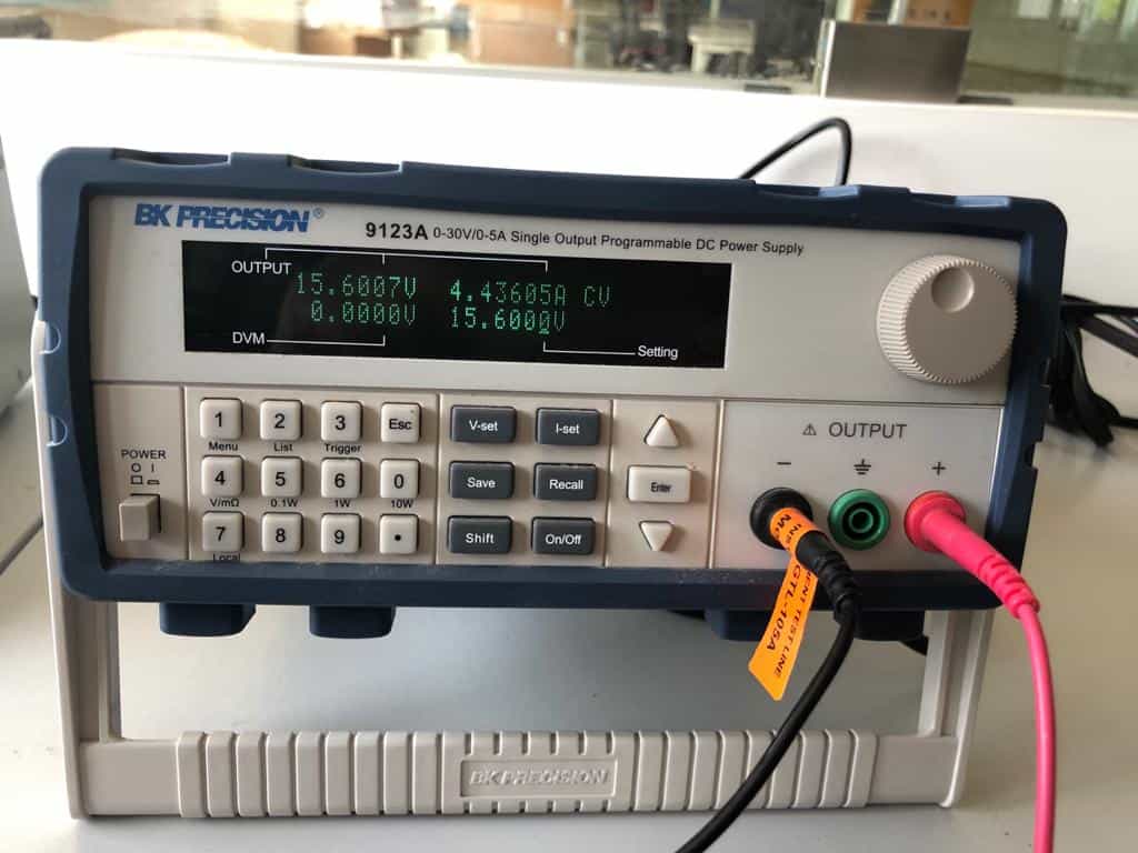
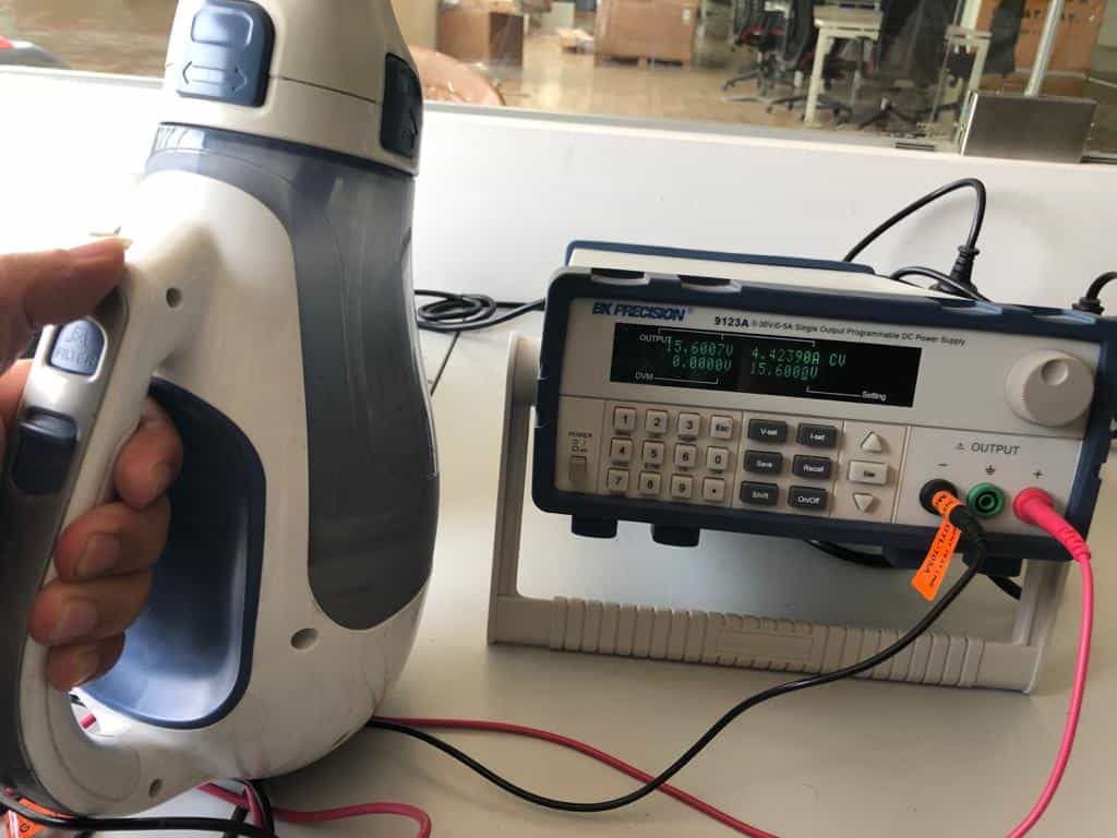
BK PRECISION 9123a series Programmable DC Power Supply
The 9120A series are laboratory grade, programmable DC Power Supplies providing great performance and features not found in other supplies in this price category. The power supplies were designed to meet the needs of today's applications in R&D design verification, production testing or university labs that require clean and reliable power, high resolution/accuracy and fast transient response time.
BK PRECISION 9123a series Programmable DC Power Supply
Features:
SCPI compatible
Communicate via USB Interface, using included USB to TTL serial converter cable
Compact size for bench use or rack mountable (2U x 1/2U size)
Discrete Fault Indicator/Remote Inhibit (DFI/RI). Useful for turning multiple power supplies On/Off simultaneously
Application Software for front panel emulation and simple test sequence generation included
Sheathed banana plug terminals for safety
This test has been conducted to to calculate current, in the circuit.
The power of vacuum cleaner was calculated as 69W from the power supply by setting rated voltage of 15.6V

