2.Group Assignment: test runout, alignment, speeds, feeds, and toolpaths for your machine
3.Individual Assignment:
Files:
Tools:
A CNC machine is a motorized maneuverable tool and often a motorized maneuverable platform, which are both controlled by a computer, according to specific input instructions. Instructions are delivered to a CNC machine in the form of a sequential program of machine control instructions such as G-code and M-code, then executed. The program can be written by a person or, far more often, generated by graphical computer-aided design (CAD) software and/or computer aided manufacturing (CAM) software. In the case of 3D printers, the part to be printed is "sliced", before the instructions (or the program) is generated. 3D printers also use G-Code.
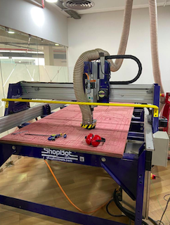
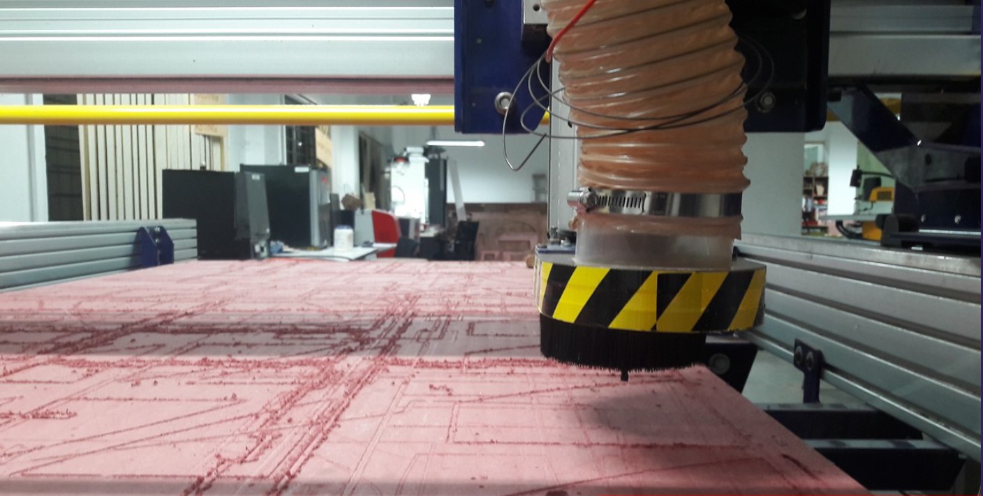
In our lab at Kochi, we have the Shopbot. Shopbot is a 3 axis machine the Z axis is perpendicular to the bed. The X and Y axis are the length and the breadth of the machine respectively.To have a rigid supporting layer on the bottom of the workpiece we will place an additional piece of plywood above the bed called sacrificing layer. The sacrificing layer also protects the millig bit from damage by avoiding unwanted intereference with the metal body. It can be used to cut timber, plywood, soft aluminum etc and has a bed size of 4x8 feet. The shopbot also has a dust collector that sucks in all the dusk while cutting.
Maybe owing to the fact that we couldn't access the lab for 2 days, or that I had an exam over the weekend, this was the hardest week for me, yet. At the same time, I learned the most in this week.
I, prelimarily, wanted to build a squat-rack for my gym.

After talking to my instructor, I realized the infeasability. The wood I will be given is just 12 mm. Such thin wood cannot handle that loads.
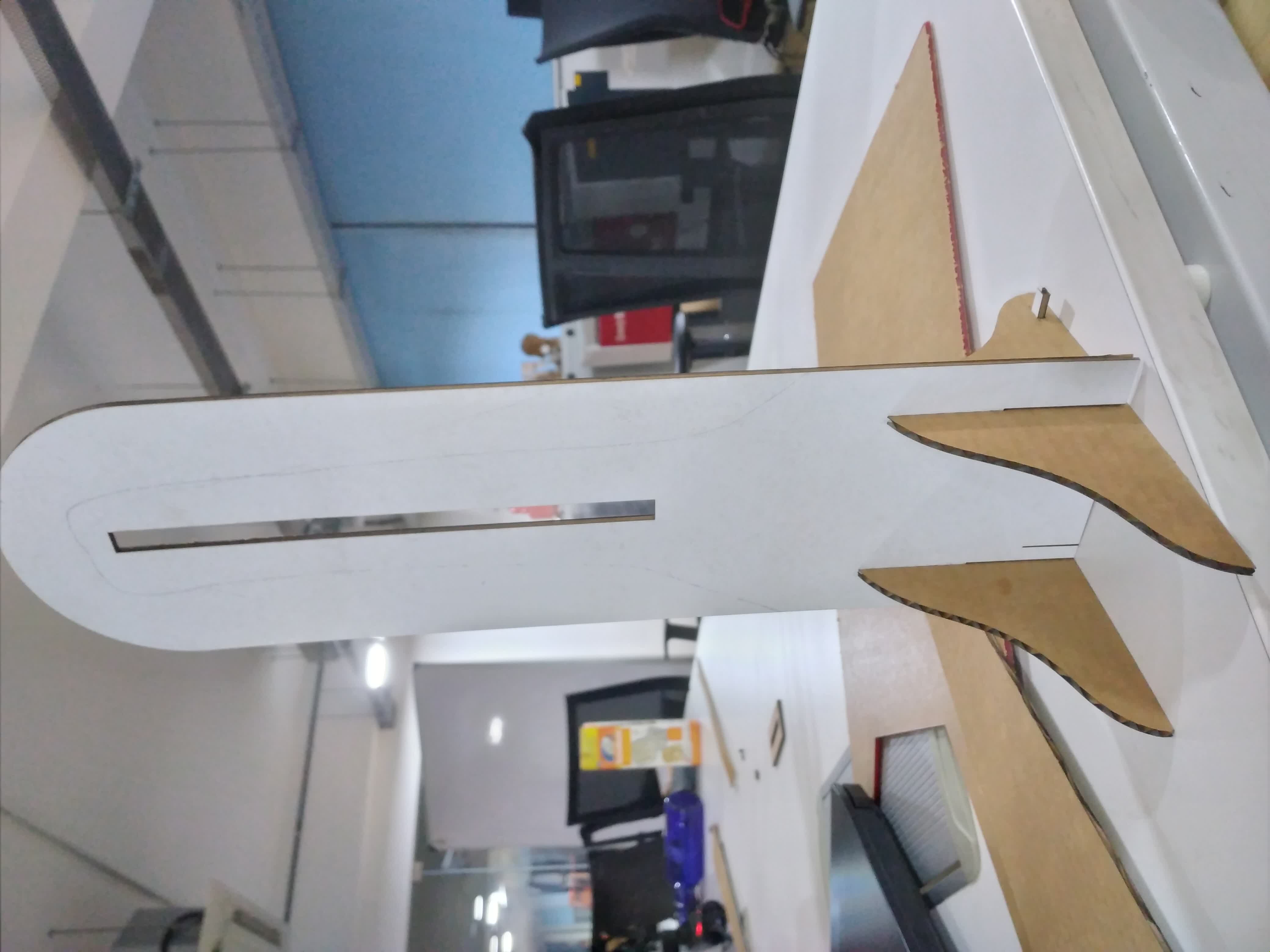
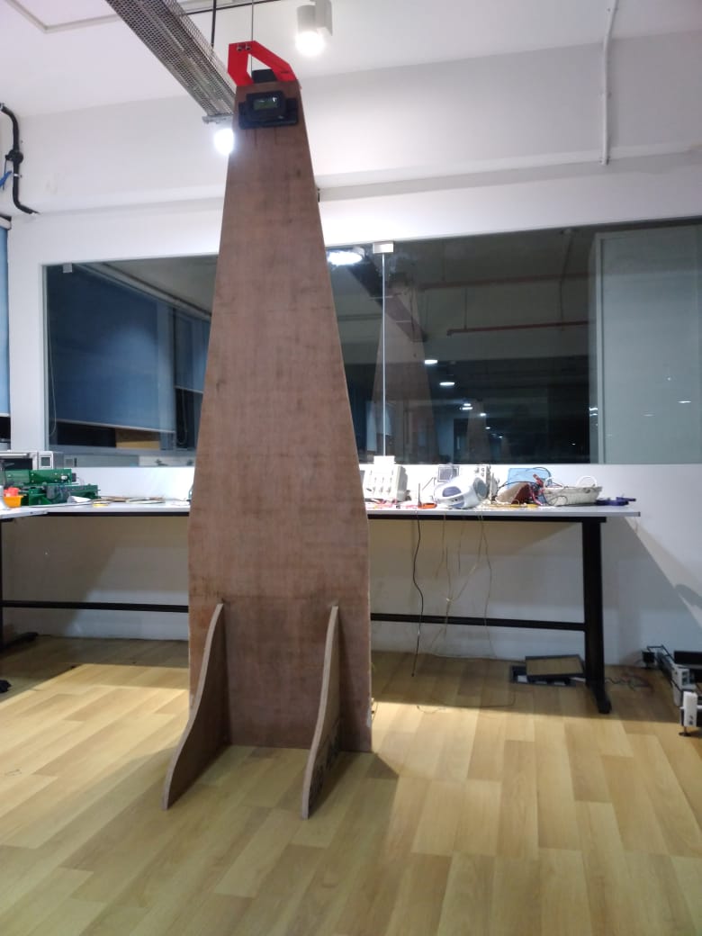
Then, I decided that I will build a height measuring board. Something like this:

There was a lot of trial-error in my design, this week.
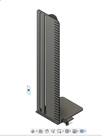
This particular one was a tad-bit structurally unstable. I had to change it.
This was the second-iteration.
I used acrylic to cut out the design in a Trotec laser-cutter. Here's the result.
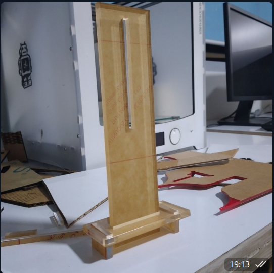
There was still some translational motion, thus wobbling. I altered the deisgn, and made it simple and to-the-point.
I was not convinced of the stability of the current design, I altered it further.

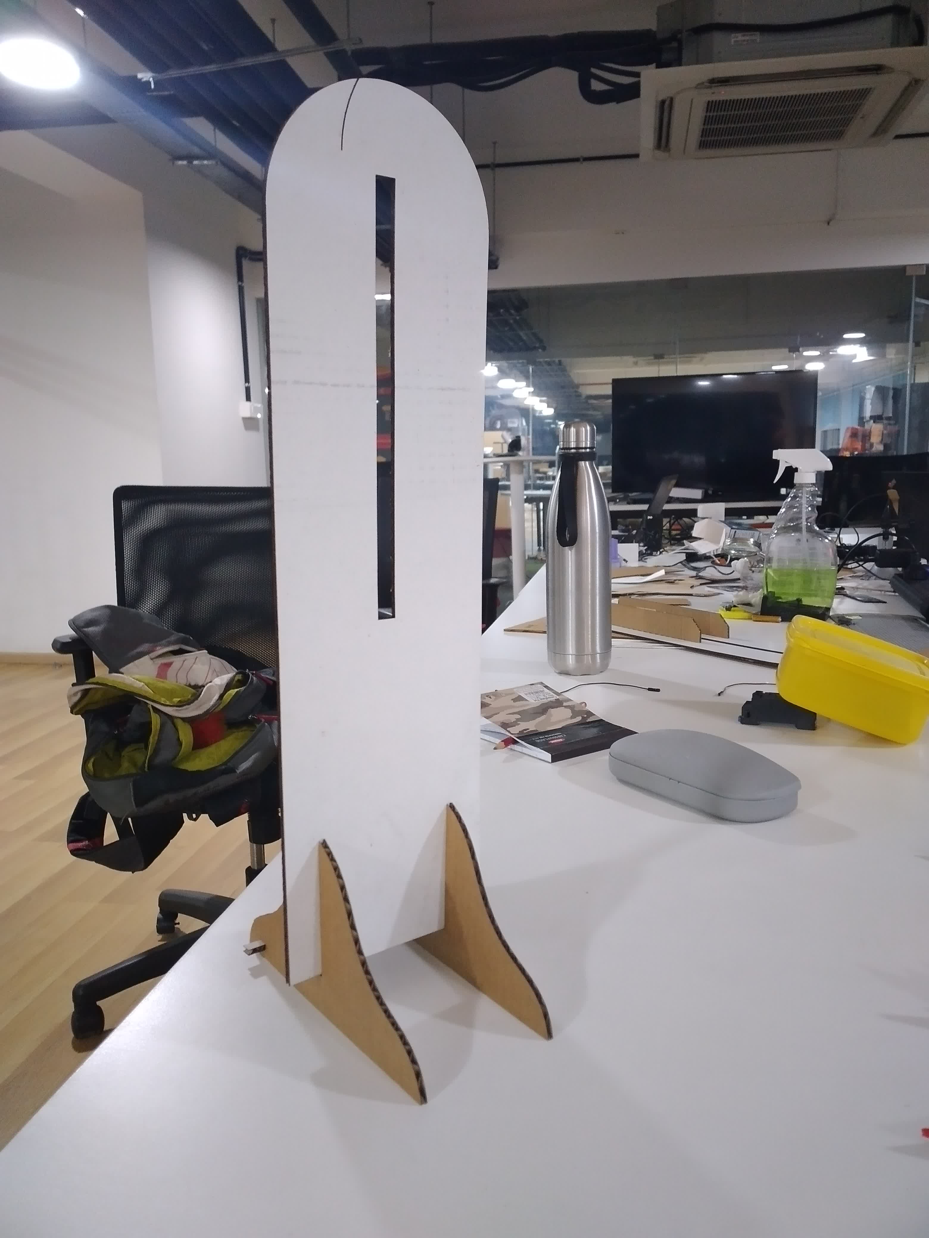
Cardboard-Cut:

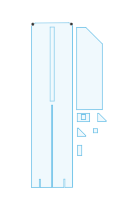
Still unsatisfied of the stability of the structure. I sat down started sketching it, with dimensions.

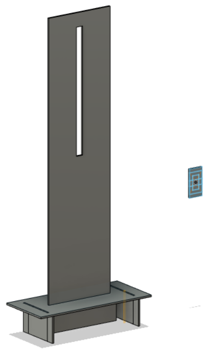
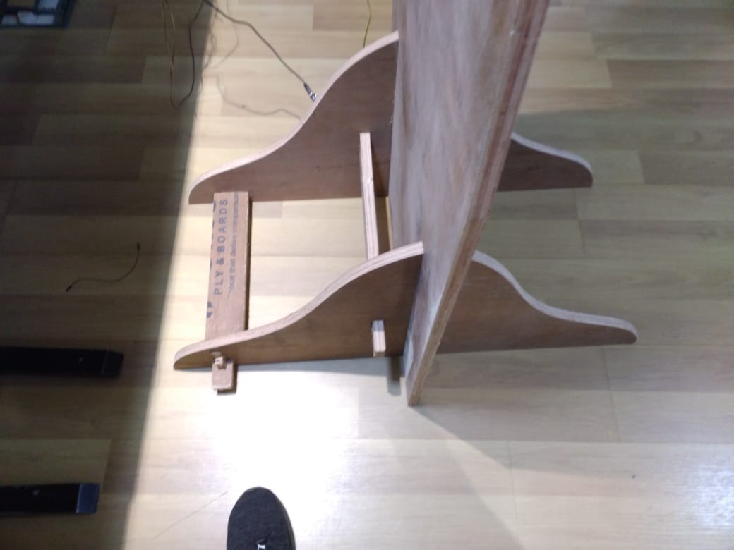
I have altered the base. I was satisfied with its stability

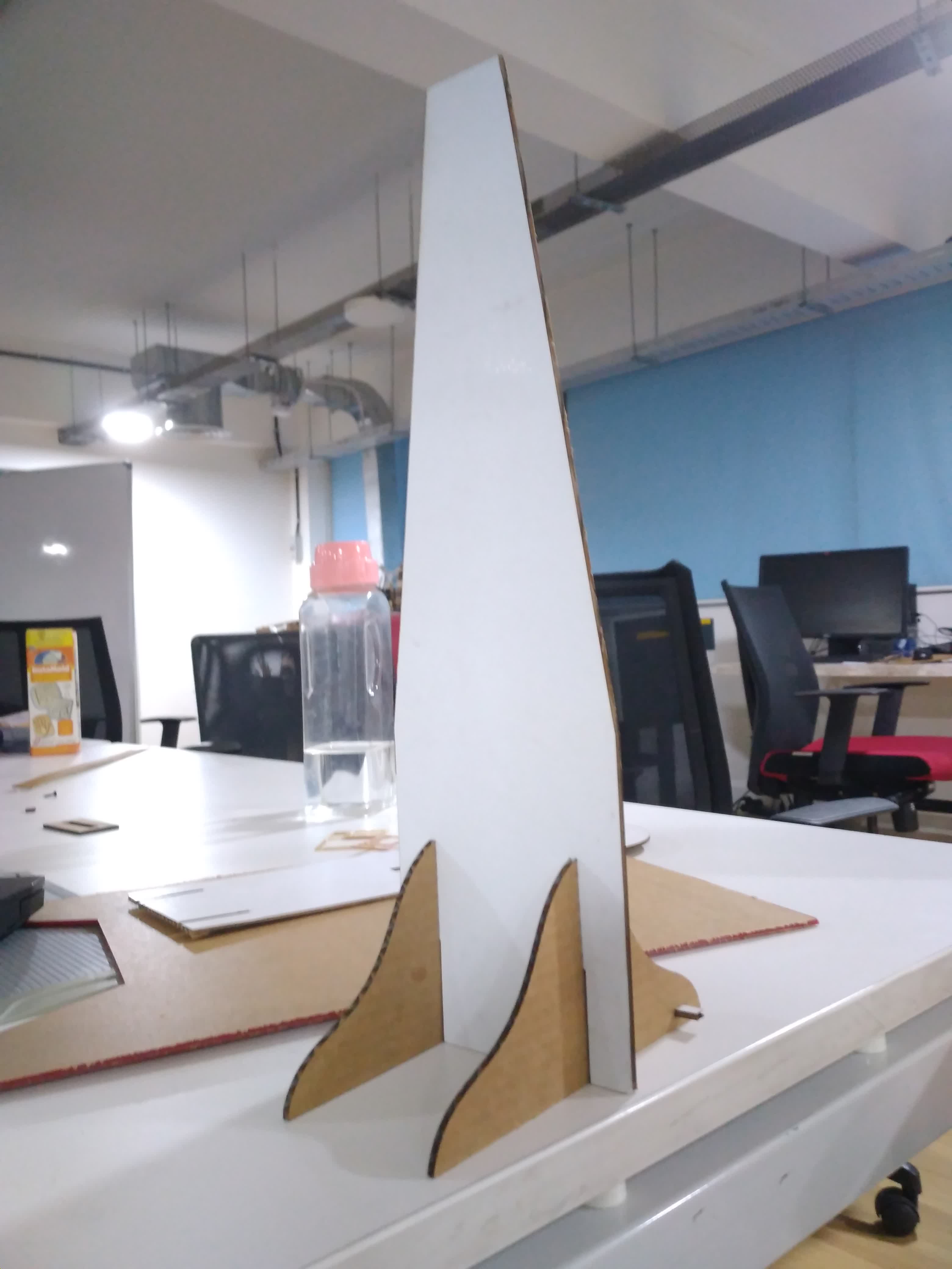
I have filleted it at the top, to reduce the weight
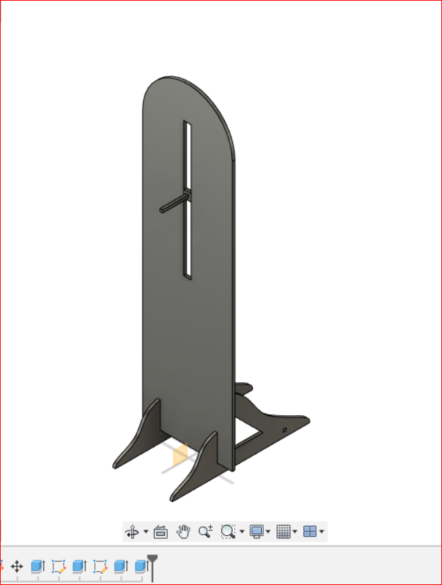
Since, this is a digital height checker, and I am gonna use a ultrasonic sensor, I have realized that I can do away the slot in middle. Further, I chamfered the top for further weight reduction

I have pulled the planck down, for further stability.
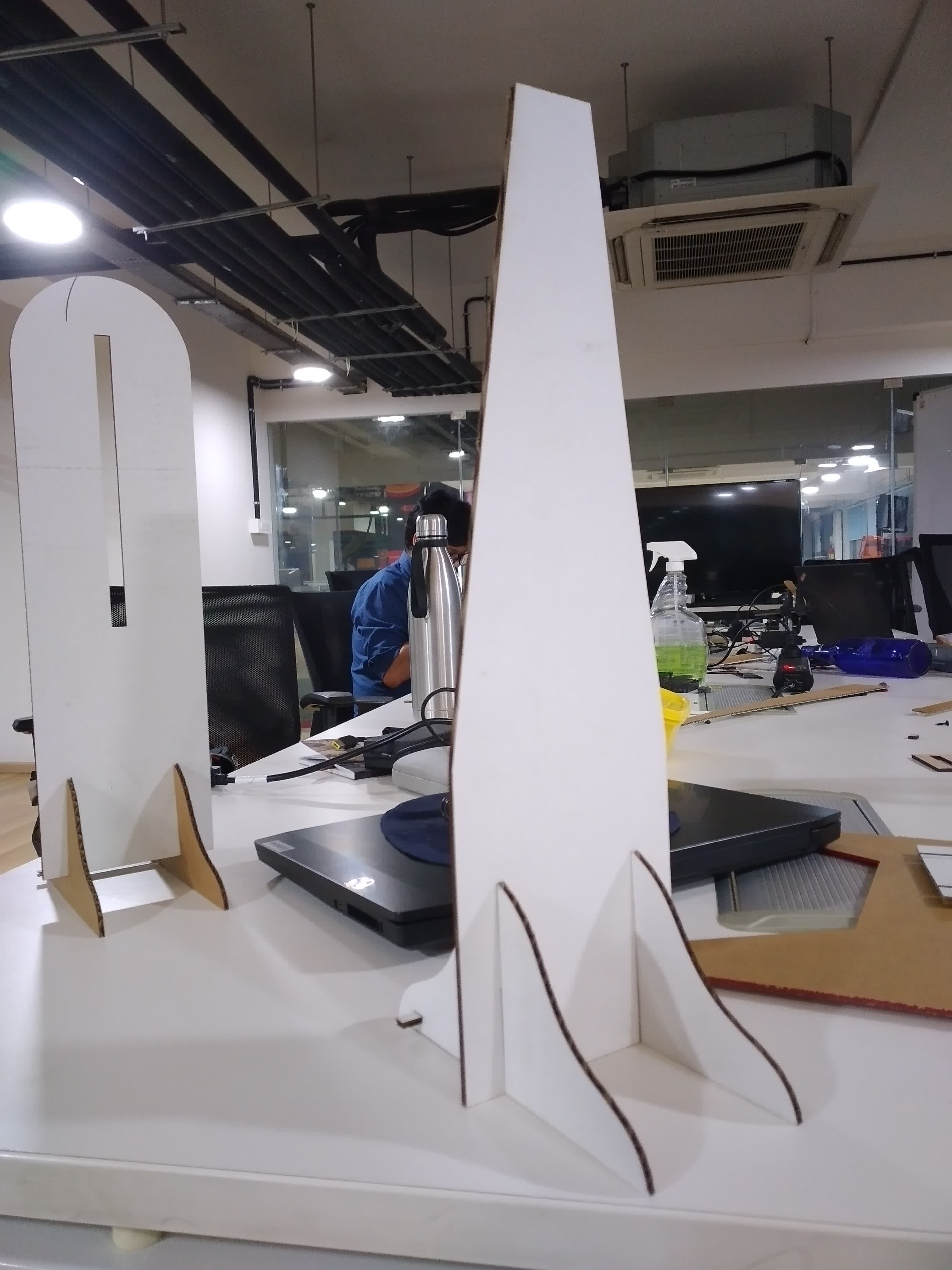
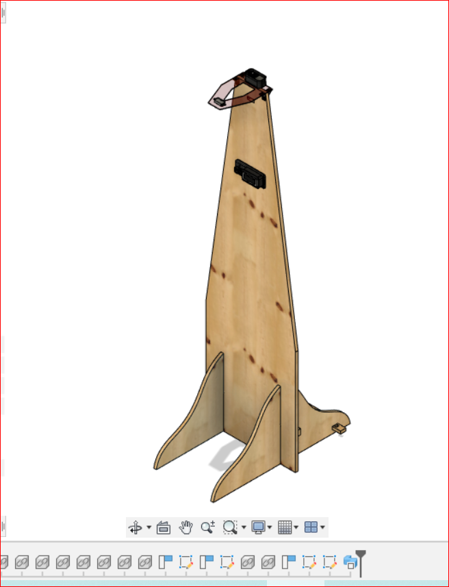
Final Version:
All the iterations, I had to go through:
CNC machining is a subtractive process that uses rotational cutting tools called “end mills” to remove material. An end mill, while similar in appearance to a drill bit, is far more versatile. However, in practice the terms “bit” and “end mill” are often used interchangeably

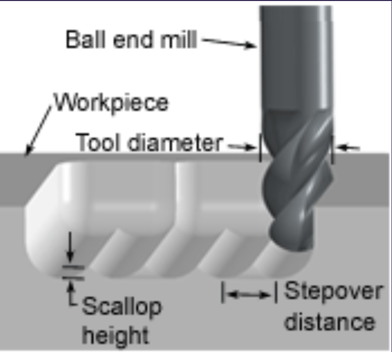
Flat end leaves flat surface profile on the stock and are good for removing large volume of material, but steps are formed when used for making curved surfaces. Ball end leaves curved surfaces and forms smooth curved finish while cutting cavities. They are used for finishing cuts.

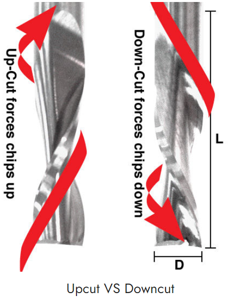
The inner workings of a bit:
In an Upcut type end mill the teeth on the flute will point upwards. This means that the end mill is cutting and drawing out the wood through the flute. This is good for cutting deep into the stock. But this leaves a bad surface finish on the top of the surface. A downcut type end mill has teeth that point downward on the flute. This means that the end mill will cut and try to push the material into the stock. This will give good surface finish on the top, but it is not very efficient at removing material. You can slide over the bit using fingers and differentiate between up cut mill and down cut mills.
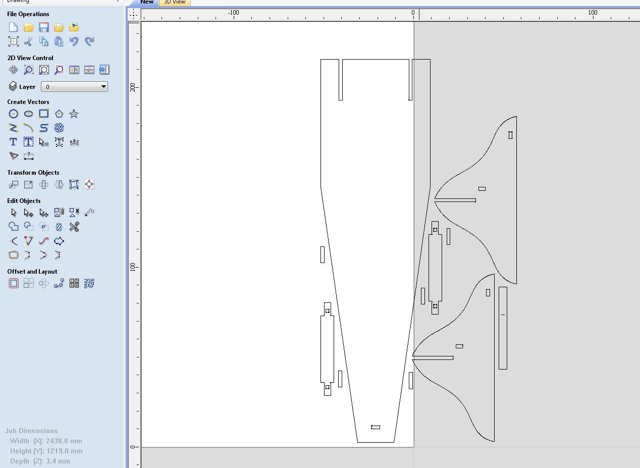
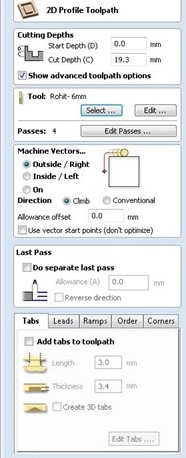
Export the .DXF file created previously, and send it to VCarve software. It will convert your file into G-Codes, which shopbot can use to mill the wood.
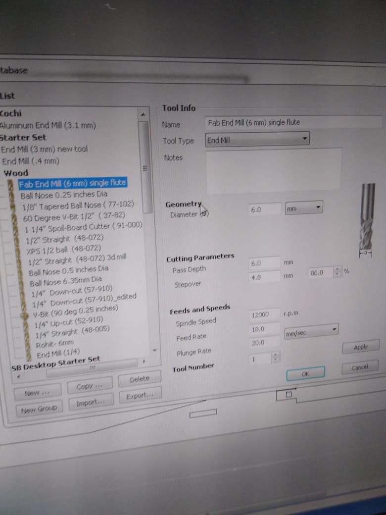
Make sure the bit-size is compatible with the material you are cutting:
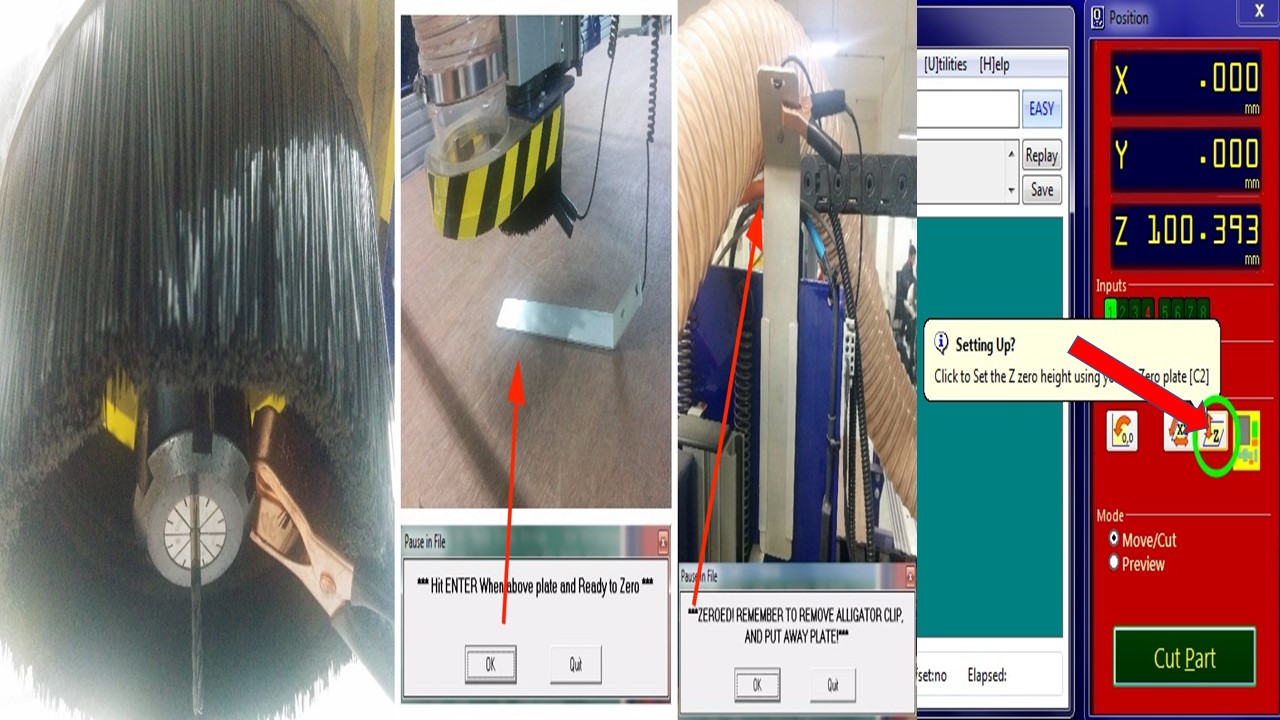
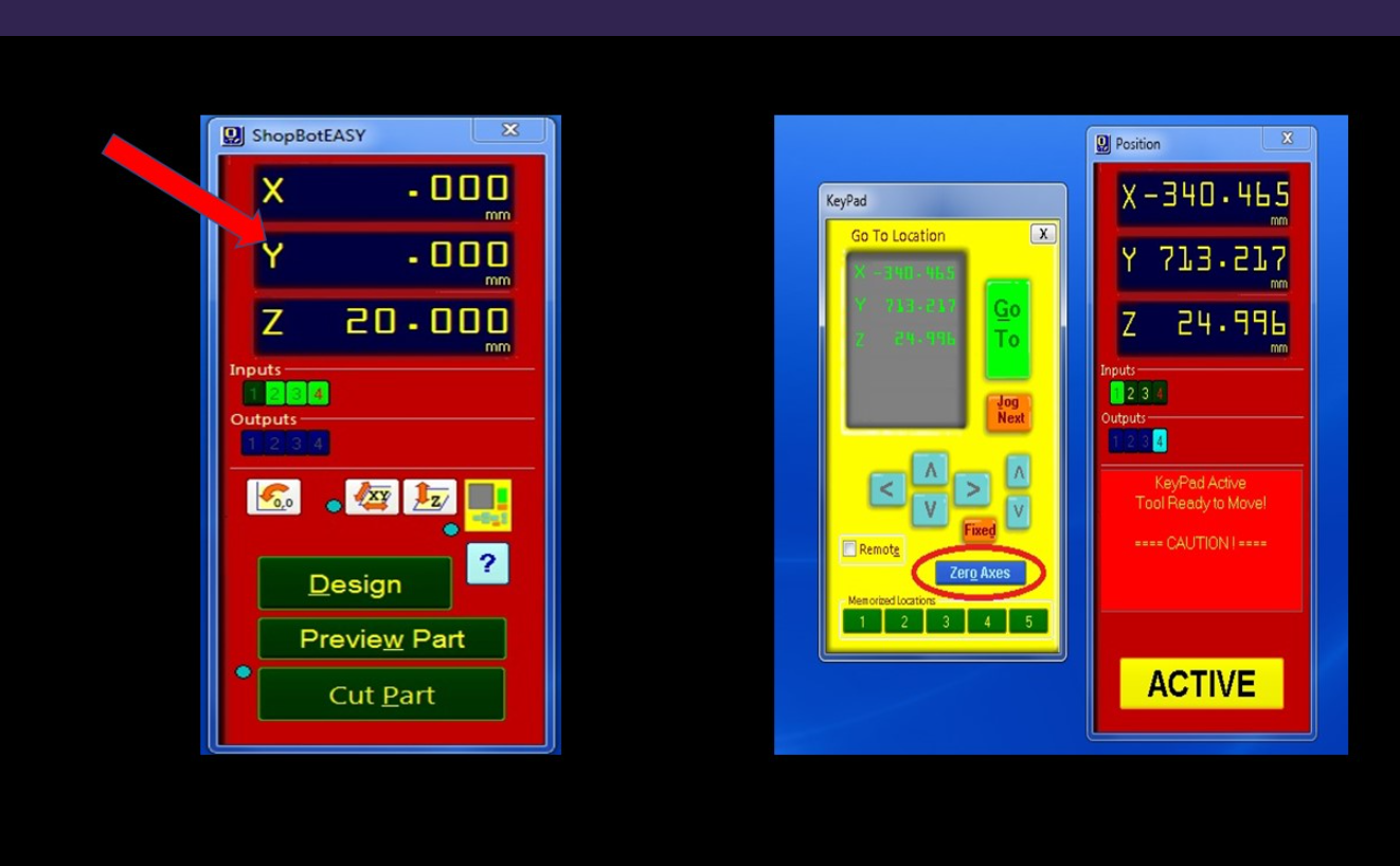
Use keypad to manually choose X and Y co-ordinates, and then click the zero-axis button in the software.
The common time-frame for any shopbot work is from 1-6 hours.


Send the file to cut, using Shopbot Controller Software.

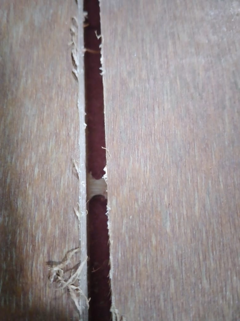

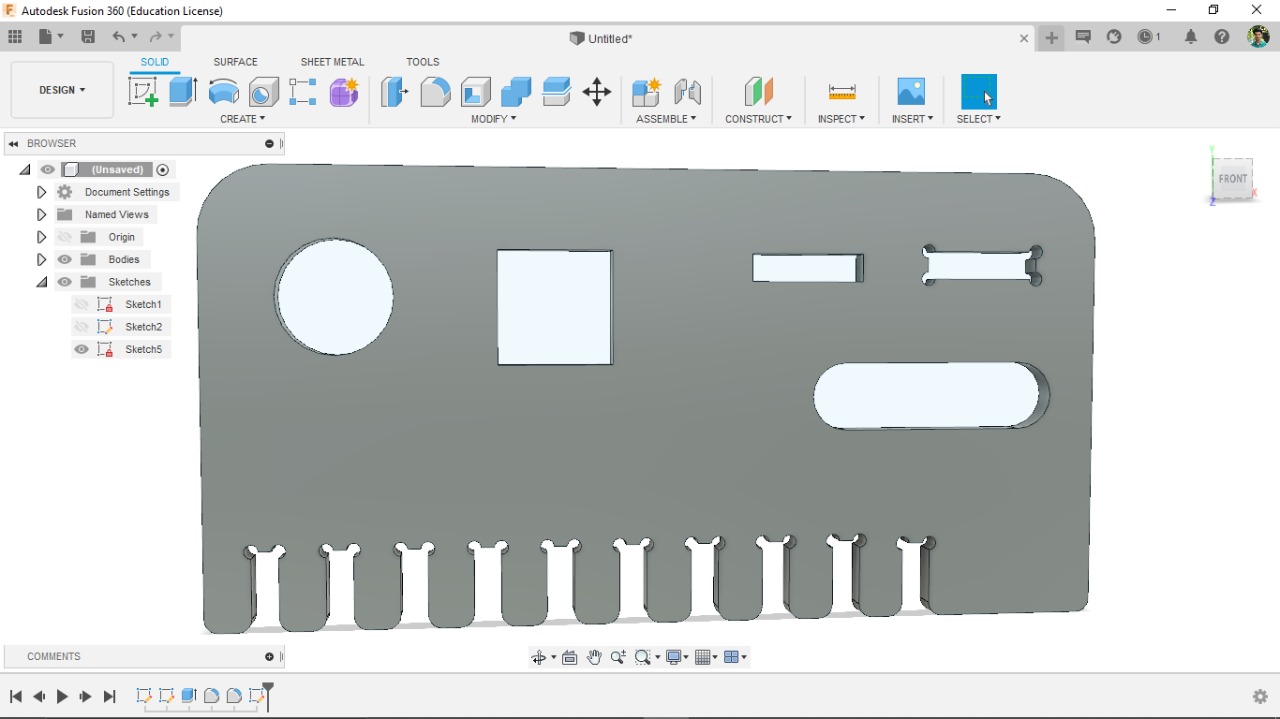
This week We need a test runout, alignment, speeds, feeds, and toolpaths for our machine by part of our assignment. So for testing some parameters in shopbot, we have designed a structure in Fusion 360.

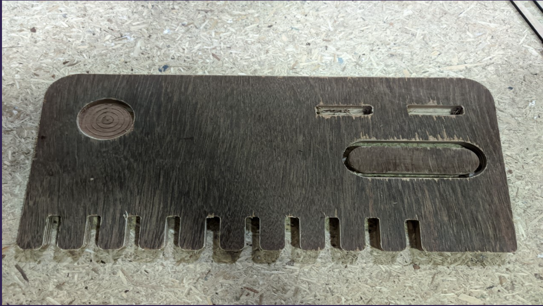
This was our group assignment to find the press fit dimension for the 12mm and 18 mm plywood .So we cut slots from 18.60 to 17.80 in steps of 0.1mm and for 12mm from 11.70 to 12.50 in steeps of 0.1 mm. We found out that the right press fits comes somewhere near 18.6 mm and 12.4 mm. The material thickness does vary a bit with temperature, moisture etc.