WEEK 4 Electronics production
Group Assignment
characterize the design rules for your PCB production process
This week’s group Assignment is written in here
Individual Assignment
make an in-circuit programmer by milling and stuffing the PCB, test it, then optionally try other PCB processes
Our CNC Milling Machine
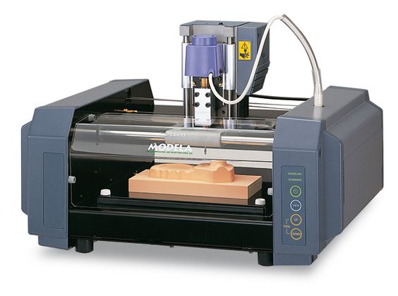
Roland Modela MDX-15
Work Area: 52.4 x 101.6 x 60.5 mm
OS:Ubuntu
Software:Fabmodules
Tools
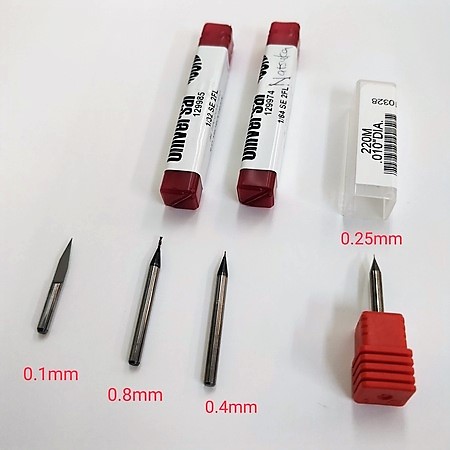 Milling bits
I used two kinds of the image above.
Milling bits
I used two kinds of the image above.
For traces
-0.0156” DIA 2FL SE AlTiN
1/64 Inches(0.396875 mm)
For interior
-0.0312” DIA 2FL SE AlTiN
1/32 Inches(0.79375 mm)
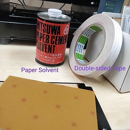
Other Tools
-Paper solvent
-Double-sided Tape
-FR1 PCB(カット基板 銅張積層板 片面 紙フェノール 100×150×1.6mm【NO12】)
Generating tool path
To generate tool path and send to machine, I used fabmodule(CAM software).
Please refer the images below for the settings.
hello.serial-UPDI.3
USB-FT230XS-serial
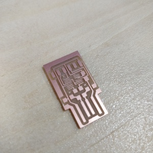
Milling
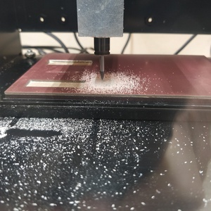
First time it didn't work because of the way I set the mills.
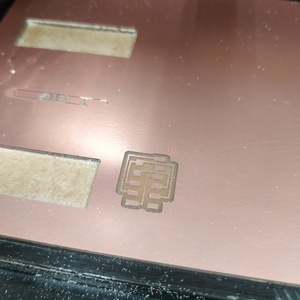
Traces with 1/64 bit
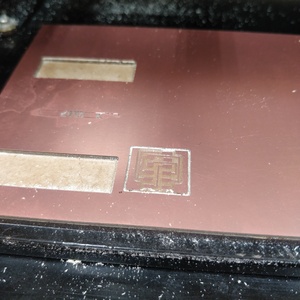
Interior with 1/32 bit
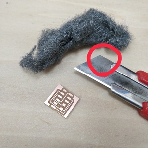
File on the back of cutter and files to smooth the surface.
Same steps to USB-FT230XS-serial too.
Problem
First time although CNC milling machine moved correctly, it engraved notthing.The reason was the way I attached the milling bit. I was too afraid of breaking it and couldn't set it close enough.The tip of endmill wasn't touched to the surface of PCB.
I tried to attach bit again and it worked right second time.
Soldering
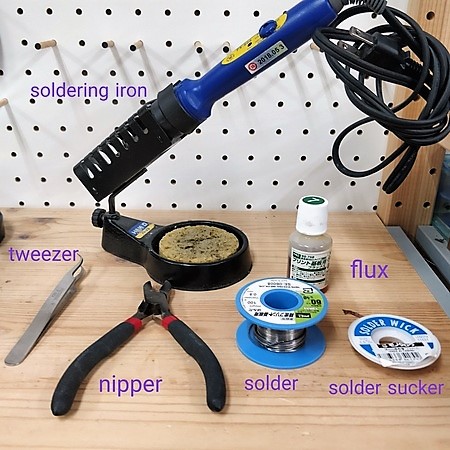
Those are tools we need for soldering.
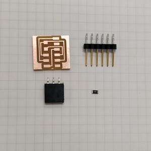
Components for hello.serial-UPDI.3
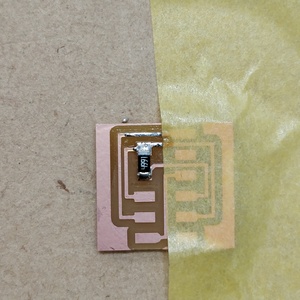
Fix the board with tape so that it doesn't move while soldering
Inside to outside, small component to big compornent.
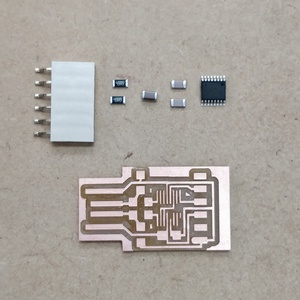
Components for USB-FT230XS-serial
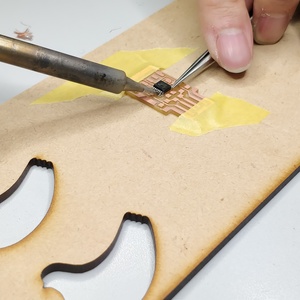
Use tweezers for tiny parts.
Check with the multimeter.
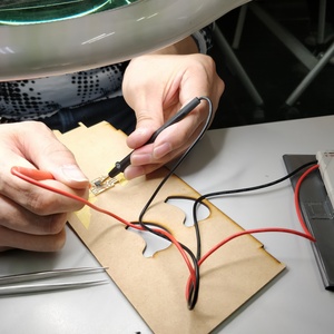
Function Check
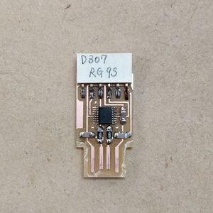
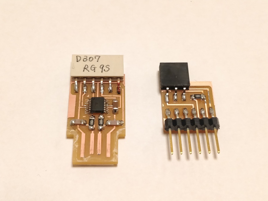
Mark GND and write down the name of PCB with parmanent marker to prevent confusion of connecting
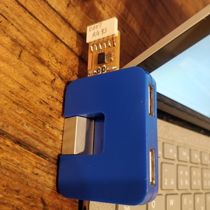
Connecting with my PC
*I colored GND with red marker, but after that I learned that color of GND is typically black. If red, we misunderstand the pin is power(5V, etc).
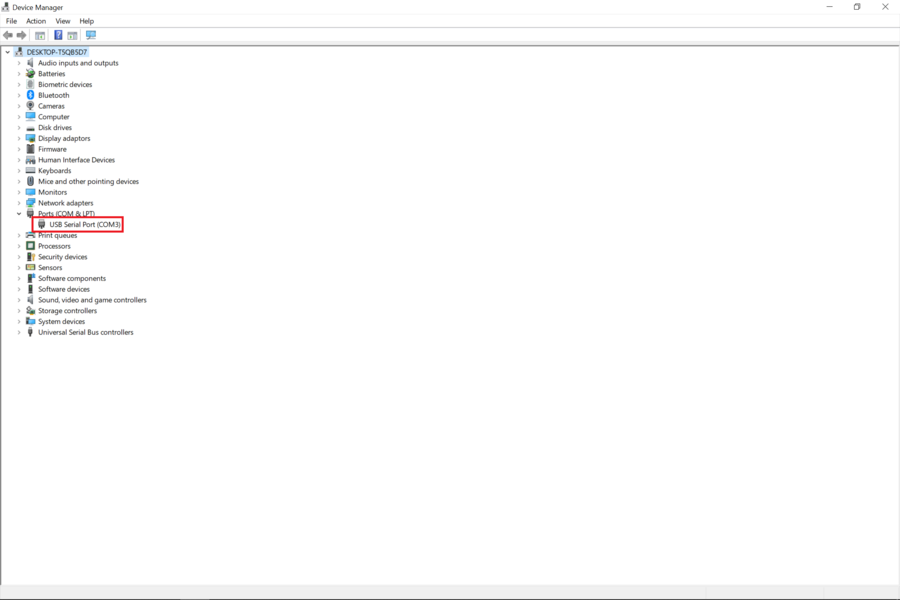
For Windows
From the device manager.
(Press {Windows}+{X} to open device manager)
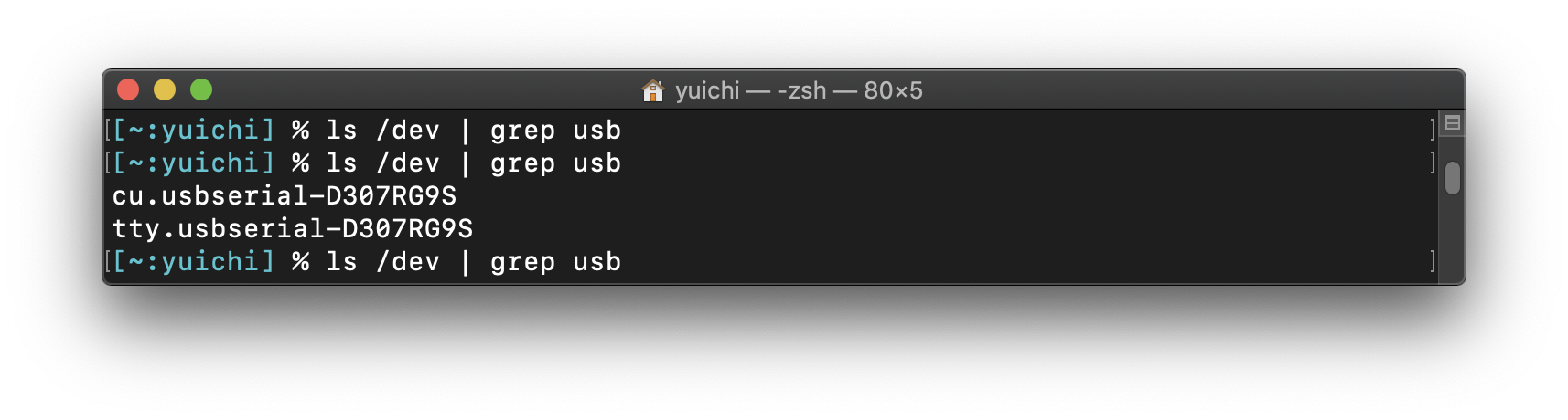
For mac
Use this command.
$ ls /dev | grep usb
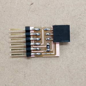
Hero shots
Thoughts
-Soldering was tough..I need to practice more.If I have mistake, trying to remove solder with solder wick in early stage make the situation better.
-3 pin UPDI can make stable connection to PC through USB.
Written by Natsuka Kamei 亀井 夏香