WEEK13 Output Devices
Group Assignment
measure the power consumption of an output device
Individual Assignment
add an output device to a microcontroller board you've designed,
and program it to do something
My Idea
I'm planning to use several servo motors for my final project automatic-sake-pouring machine.
The structure is as follows:
1. Detect the weight of remaining liquid in the cup by loadcell sensor.
2. If the weight is light, rotate the top table 360 degree of x and y axis by the servo motor1 to move the right drink to front of appropriate user.
3. Rotate the drink holder 135 degree of z axis by the servo motor2/3/4 and pour liquid in the bottle to the bamboo tube.
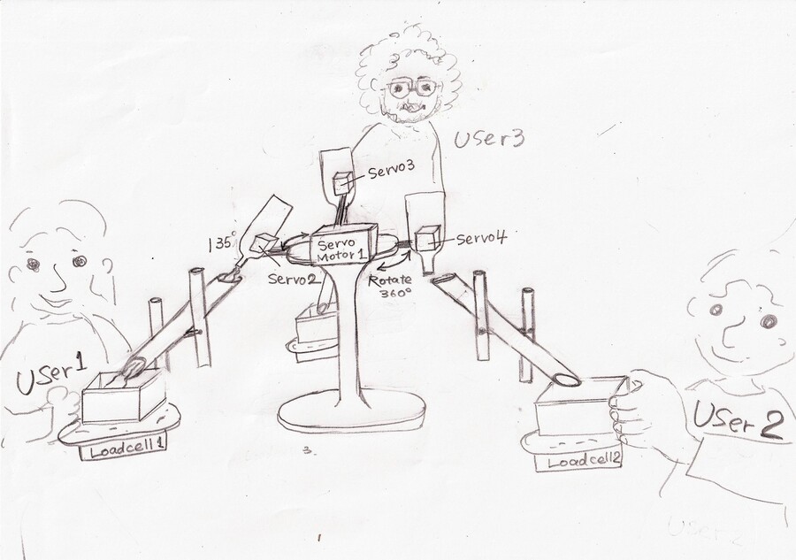
(For the detailed structure please refer to my final project page.)
I've already made the weight sensor with load cell on week 11 Input Devices class, so this week I tried making output devices. For trial, I decided to make only servo motor 2(as noted above).
I was thrilled to make another self-made device for my final project and felt like I was getting closer to finishing my final project…!(Still long long way to go, though)
Making the connection part with the servo
To test the moves of the servo motor, I needed to think how to connect the servo motor with the sake bottle.
I came up with the simple structure like this.
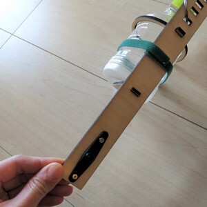
For designing data I used Fusion 360 because I needed to make it parametric in case of changing the materials for the holder.(4mm plywood for this time)
This time it's just trial to check the moves of servo motor so I made minimum nesesarry design for the holder, but I am excited to brush up it for the final project.
Testing the Servo with the breadboard
The first thing I tried on the local session was testing the servo motor with the breadboard.
This helped me to understand the connections.
For the program I used the sample program from Arduino.
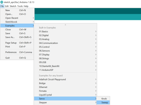
    /* Sweep
 by BARRAGAN
 This example code is in the public domain.

 modified 8 Nov 2013
 by Scott Fitzgerald
 http://www.arduino.cc/en/Tutorial/Sweep
*/

#include

Servo myservo;  // create servo object to control a servo
// twelve servo objects can be created on most boards

int pos = 0;    // variable to store the servo position

void setup() {
  myservo.attach(16);  // attaches the servo on pin 16 to the servo object
}

void loop() {
  for (pos = 0; pos <= 180; pos += 1) { // goes from 0 degrees to 180 degrees
    // in steps of 1 degree
    myservo.write(pos);              // tell servo to go to position in variable 'pos'
    delay(15);                       // waits 15ms for the servo to reach the position
  }
  for (pos = 180; pos >= 0; pos -= 1) { // goes from 180 degrees to 0 degrees
    myservo.write(pos);              // tell servo to go to position in variable 'pos'
    delay(15);                       // waits 15ms for the servo to reach the position
  }
}
Then, it worked!
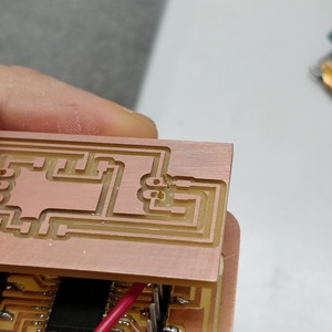
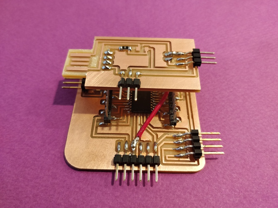
Designing the board
Next thing I did was making own board for the servo.
I've made ATtiny3216 on week11, so decided to make connection board with it this time.
I added the vertical pin headers on ATtiny 3216, so the connection board should have the holes to penetrate them and come on the top of ATtiny3216.
Tips to make the holes on the board
I followed the instruction by my instructor Tamiya-san, to make the holes on the board easily.
1.Assign the shortcut key from "Option"tab>"Assign">"NEW" on EAGLE.
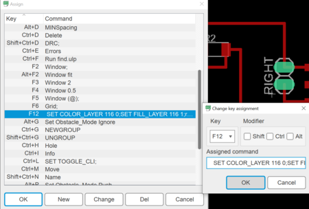
2.On the New shortcut view, select the key as you like for "key".Add as follows for "assigned command".
SET COLOR_LAYER 116 0;SET FILL_LAYER 116 1;run drill-aid 0
3.Use the shortcut key you created when you would like to make the holes.
4.For exporting PNG files to mill, chose two layer, "116.centerDrill" and "48.Documents".
Then you can mill the outline and holes in same time!
Milling and Soldering
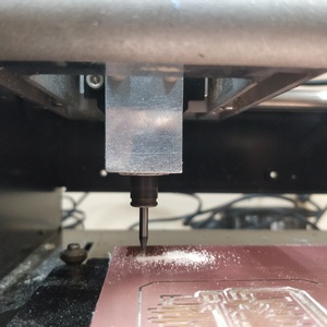
As usual, I had a few problems this week.(I have been getting accustomed to encounter the problems every time...)
Problem1 THe position of the holes
I tried to connect two boards as soldering but found out there was error for the position of the holes.
The reason was that I miscalculated the position of holes at the designing stage...
Time passed so fast ,it was getting late, I was getting tired and at a loss.
Then my insrtuctor lent me this amazing electric drill!
Mistake
Electric drill
It fitted!
Problem2 Soldering mistake
I used another item to fix missoldering problem. It was soldering sucker with spring action.
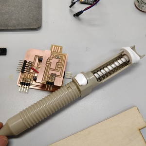
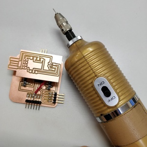
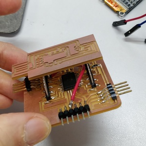
With many helps with magical items,finally my two-storied PCB board was completed.
Hero Shots
Testing the Servo With the PCB board
For the programing, I used same one as testing with the breadboad.This time I put water into the bottle and checked how it works for my final project. Water spills too vigropusly so I will need to adjust my program well for my final project...
<
Thoughts
-At first I was afraid of the classes about electronics ...but now I'm getting hooked on it! Watching the moves of the things I made actually is really exciting.
-The power supply was the carried-over issure.This time I used USB from PC for the power supply. I tried the external power supply but didn't work for some reason.
As considering I will use several servo for my final project, It's for sure that need the external power supply not USB.The investigation of the error is necessary by the next time.
Files
Servo board design data(EAGLE) sch brd
Servo board design data(EAGLE) Top Outline&holes