Week 18: Project Development
As of this date 06/21/2021 the completed tasks are:
- Internal frame
- Case
- Mecanum wheels
- IMU
- Closed loop motor controller
- IMU
- Motor controller firmware
- ROS package
- Web interface
- Navigation and mapping
At the moment everything mentioned above as completed is working.
During the development process many problems emerged, the first, the most frustrating and most complicated were the motors, initially I had ordered some motors that met the requirements I needed even I ordered them well in advance, but there was a problem and that was that the engines were never sent and the company did not update the tracking and did not notify the status of the package, after contacting them they replied that they would send them again with another shipping company, I waited for a week for updates and when I returned to contact them they replied that they would return all the money, after this huge loss of time they caused me there was a month left to present the project and I had to look for new motors which was very difficult because I did not have much money to buy motors that met the specifications, so in the end I bought some small motors that did not have all the required specifications, all this so that one day before presenting the project a motor failed, a tooth of the gear broke which prevented the motor to turn and it simply blocked.
The problem with the motors has yet to be solved in order to fully test the system, spare motors are now in place but need to be wired.

I have learned a lot during the development process, at the same time I have strengthened my skills in PCB design and fabrication, programming, 3D design, interfaces and communication and many other things.
The system is composed of different components as shown in the following picture

In the demo video you can see a PS4 controller that is not part of the system and was being used only to test the operation, but essentially it is a bluetooth device connected to the Raspberry Pi, in the ROS package there is a python script to publish the control information in "/cmd_vel" that controls the motors. Below is the code that publishes the PS4 Controller information and the Motor Driver code which subscribes to "/cmd_vel" and it is sends that information via serial communication from the raspberry to the Motor Controller.
joy_controller.py code
                                #! /usr/bin/env python
                                import rospy
                                from geometry_msgs.msg import Twist
                                from sensor_msgs.msg import Joy

                                # This ROS Node converts Joystick inputs from the joy node

                                def callback(data):
                                    twist = Twist()
                                    twist.linear.x = 1*data.axes[5]     # right joystick up/down [full up 1, full down -1]
                                    twist.linear.y = 1*data.axes[2]     # right joystick right/left [full right -1, full left 1]
                                    twist.angular.z = 1*data.axes[0]    # left joystick right/left [full right -1, full left 1]
                                    pub.publish(twist)

                                # Intializes everything
                                def start():

                                    # starts the node
                                    rospy.init_node('joy_controller')
                                    rospy.loginfo("Joy Controller node started")
                                    rospy.loginfo("Subscribing /joy and publishing /cmd_vel topics")

                                    global pub
                                    pub = rospy.Publisher('/cmd_vel', Twist, queue_size=10)

                                    # subscribed to joystick inputs on topic "joy"
                                    rospy.Subscriber("joy", Joy, callback)

                                    rospy.spin()

                                if __name__ == '__main__':
                                    start()
motor_driver.py code
                                #! /usr/bin/env python
                                import rospy
                                import serial
                                import numpy
                                import time
                                from geometry_msgs.msg import Twist

                                L1 = 0.18 # meters - distance between left and right wheel divided by 2
                                L2 = 0.175 # meters - distance between front and rear wheel divided by 2
                                R = 0.078 # meters - wheel radius (not used)

                                A = [[1, 1, -(L1 + L2)],
                                    [1, -1, (L1 + L2)],
                                    [1, -1, (L1 + L2)],
                                    [1, 1, (L1 + L2)]]

                                vx = 0
                                vy = 0
                                theta = 0

                                B = [vx, vy, theta]

                                result = [0, 0, 0, 0]

                                def callback(data):
                                    global vx, vy, theta, B, A, result
                                    twist = Twist()
                                    vx = (data.linear.x)
                                    vy = (data.linear.y)
                                    vz = (data.angular.z)

                                    print(data.linear.x)

                                    B = [vx, vy, theta]
                                    result = numpy.matmul(A, B)
                                    # print(result)
                                    serialport.write(str(int(result[0]*100*-1)).encode() + "\n".encode())
                                    serialport.write(str(int(result[1]*100*-1)).encode() + "\n".encode())
                                    serialport.write(str(int(result[2]*100*-1)).encode() + "\n".encode())
                                    serialport.write(str(int(result[3]*100*-1)).encode() + "\n".encode())


                                def main():

                                    global serialport
                                    serialport = serial.Serial('/dev/ttyACM0', baudrate=9600)  # open serial port
                                    rospy.loginfo("Serial comunication")

                                    # starts the node
                                    rospy.init_node('robot_base')
                                    rospy.loginfo("Robot Base node started")

                                    rospy.Subscriber('/cmd_vel', Twist, callback)

                                    rospy.spin()

                                if __name__ == '__main__':
                                    main()
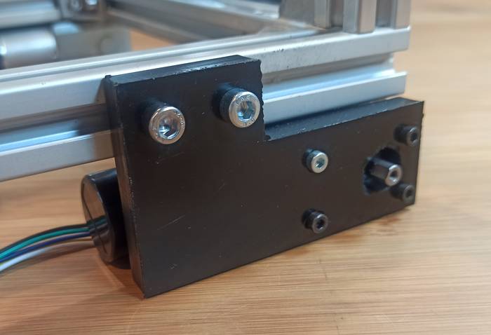
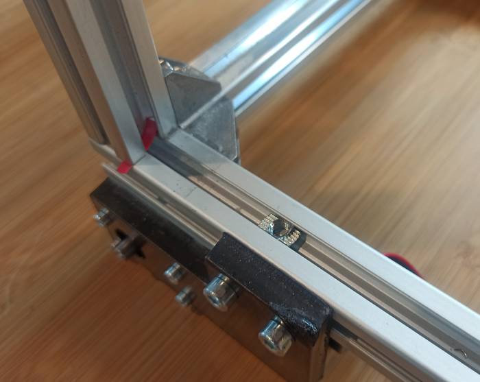
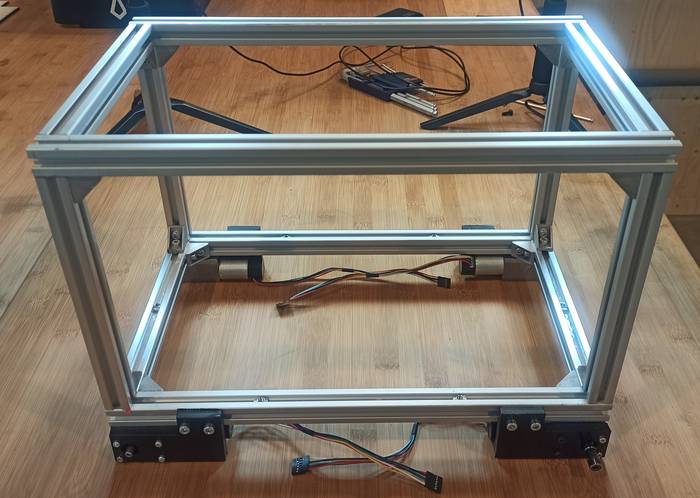
The development of the robot started with the design of the internal frame, the idea of having an internal frame is to give rigidity to the robot since it is intended to be a robot to carry heavy objects.
The dimensions of the internal frame correspond to 40x25cm using aluminum profiles.
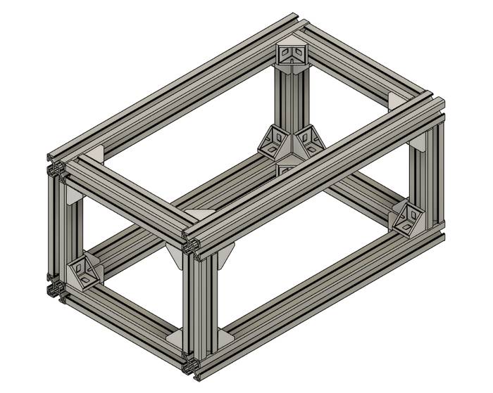
The 3D model of the interior is mainly to have a visual reference of the interior and use it as a reference and compare proportions with other objects, also then you must design a case that will be placed on top of it.
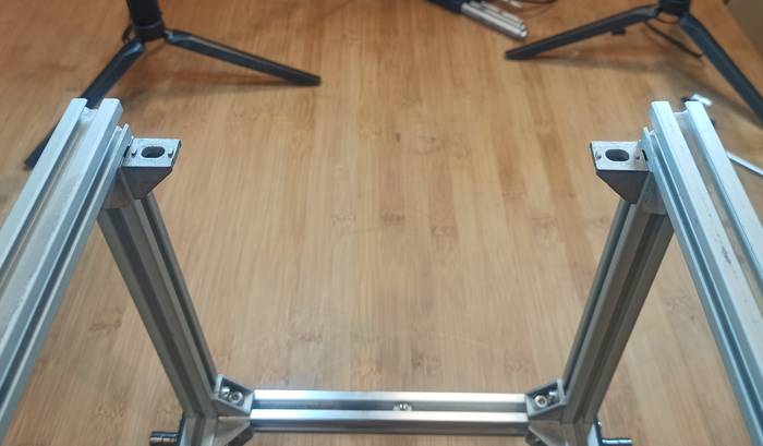
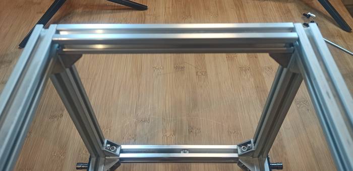
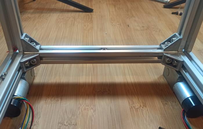
To make the frame I am using 20x20mm aluminum profiles, M5 screws and brackets with T-nuts.
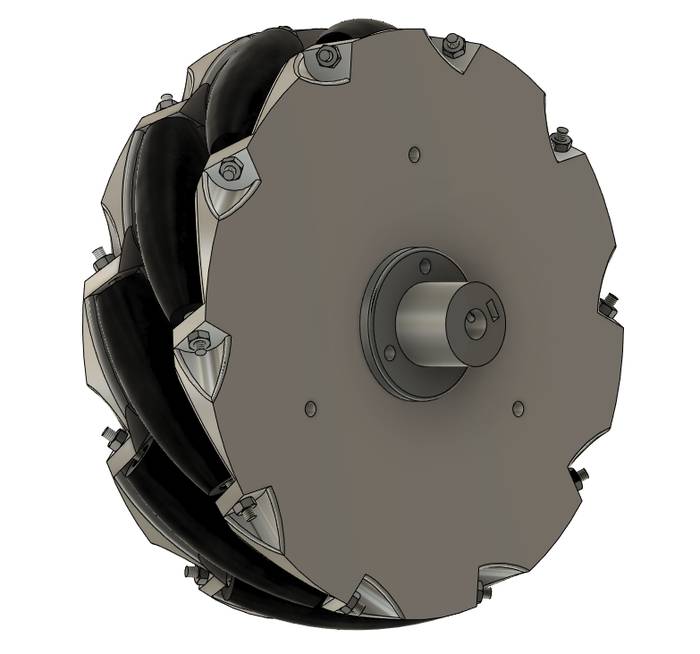
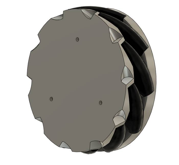
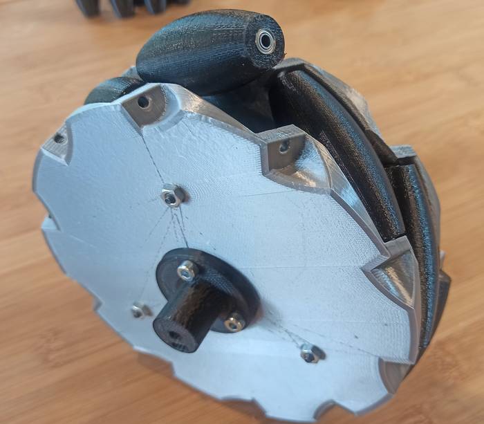
The next step was to design the mecanum wheels that will be used by the robot, I decided to make the wheels myself due to the high cost of 4 wheel kits of this type.
The dimensions I wanted to achieve in this design are equal to the standard 6 inch wheels on the market equivalent to 152.4 millimeters.
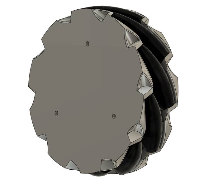
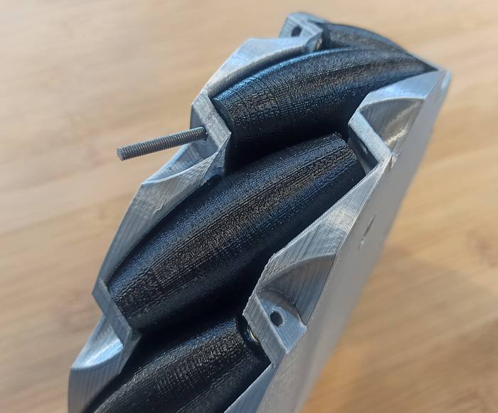
The design starts by delimiting a set of construction planes that allow to create a roller with exactly 45 degrees of inclination.
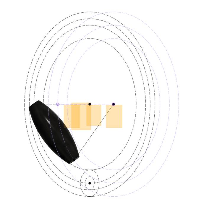
Then a circular arrangement is applied.

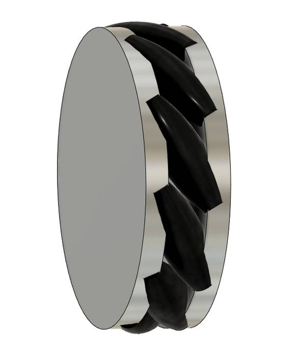
The design of the side of the wheel looks like this, and as shown in the image the rollers are intersected with the side, they need to be shaped like this to subtract them from the side.
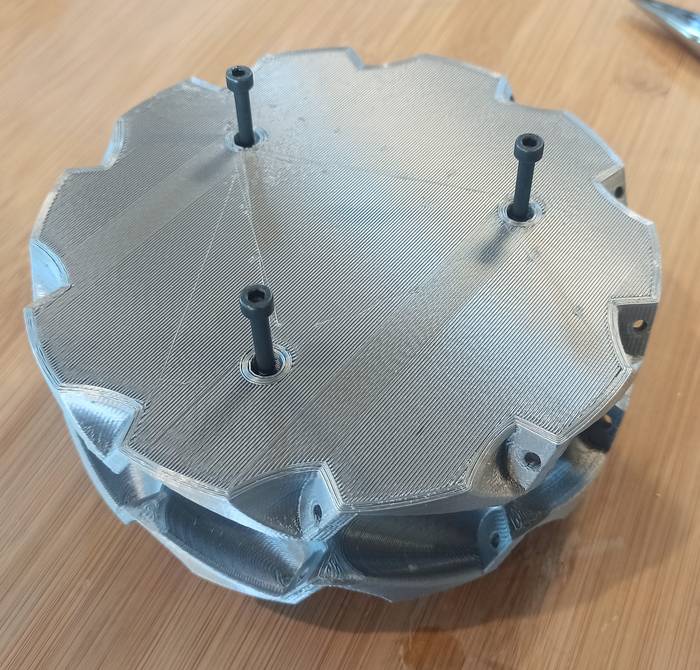
By creating a plane at the end of the roller, the support points for the rollers are created as shown below.
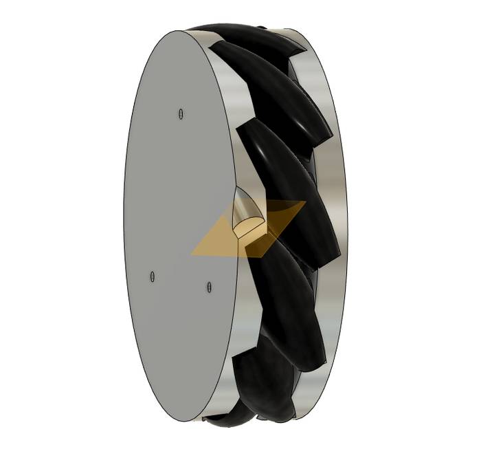
A circular arrangement is used to create the support points on the contour.
Now the intersection with the rollers is subtracted from the side parts.
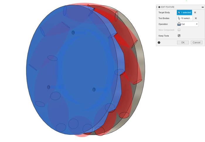
Some Fillets are applied.
Finally the holes for the axes of each roller are created.
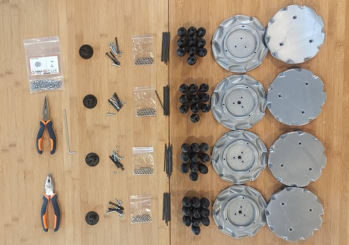
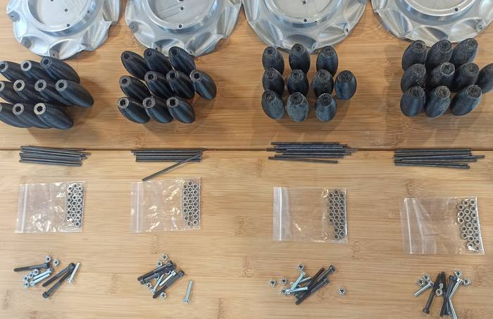
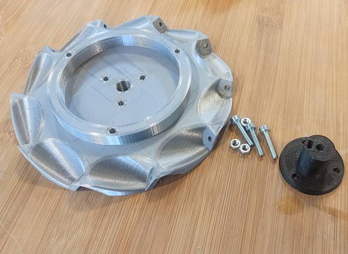
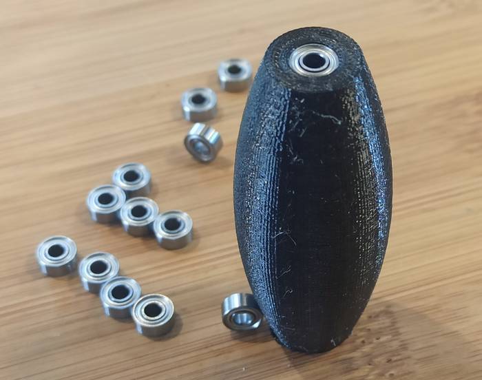
Each wheel consists of:
- x10 Rollers
- x20 683ZZ bearing (x2 each roller)
- x20 Nuts DIN 985 M3 (x2 each roller)
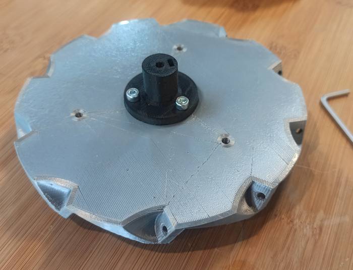
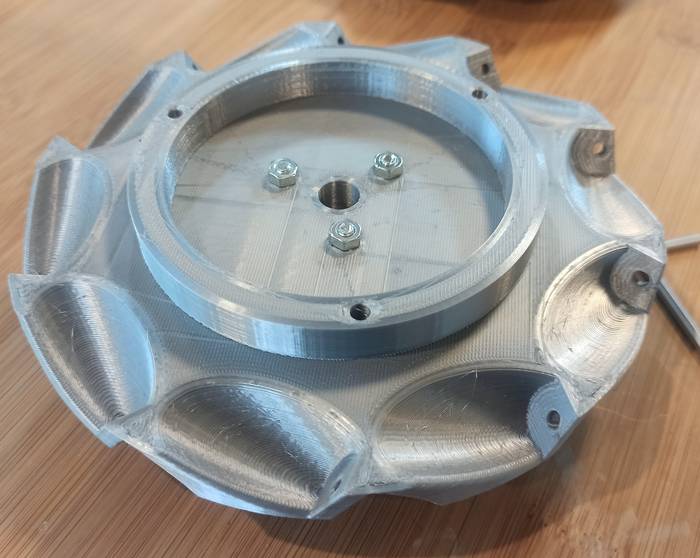
- x3 Screws M4 x 60mm
- x3 Nuts DIN 934 M4
- x10 Threaded rod M3x70mm
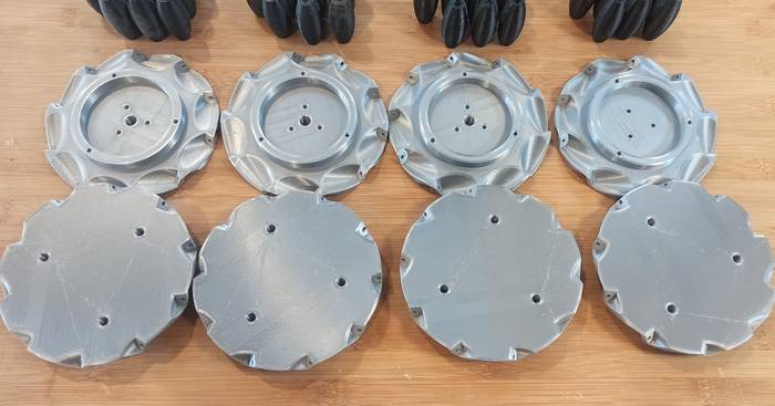
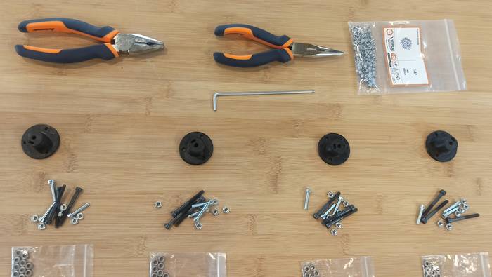
- x2 Printed parts
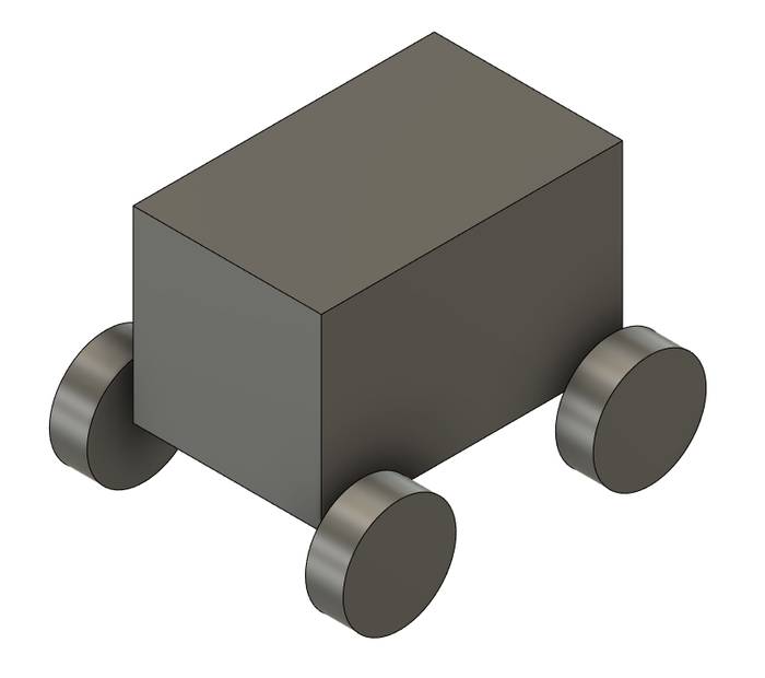
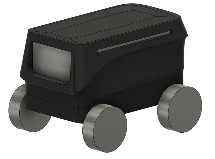
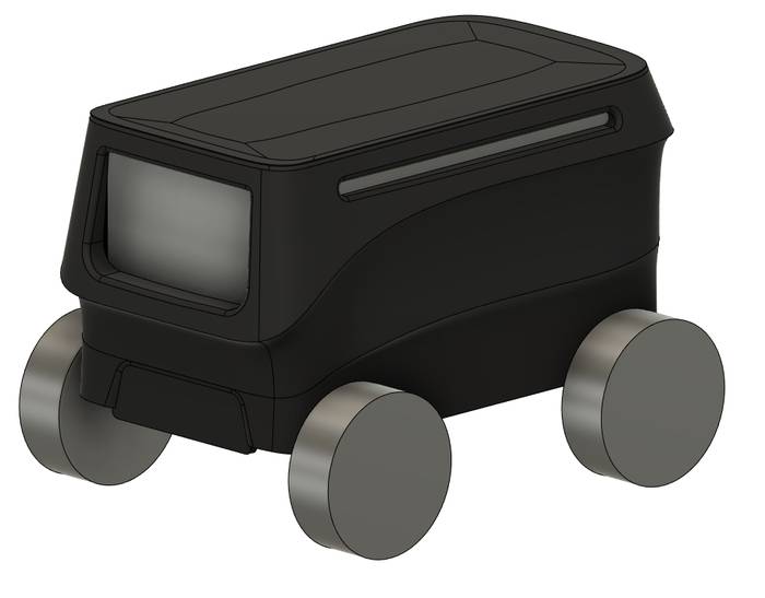
For the design of the case of the robot I start by creating a rectangle and four cylinders that serve as a reference for the dimensions of the internal frame. I did not use the internal frame design to keep the case file with few components which makes Fusion 360 run more smoothly.
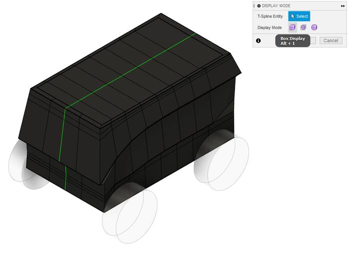
For the case design I used the "Form" workspace in Fusion 360, this is a bit complicated workspace to use at the beginning but personally I have some experience designing objects in it. My way of working is first to use the "DISPLAY MODE"->Box Display to see the shape and make sure that all the sections are ok, something important to keep in mind in this workspace is that triangles damage the geometry of the body, so you have to have squares all over the surface.
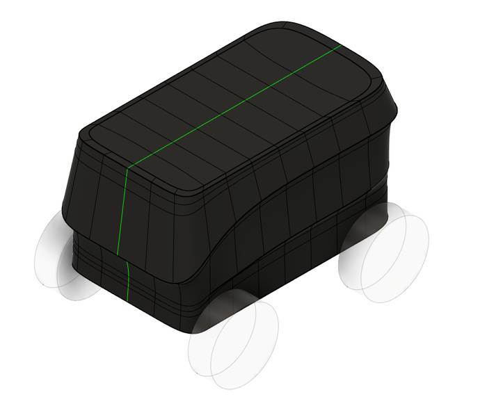
After a long time adjusting everything as there is no precise way to do it and more a process like sculpting I change the view to make sure I'm getting what I want.
At this point the Case of the robot is simply a surface for Fusion 360 so to be able to apply instructions and other operations it is necessary to add a thickness that turns it into a body.
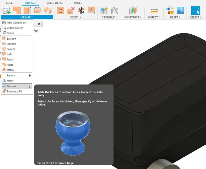
To apply thickness to a surface, go to the surface tab and select "Thicken". This creates a body from the surface.
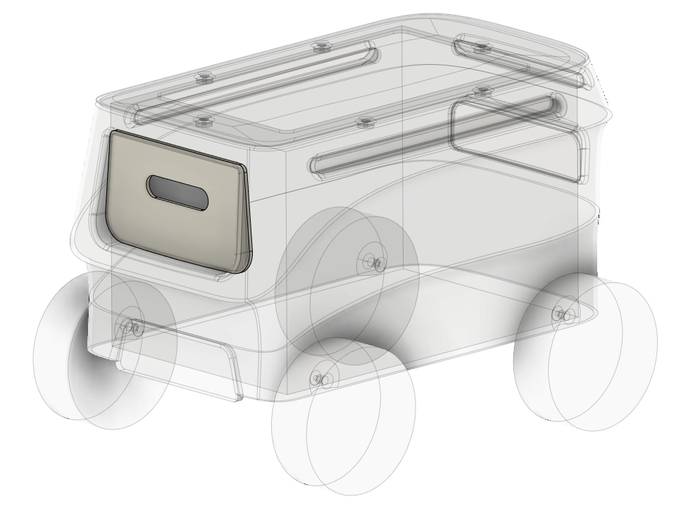
Now it is a matter of creating some construction drawings to make the external parts of the case.
After that I applied some fillets to round some edges.
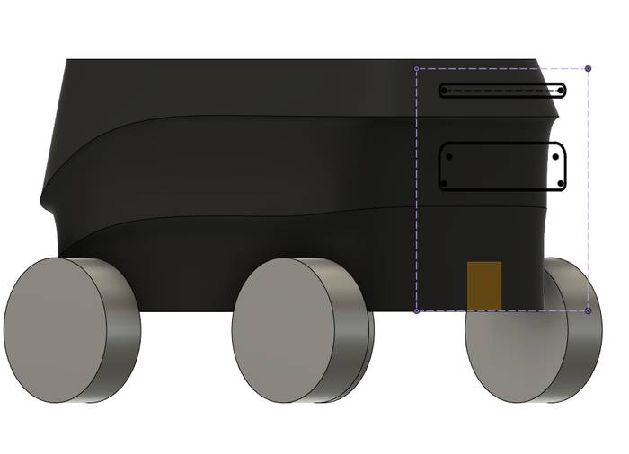
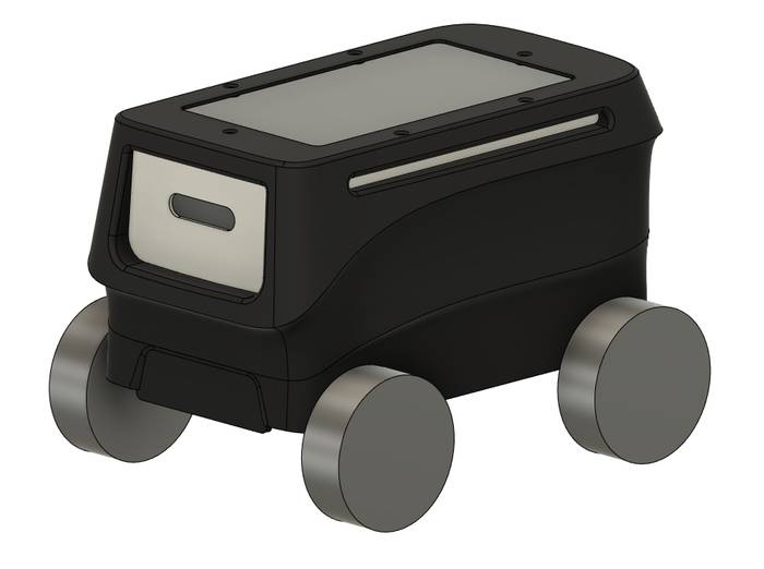
The process of creating the plates is the same for all of them. Simply create a sketch on the inside surface of the case and project the shape, then apply the extrusion and add the details.
The final result is as follows.
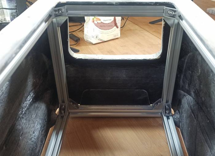
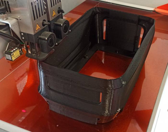
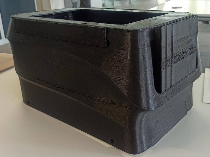
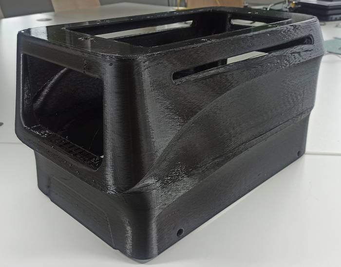
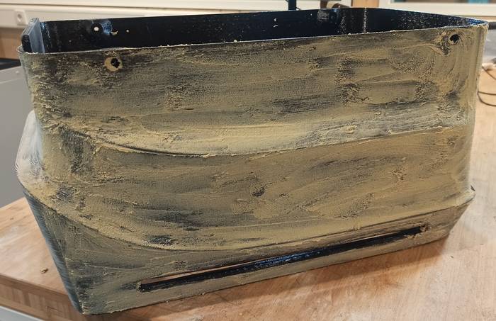
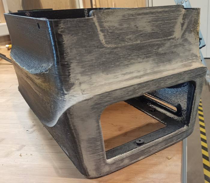
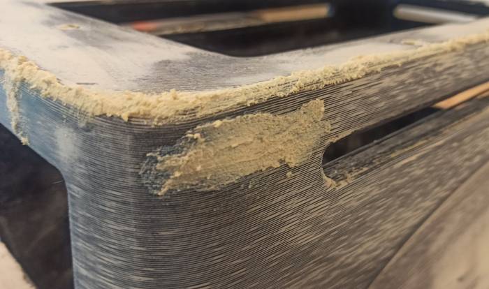
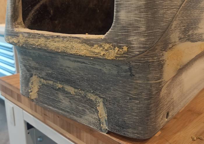
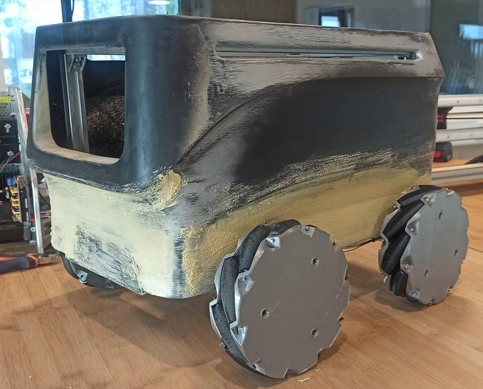
The robot case was 3D printed on a BigRep ONE printer but the printing quality does not produce a finished surface so it was necessary to apply Wood Filler and sanding, repeat this process many times until a smooth surface was achieved, then a primer was applied and finally it was painted.
You can find the process of the IMU in this page
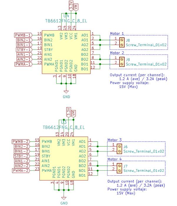
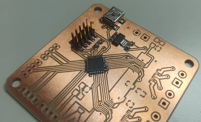
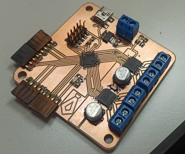
I was very clear that I wanted to make a closed loop controller for the four motors with encoders. The first step in this process was to select the drivers for the motors, I had already designed the Fab Motor Controller using the L298N driver but I wanted to make something more compact so I looked for similar alternatives and found the "TB6612FNG,C,8,EL" which is cheaper and uses "Power MOSFET" so it does not require a heat sink like the L298N.
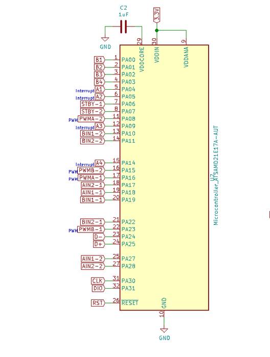
With the driver selected (TB6612FNG,C,8,EL) now it was time to select a microcontroller that had enough pins to control everything, or else use two microcontrollers that communicate with each other by some protocol. Fortunately I had available to use the SAMD21E17A with 32 pins including Interrupts for the encoders and PWM for the drivers so it is a perfect solution.
Having selected the two most important components like the Driver and Controller I could now start designing the circuit, for that I used KiCad.
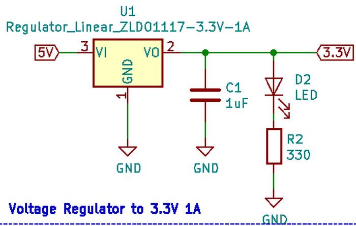
Like my previous designs the schematic is composed of different sections, the first one is the voltage regulator since the SAMD21E17A works at 3.3V.
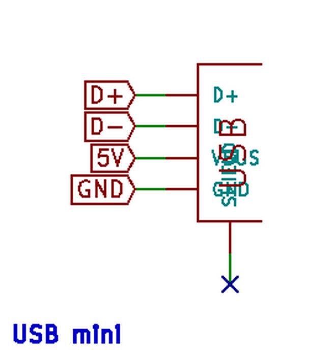
To program and debug the programs I added a USB Mini B connected in this way.
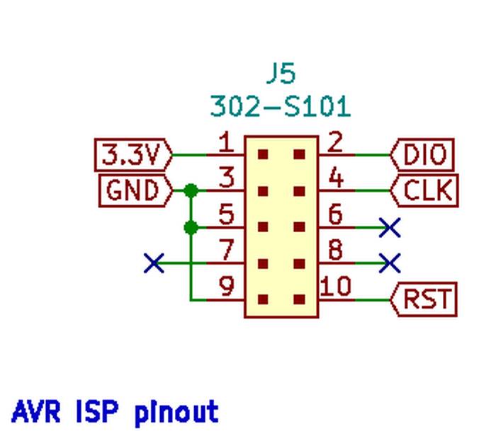
To program this controller it is necessary to load a Bootloader in its first time so that the computer can recognize it. To do this I added a 10 pin AVR ISP ISP since I had an ATMEL-ICE to load the bootloader.
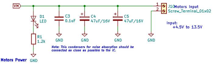
The voltage input for the motors has some capacitors and looks like this
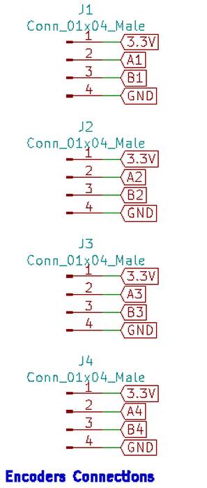
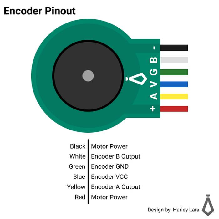
For the encoder connection I am using pin headers that expose 3.3v and GND to power the encoder on the motors and two pins for the motor pulses.
The connection of the drivers for the motors looks like this.
Finally the connections to the microcontroller are as follows.
Due to the amount of connections that are involved this pcb is two-sided and the routing looks like this.
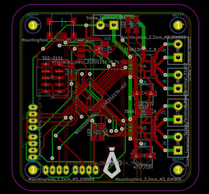
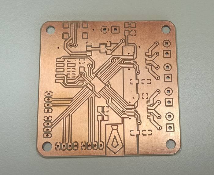
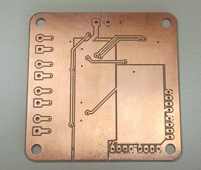
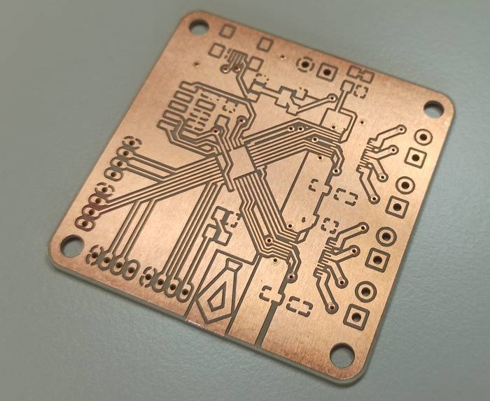
For more information on how to produce a two-sided PCB, visit Fab Motor Controller.
The Arduino Core used to program the SAMD21E17A is thanks to Justin Mattair aka. mattairtech so the definition of pins and their functionalities are described in this link, but at least for me the representation is not very visual so I made my own visual representation based on the table presented by mattairtech.
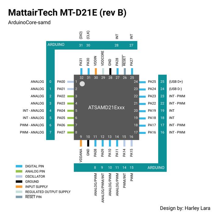
So to program this chip with this Arduino Core you must observe the pin definition for Arduino.
The Firmware programming process starts with the encoders and their interrupts. Because the system has 1 encoder per wheel which makes a total of 4 encoders, and each encoder has two signals A and B that come from two hall sensors and are used to determine the direction of rotation.
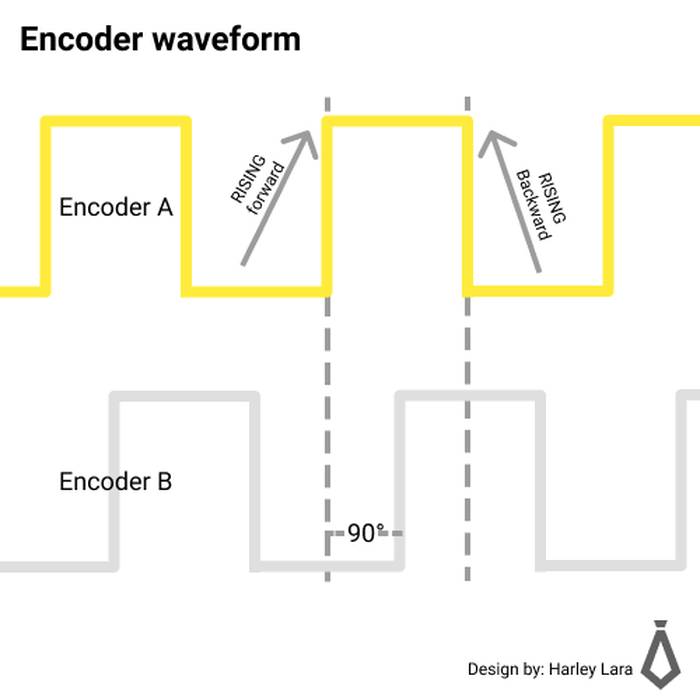
You may think that being 4 encoders with 2 signals each, a total of 8 interrupts are needed (one for each signal), but the truth is that you can use only 4 interrupts taking one of the signals of each encoder as a reference. For example if we take as an interrupt the signal A at the time of RISE we can trigger the interrupt and read the state of encoder B, if encoder B is LOW it means that it goes in one direction and if it is high it goes in the opposite direction. A more visual representation can be found in the following image.
In the Arduino IDE the pins of the encodes are defined as follows
Followed by that you define in the Setup() the interrupts, as mentioned before these interrupts are triggered on a change from low to high.
When an interrupt is triggered it is necessary to define an "Interrupt Service Routine" or better known as ISR, the function is responsible for decreasing or increasing the number of pulses that have been generated in that encoder.

The PID tuning process is complex stuff, and I will give an overview of how the firmware integrates PID control.
Regarding the tunning process to obtain the constants Kp, Ki, Kd there are many methods, some require a lot of mathematics to implement them and others do not require mathematics but requires previous personal experience. In my case it was a manual tunning for two basic reasons, I have previous experience in the tunning process and the system is essentially basic and does not contain dynamic changes that affect the performance of the control.
In the firmware there is a class that contains two methods "setParams" "controlSignal" that are used to define the values of the PID control and the other one to calculate the control signal. Then four instances of the class are created, one for each motor which allows to have different calibration values for each motor, in this case it is not necessary because the system is quite hommogeneous.
class SimplePID{
private:
float Kp, Kd, Ki, umax; // umax maximun PWM value [255]
float prev_error; // Previous error
float integral_error; // Integral error
public:
// Constructor
// Init PID parameter Kp = 1, Ki = 0, Kd = 0
SimplePID() : Kp(1), Ki(0), Kd(0), umax(255), prev_error(0.0), integral_error(0.0){}
// Set parameters
void setParams(float Kp_in, float Ki_in, float Kd_in, float umax_in){
Kp = Kp_in;
Ki = Ki_in;
Kd = Kd_in;
umax = umax_in;
}
// Calculate PID control signal
void controlSignal(int value, int target, float deltaTime, int &pwr, int &dir){
// Calculate error
float error = target - value;
// Derivative
float dedt = (error - prev_error)/deltaTime;
// Integral
float integral_error = integral_error + error * deltaTime;
// Compute control signal
float u = Kp*error + Kd*dedt + Ki*integral_error;
// Motor power
pwr = (int)fabs(u);
if (pwr > umax){
pwr = umax;
}
dir = 1;
if (u < 0){
dir = 0;
}
}
};
/*
* ---- MOTOR DISTRUBUTION ----
* MOTOR 1 = Front Left
* MOTOR 2 = Rear Left
* Motor 3 = Front Right
* Motor 4 = Rear Right
*/
//============================================================================
// PINS DEFINITIONS
//==================================
// MOTOR 3
#define MOTOR3_A 27 //AIN1-2
#define MOTOR3_B 28 //AIN2-2
#define PWM3 8 //PWMA-2
// ENCODER 3
#define ENC3_A 4 // INTERRUPT
#define ENC3_B 0 // DIGITAL PIN
//==================================
//==================================
// MOTOR 4
#define MOTOR4_A 10 //BIN1-2
#define MOTOR4_B 11 //BIN2-2
#define PWM4 15 //PWMB-2
// ENCODER 4
#define ENC4_A 9 // INTERRUPT
#define ENC4_B 2 // DIGITAL PIN
//==================================
//==================================
// MOTOR 1
#define MOTOR1_A 18 //AIN1-1
#define MOTOR1_B 17 //AIN2-1
#define PWM1 16 //PWMA-1
// ENCODER 1
#define ENC1_A 14 // INTERRUPT
#define ENC1_B 3 // DIGITAL PIN
//==================================
//==================================
// MOTOR 2
#define MOTOR2_A 19 //BIN1-1
#define MOTOR2_B 22 //BIN2-1
#define PWM2 23 //PWMB-1
// ENCODER 2
#define ENC2_A 5 // INTERRUPT
#define ENC2_B 1 // DIGITAL PIN
//==================================
//==================================
#define STBY_1 6 // Stanby driver 1 (HIGH to enable the driver)
#define STBY_2 7 // Stanbt driver 2 (HIGH to enable the driver)
//==================================
//============================================================================
//============================================================================
// Motors array
#define NMOTORS 4 // Numbers of motors
// Control pinss A array - Motors
const int motors_a[] = {MOTOR1_A, MOTOR2_A, MOTOR3_A, MOTOR4_A};
// Control pinss B array - Motors
const int motors_b[] = {MOTOR1_B, MOTOR2_B, MOTOR3_B, MOTOR4_B};
// PWM PINs
const int pwm[] = {PWM1, PWM2, PWM3, PWM4};
//============================================================================
// Create Class instance
SimplePID pid[NMOTORS];
//============================================================================
// ENCCODERs
// Encoders PINs array
const int enc_a[] = {ENC1_A, ENC2_A, ENC3_A, ENC4_A};
const int enc_b[] = {ENC1_B, ENC2_B, ENC3_B, ENC4_B};
// Encoders position array
volatile int enc_pose[] = {0, 0, 0, 0}; // Init on zero
//============================================================================
//============================================================================
// RPM
#define PULSES 12
// The encoder registers 48 pulses in total
// for both sensors, high and low per rotation.
// But because only the high pulse of one of the sensors is recorded,
// the number of pulses recorded per rotation is 12
#define WHEEL_CIRCUMFERENCE 2.0404// unit in meters
#define GEAR_RATIO 107.5 // Gearbox: 107.5:1;
float total_pulses = PULSES * GEAR_RATIO; // Pulses per turn
float pulsesPerMeter = total_pulses * WHEEL_CIRCUMFERENCE;
//============================================================================
// Every 1000ms
#define SAMPLE_TIME 1000
long previousMillis = 0;
long currentMillis = 0;
//==================================
long currentTime = 0;
long previousTime = 0;
float previousError = 0;
float integralError = 0;
float deltaTime = 0;
int error = 0;
float target_f[] = {0.0, 0.0, 0.0, 0.0};
long target[] = {0, 0, 0, 0};
// TODO
// fix rotation per seconds
// implement Serial comunication
float velocity[4] = {0.0, 0.0, 0.0, 0.0};
int velocity_int[4] = {0, 0, 0, 0};
void setTarget(float t, float deltat){
float positionChange[4] = {0.0, 0.0, 0.0, 0.0};
//t = fmod(t, 0.001); //time in seconds
//Serial.print("[DEBUG] Velocity: ");
//Serial.println(velocity[0]);
for (int k = 0; k < 4; k++){
positionChange[k] = velocity[k] * deltat * pulsesPerMeter;
}
// else if (t < 8){
// // BACKWARD
// velocity[0] = -0.8;
// velocity[1] = -0.8;
// velocity[2] = -0.8;
// velocity[3] = -0.8;
// for (int k = 0; k < 4; k++){
// positionChange[k] = velocity[k] * deltat * pulsesPerMeter;
// }
// }
// else if (t < 12){
// // LEFT
// velocity[0] = -0.8;
// velocity[1] = 0.8;
// velocity[2] = -0.8;
// velocity[3] = 0.8;
// for (int k = 0; k < 4; k++){
// positionChange[k] = velocity[k] * deltat * pulsesPerMeter;
// }
// }
// else if (t < 16){
// // RIGHT
// velocity[0] = 0.8;
// velocity[1] = -0.8;
// velocity[2] = 0.8;
// velocity[3] = -0.8;
// for (int k = 0; k < 4; k++){
// positionChange[k] = velocity[k] * deltat * pulsesPerMeter;
// }
// }
//Serial.print("[DEBUG] PositionChange: ");
//Serial.println(positionChange[0]);
for (int k = 0; k < 4; k++){
target[k] = (target[k] + positionChange[k]);
}
//Serial.println(positionChange[0]);
// for (int k = 0; k < 4; k++){
// enc_pose[k] = 0;
// }
}
void setup() {
Serial.begin(9600);
for (int k = 0; k < NMOTORS; k++){
// motors pin mode
pinMode(motors_a[k], OUTPUT);
pinMode(motors_b[k], OUTPUT);
pinMode(pwm[k], OUTPUT);
// Encoders pin mode
pinMode(enc_a[k], INPUT);
pinMode(enc_b[k], INPUT);
pid[k].setParams(1, 0, 0, 255);
}
// Interrupts definitions
attachInterrupt(digitalPinToInterrupt(ENC1_A), triggerEncoder<0>, RISING);
attachInterrupt(digitalPinToInterrupt(ENC2_A), triggerEncoder<1>, RISING);
attachInterrupt(digitalPinToInterrupt(ENC3_A), triggerEncoder<2>, RISING);
attachInterrupt(digitalPinToInterrupt(ENC4_A), triggerEncoder<3>, RISING);
//==================================
// ---- STANDBY ----
pinMode(STBY_1, OUTPUT);
pinMode(STBY_2, OUTPUT);
digitalWrite(STBY_1, HIGH); // HIGH to enable the driver
digitalWrite(STBY_2, HIGH); // HIGH to enable the driver
//==================================
delay(5000);
}
long prevT = 0;
void loop() {
while (Serial.available() > 0){
velocity_int[0] = Serial.parseInt();
velocity_int[1] = Serial.parseInt();
velocity_int[2] = Serial.parseInt();
velocity_int[3] = Serial.parseInt();
velocity[0] = (float)velocity_int[0]/100;
velocity[1] = (float)velocity_int[1]/100;
velocity[2] = (float)velocity_int[2]/100;
velocity[3] = (float)velocity_int[3]/100;
// Serial.print(velocity[0]);
// Serial.print("|");
// Serial.print(velocity[1]);
// Serial.print("|");
// Serial.print(velocity[2]);
// Serial.print("|");
// Serial.println(velocity[3]);
}
// get Current time
long currT = micros();
float deltaT = ((float) (currT - prevT))/(1.0e6);
prevT = currT;
setTarget(currT/1.0e6, deltaT); // in milli
int pos[NMOTORS];
noInterrupts();
for(int k = 0; k < NMOTORS; k++){
pos[k] = enc_pose[k];
}
interrupts();
for (int k = 0; k < NMOTORS; k++){
int pwr, dir;
pid[k].controlSignal(pos[k], target[k], deltaT, pwr, dir);
runMotor(motors_a[k], motors_b[k], pwm[k], pwr, dir);
}
// For debbuging
for (int k = 0; k < NMOTORS; k++){
Serial.print(target[k]);
Serial.print(" ");
Serial.print(pos[k]);
Serial.print(" ");
}
Serial.println();
}
void runMotor(int input_1, int input_2, int pin_pwm, int input_speed, bool dir){
/*
* runMotor(PIN_1, PIM_2, PIN_PWM, PIN_PWM[0 to 255], dir[0 (BACKWARD) or 1 (FORWARD)])
*/
analogWrite(pin_pwm, input_speed);
if (dir == true){
digitalWrite(input_1, HIGH);
digitalWrite(input_2, LOW);
}
else{
digitalWrite(input_1, LOW);
digitalWrite(input_2, HIGH);
}
}
template
void triggerEncoder(){
if (digitalRead(enc_b[j]) == LOW){ // Forward
enc_pose[j] ++;
}else{ // Backward
enc_pose[j] --;
}
// for debugging
// Serial.print("ENCODER ");
// Serial.print(j+1);
// Serial.println(" triggered");
}