Electronics Production
Assignment Requirements:
- Characterize the design rules for your PCB production process: document feeds, speeds, plunge rate, depth of cut (traces and outline) and tooling.
- Document your work (in a group or individually)
- Make an in-circuit programmer by milling and stuffing the PCB, test it, then optionally try other PCB fabrication process.
Learning Outcomes:
Introduction:
For the group assignment, we fabricated the resolution test (traces & outline) on 3 CNC milling machines. First on Roland Modela MDX-20, Second on a chinese CNC milling machine and third on MonoFab SRM-20. Each macine has its resolution results.
For the individual assignment I decided to make Ali's FabOptimus ISP, I chose the Design Files (R_pullup=1K+0.5K).
Steps in General:
- Step(1): Fabricating the resoultion test on a Chinese CNC milling machine
- Step(2): Fabricating Ali's FabOptimus ISP on MonoFab SRM-20
- Step(3): Stuffing and soldering the PCB
- Step(4): Programing and testing
Steps in Details:
Step(1): Fabricating the resoultion test on a Chinese CNC milling machine
- I downloaded the traces and outline images as .png files.
- I opened Fabmodules.org on Chrome, From the input format I selected image (.png), From output format I selected G-code (.nc) and then chose PCB traces (1/64)
- I set the cut speed to 2 mm/s instead of 4 mm/s, made the plunge speed to 1 mm/s and the jog height to 2 mm
- Cut depth was set to 0.1 mm and the used tool was a v-carve 0.4 mm and made the no. of offsets 4.
- Clicked on Calculate then Save, the output files will be traces.nc
- I will be using a chinese CNC milling machine, its area is 30 cm * 40 cm and we, at Fab Lab Egypt, changes its control board to OpenBuilds controller.
- I used an FR1 single layer PCB sheet with dimensions of 15 cm * 15 cm.
- I used a yellow paint tape on the other side of the board and then used a double sided tape in order to fix the board on the sacrificial bed properlly.
- I used the 0.4 mm end mill for the traces. I have to be carefull while using this end mill as it can break easily.
- The machine will run milling the traces, it removes copper at each track side.
- After finishing the traces, I used a 1.5 mm end mill to cut the outline.
- I noticed that the machine requires calibration in X and Y axes, as the trace width is smaller than its designed width. So, I will calibrate the machine and run the file again to have better results.


Step(2): Fabricating Ali's FabOptimus ISP on MonoFab SRM-20
- I downloaded Ali's FabOptimus ISP (traces & outline). I chose Design Files (R_pullup=1K+0.5K)
- I used fabmodules to import the traces.png image and selected the output format to G-code (.nc) and selected 1/64 inch end mill to the tracing.
- I set the cut speed to 4 mm/s, plunge speed to 1mm/s, jog height to 1.5 mm
- Aslo set the cut depth to 0.1 mm (it is the copper layer thickness) and 4 offsets.
- I saved the file (traces.nc)
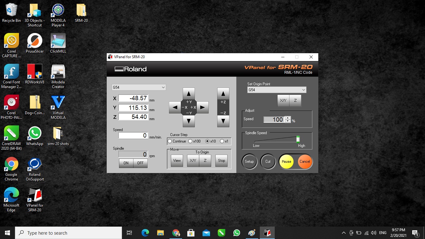
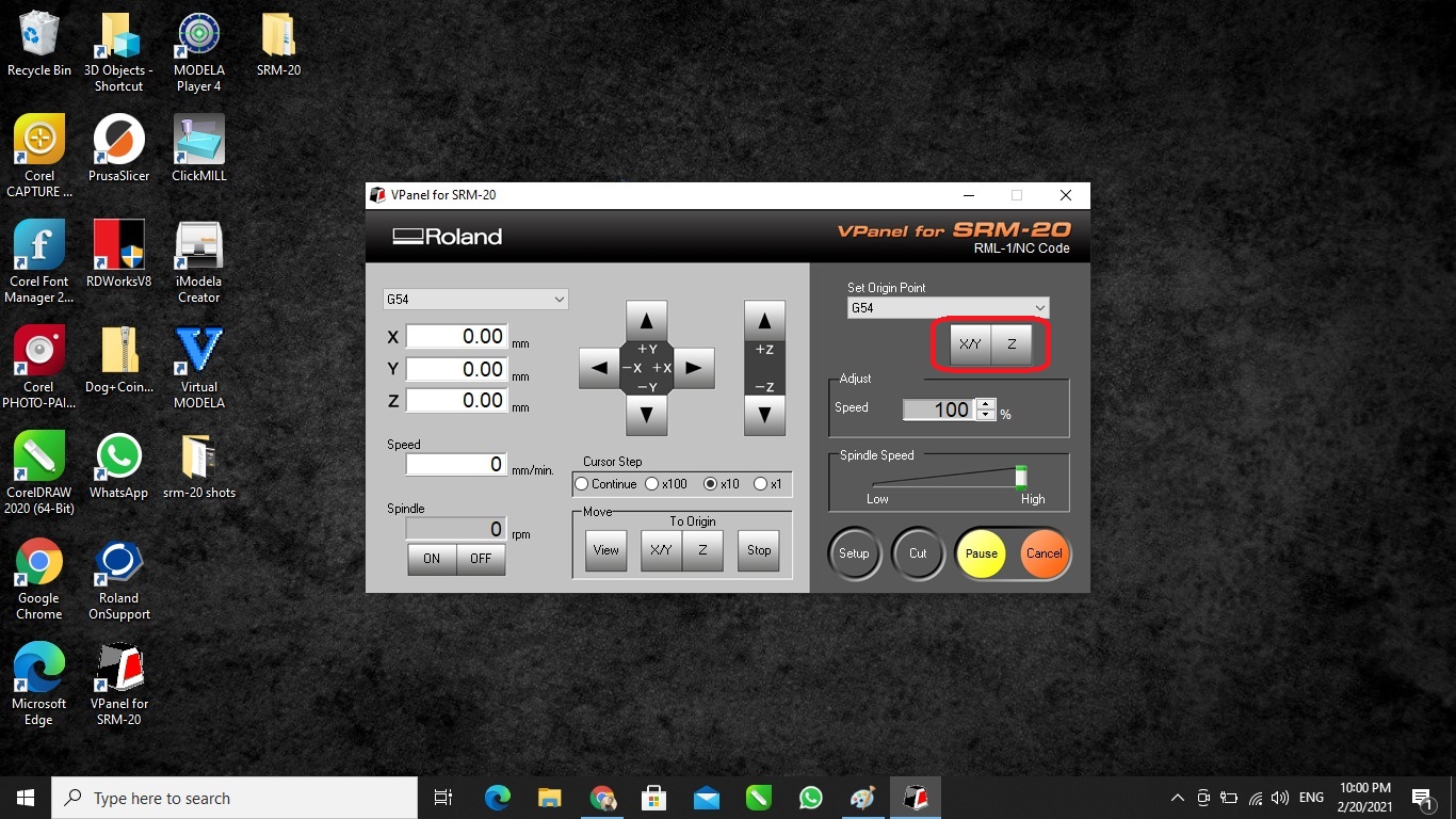
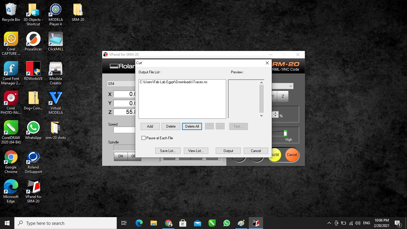
- Opened V-Panel to set the origin of the tool and to load the traces file.
- I used paint tape and double face to fix the board to the bed.
- Then I used the 0.4 mm v-bit to run the trace milling, I used a hex allen to fix the tool into the spindle collet.
- I set the origin to the front left corner and run the traces file
- I imported the outline image to Fabmodules, selected G-code as output format, chose PCB outline(1/32).
- I set the cut speed to 2 mm/s, plunge speed to 2 mm/s and job height to 1.5 mm.
- I set the cut depth (per path) to 0.6 mm to cut the whole thickness of 1.7 mm.
- Then imported the .nc file into the V-Panel.
- I used a 1.5 mm end mill to cut the outline, fixed it on the spindle collet using the allen key
- Finally I removed the PCB from the board and it looked very fine!


Step(3): Stuffing and soldering the PCB
- This is the components' list and their quantities to be prepared before soldering:
- I started soldering the ATTINY44A then the components from center to outside
- It was useful to use a SMD resistor code calculator to make sure I am using the correct ones.
- Tools used while soldering: soldering iron, soldering stand, soldering wire, solder sucker, tweezer and wet sponge.
| Component | Description | QTY |
|---|---|---|
| ATTINY44A-SSU-ND | IC AVR MCU 4K 10MHZ 8SOIC- | 1 |
| H2961CT-ND | CONN RECEPT MINI USB2.0 5POS | 1 |
| 609-5161-1-ND | 6 Positions Header Connector 0.100" SMD | 1 |
| 311-10.0KFRCT-ND | RES 10.0K OHM 1-4W 1% 1206 SMD | 1 |
| 311-1.00KFRCT-ND | RES 1.00K OHM 1-4W 1% 1206 SMD | 1 |
| 311-100FRCT-ND | RES 100 OHM 1-4W 1% 1206 SMD | 2 |
| 311-499FRCT-ND | RES 499 OHM 1-4W 1% 1206 SMD | 1 |
| 311-0.0ERCT-ND | RES 0.0 OHM 1-4W 1% 1206 SMD | 1 |
| XC1109CT-ND | CER RESONATOR 20.00MHZ SMD | 1 |
| 445-1423-1-ND | CAP CER 1UF 50V X7R 10% 1206- | 1 |
| BZT52C3V3-FDICT-ND | DIODE ZENER 500MW 3.3V SOD123 | 2 |


Step(4): Programming and testing
- I used the ATMEL AVR USBasp Programmer and the AVR ISP 10Pin To 6Pin Converter to connect the board to the PC/Laptop and then program it.
- I downloaded the firmware.zip and the windows drivers.zip of the programmer, then I installed the driver.
- I also downloaded the AVRDUDESS and installed it.
- In the AVRDUDESS, I pressed on Detect and then flashed the main.hex file from the firmware.zip and used the shown Fuses & lock bits.
- I connected the board to my laptop and now it is defined and well connected.


Finally, I have:
√ Characterized the design rules for our PCB production process: documented feeds, speeds, plunge rate, depth of cut (traces and outline) and tooling.
√ Made an in-circuit programmer by milling and stuffing the PCB and finally tested it.