Final project
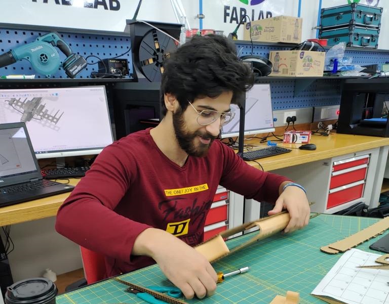
In this page you will find all the manufacturing processes that I used to make the final project which is a light weight RC airplane that is made using only digital fabrication processes.
Learning outcomes
- Create your own integrated design
- Demonstrate 2D & 3D modelling capabilities applied to your own designs.
- Select and apply appropriate additive and subtractive techniques
- Demonstrate competence in design, fabrication and programming of your own fabbed microcontroller PCB, including an input & output device
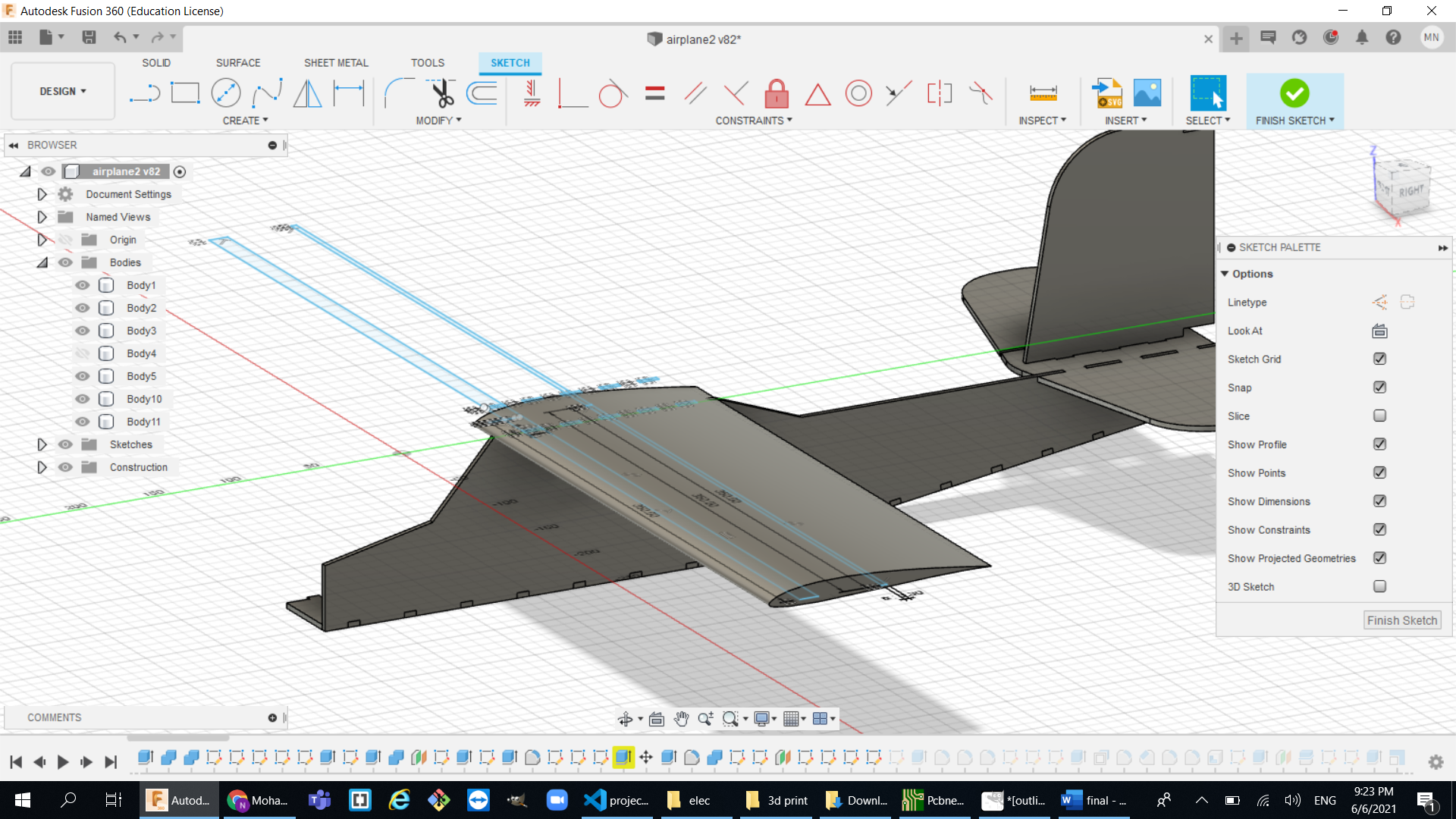
The design
The design was a really big factor in making this airplane and it really did take a lot of time to establish the following design:
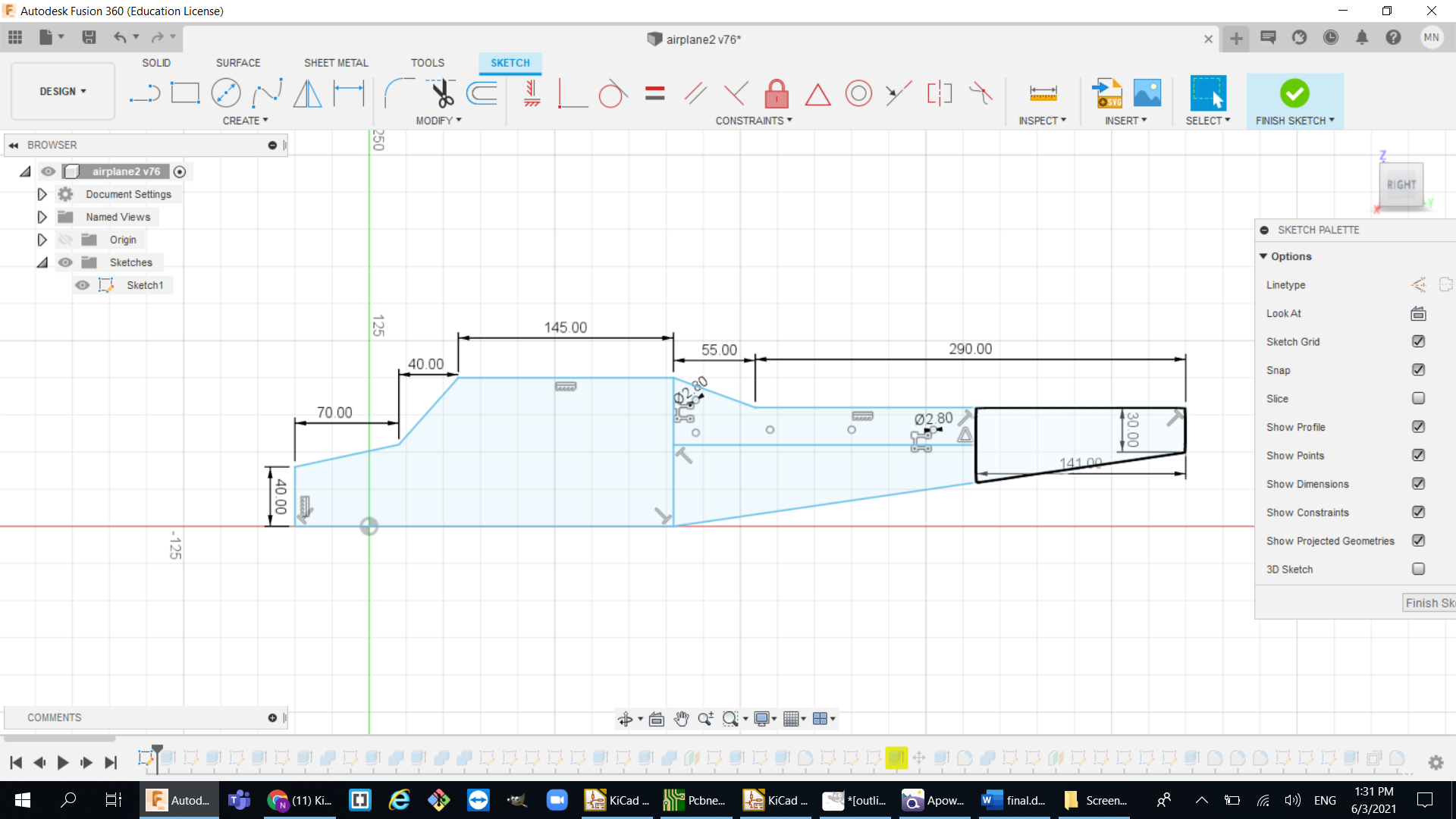
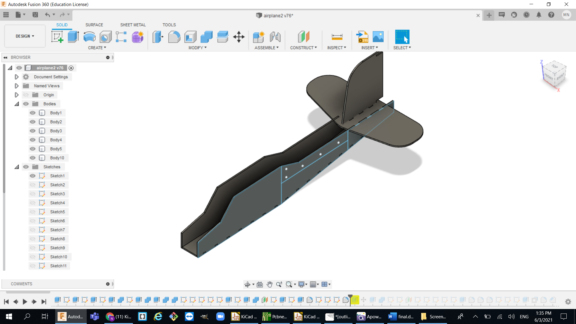
The main frame:
- Since I will be using the laser cutter to make the mainframe and thankfully our machine is big enough to cut up to 800mm wide, so my main frame width was 600mm:
- I used a finger joint system to connect between the frame parts to create this airplane shape and it is ready to cut out my first test for the main frame:
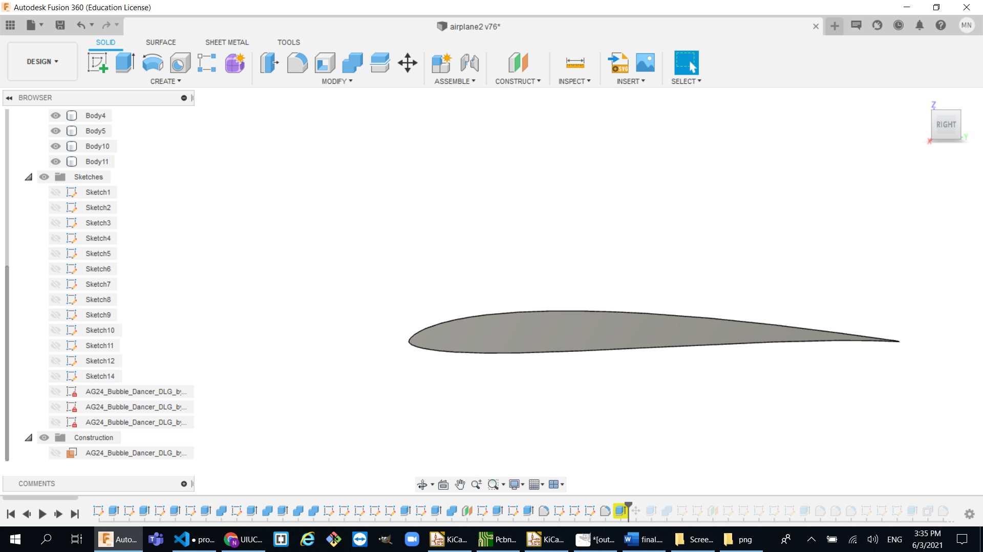
- After that I wanted to get a shape of an actual airfoil so my airplane can have a good aerodynamic system so I used the UIUC airfoils data base to get an actual airfoil shape then I adjusted to fit my airplane size:
-
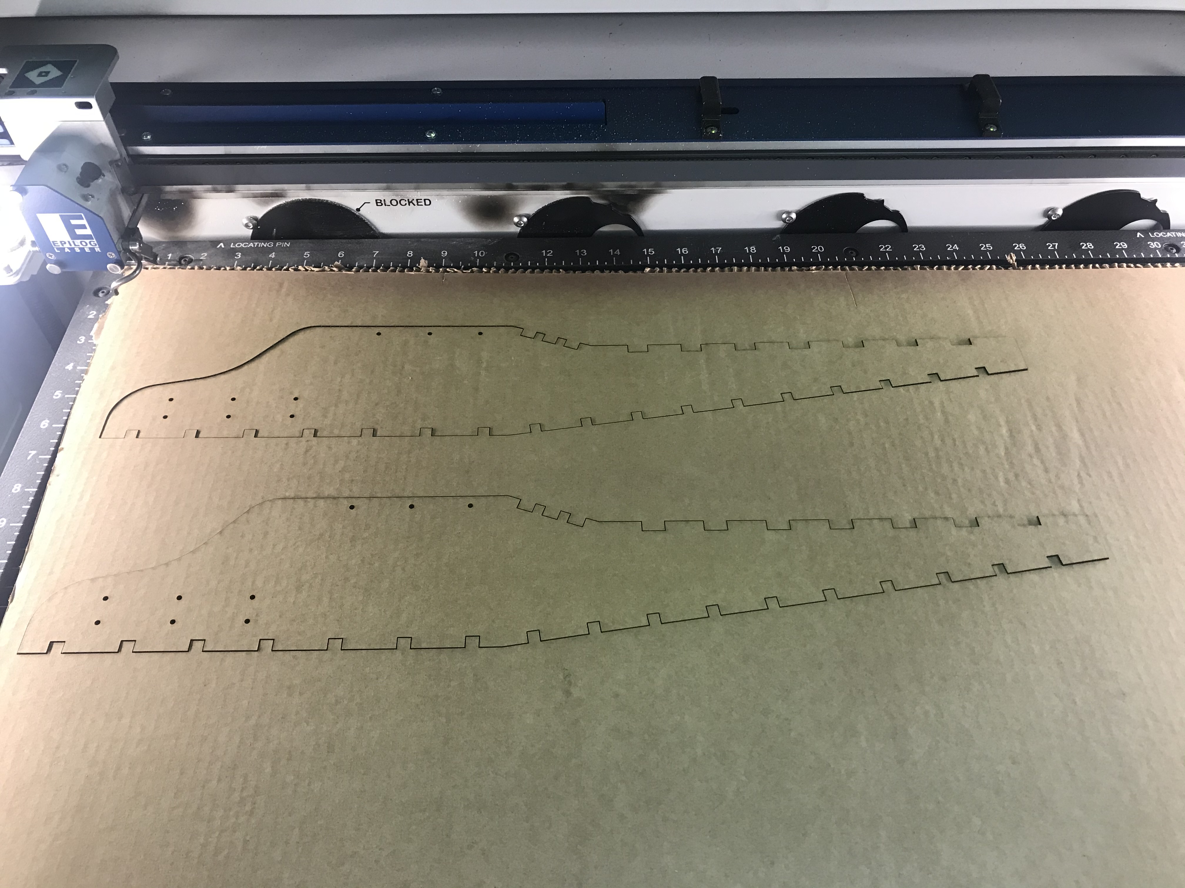
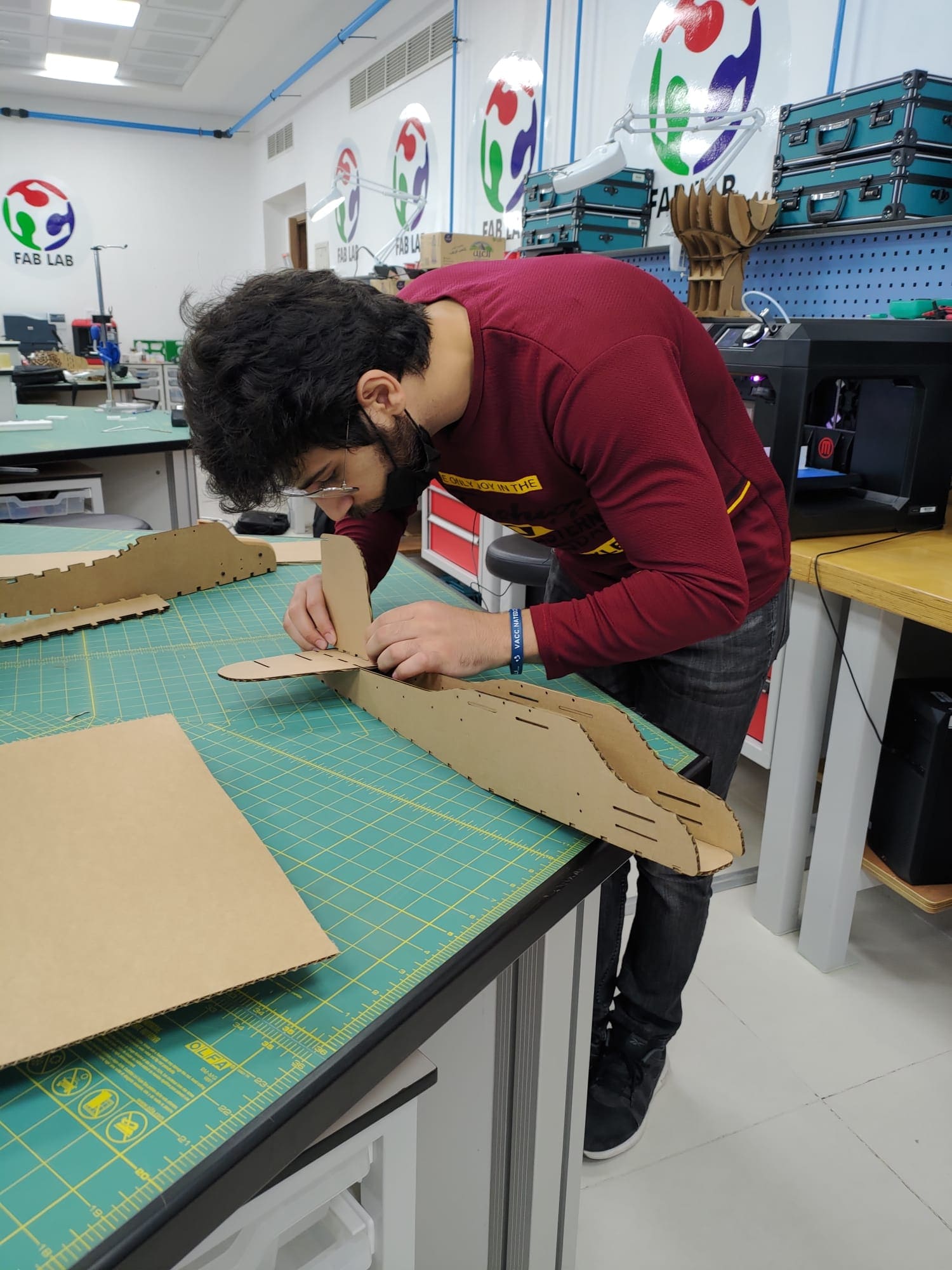
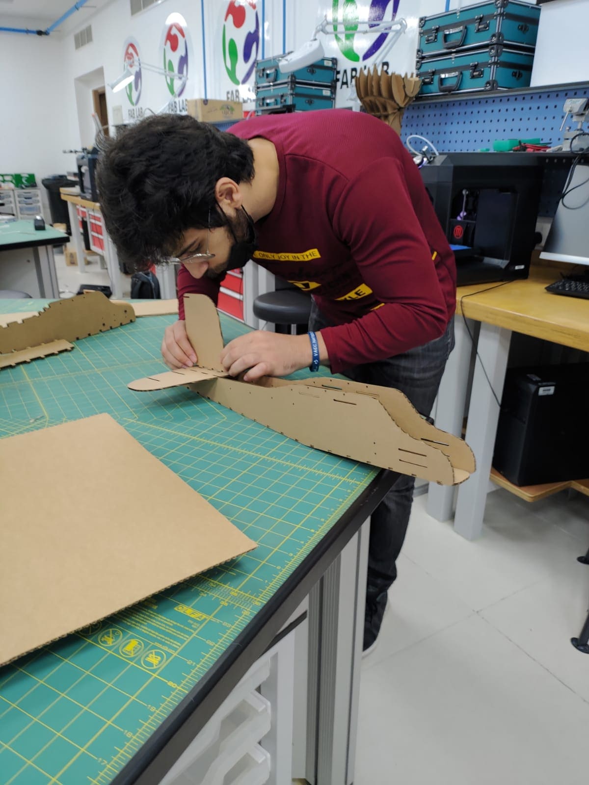
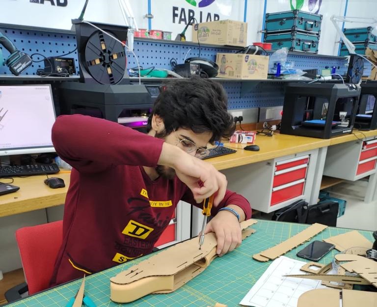
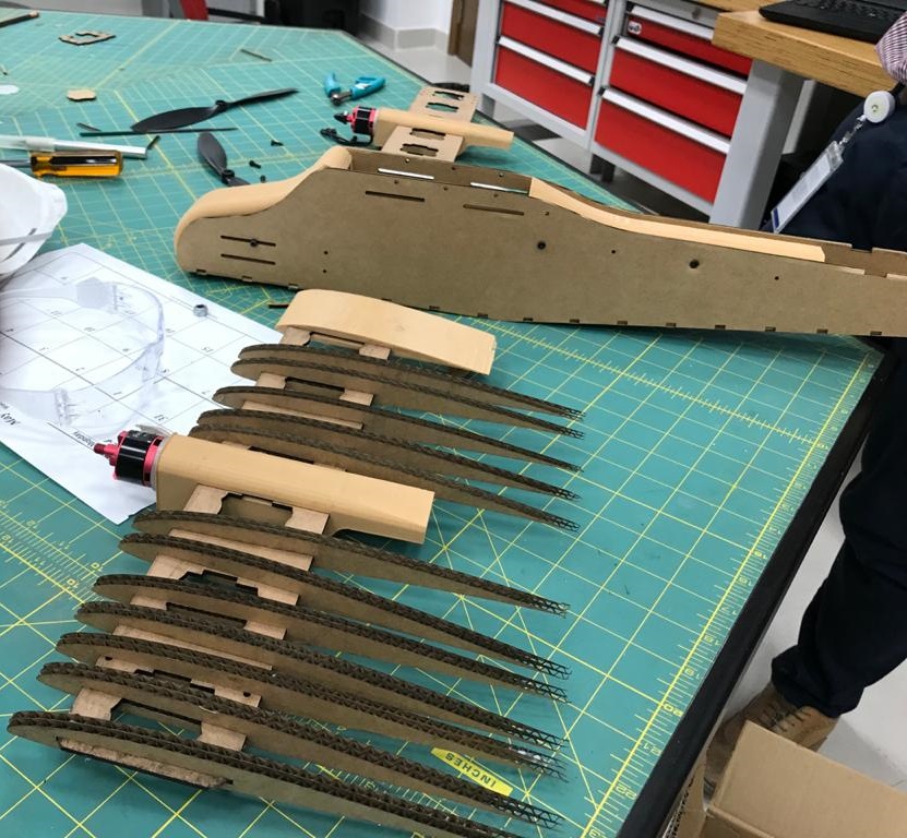
First test of the frame:

- After figuring out how to fix the laser cutter probelm I maanaged to cut it the full body with no errors and I also used half sheet cardboard:
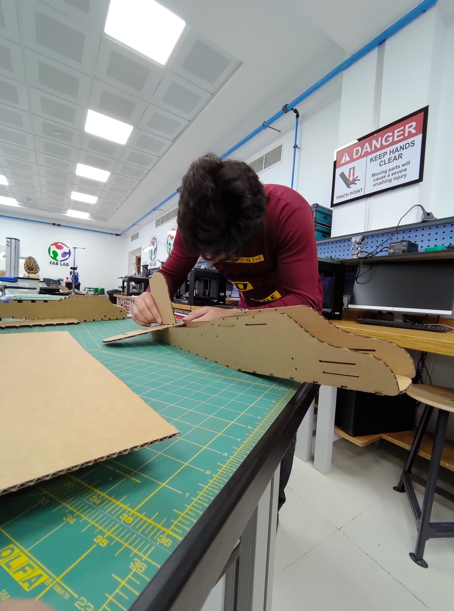
- some pictures of assembling the frame:
Note: After cutting the frame I noticed that the laser cutter isnt actually printing all the way through so this was the first problem I faced with this design and also the weight was kind of heavey so I decided to go for half sheet cardboard as it is way lighter.

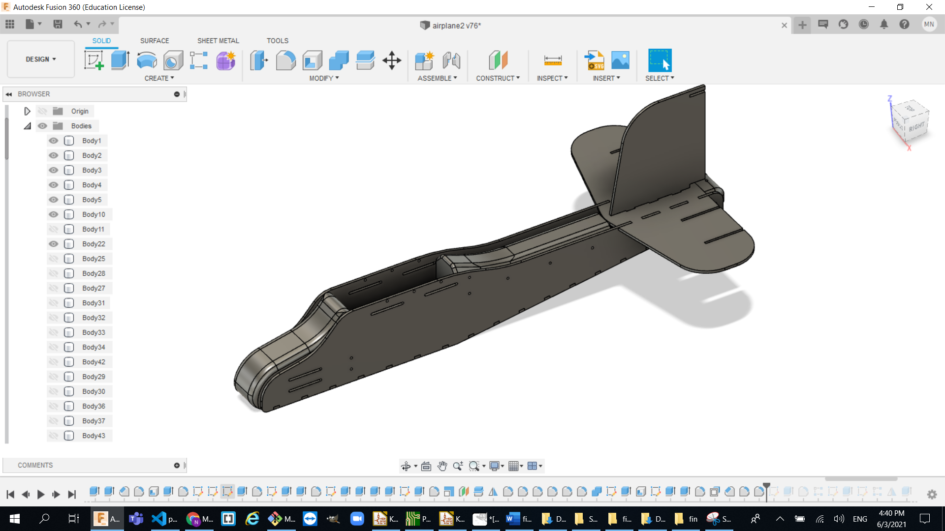
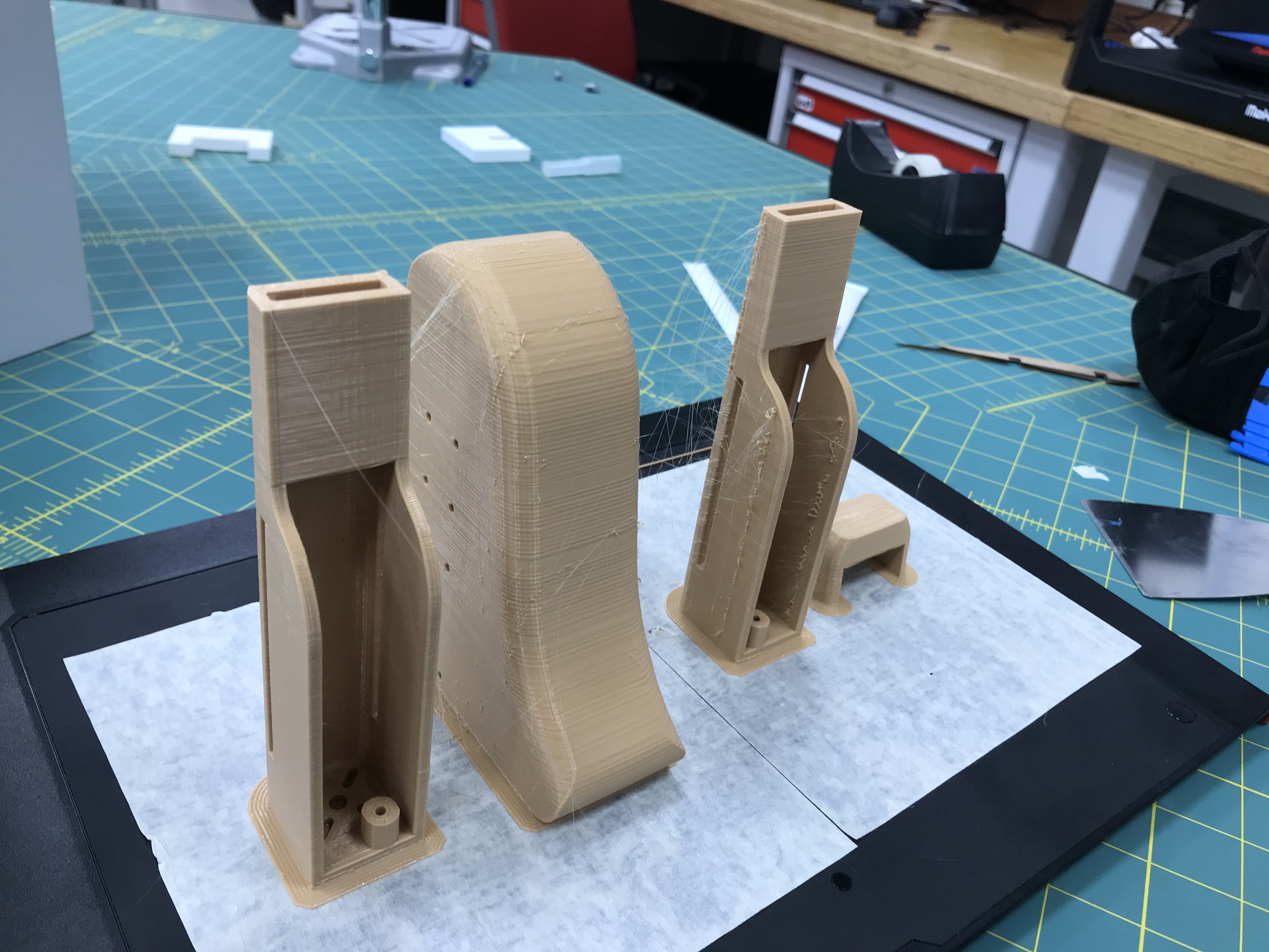
The upper side:
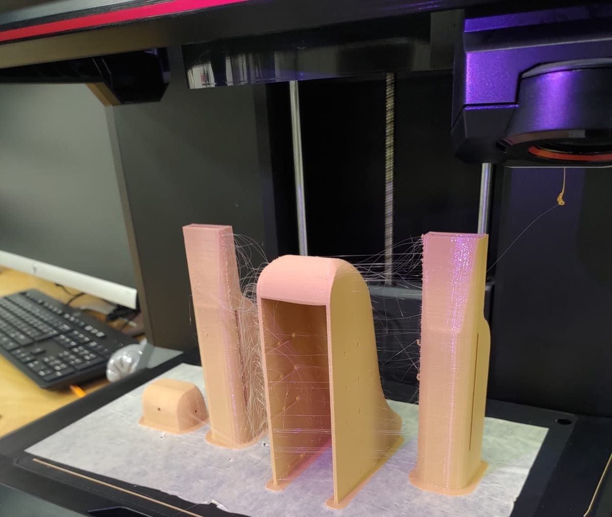
So, I wanted to make the airplane look cool, so I decided to use 3d printed designs to close up the upper part of the airplane. There are three 3d printable parts:
- The head:
- The body:
- The tail:


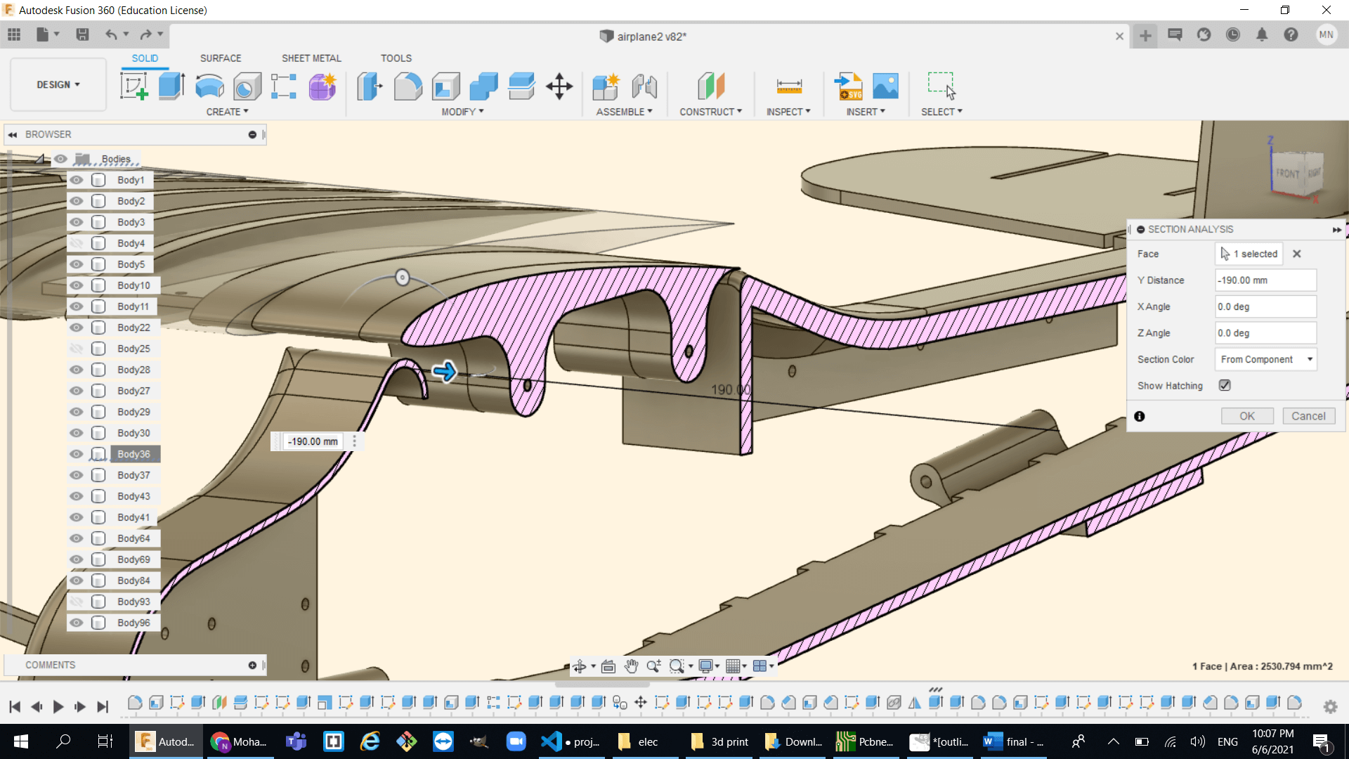
This is how the model looks like after adding these part and filleting some edges:
Printing and assembling the parts:
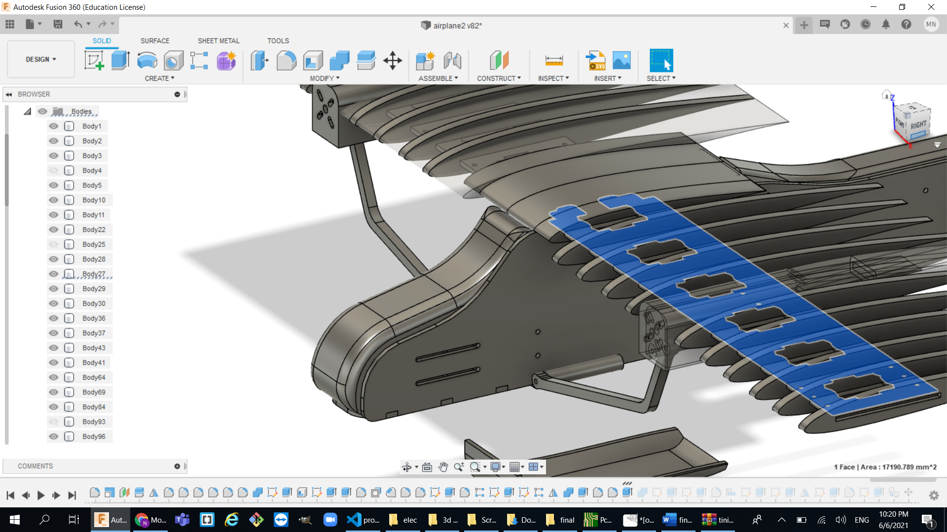
The airfoil:
Designing an airfoil was a bit tricky because as you can already tell it can not be printed as one unit and the magically stick it to the airplane so here some the ideas we had and tried:
- First airfoil test :
- the airfoil shape was way too small and fragile because it was made from cardboard so I did some adjustment in the design by scaling it up a little so it can have more rigidity.
- The two sticks were not enough to connect between the airfoil segments so I did another design that can have a better connection system.
- Second airfoil test :
- the connection system was changed to the following:
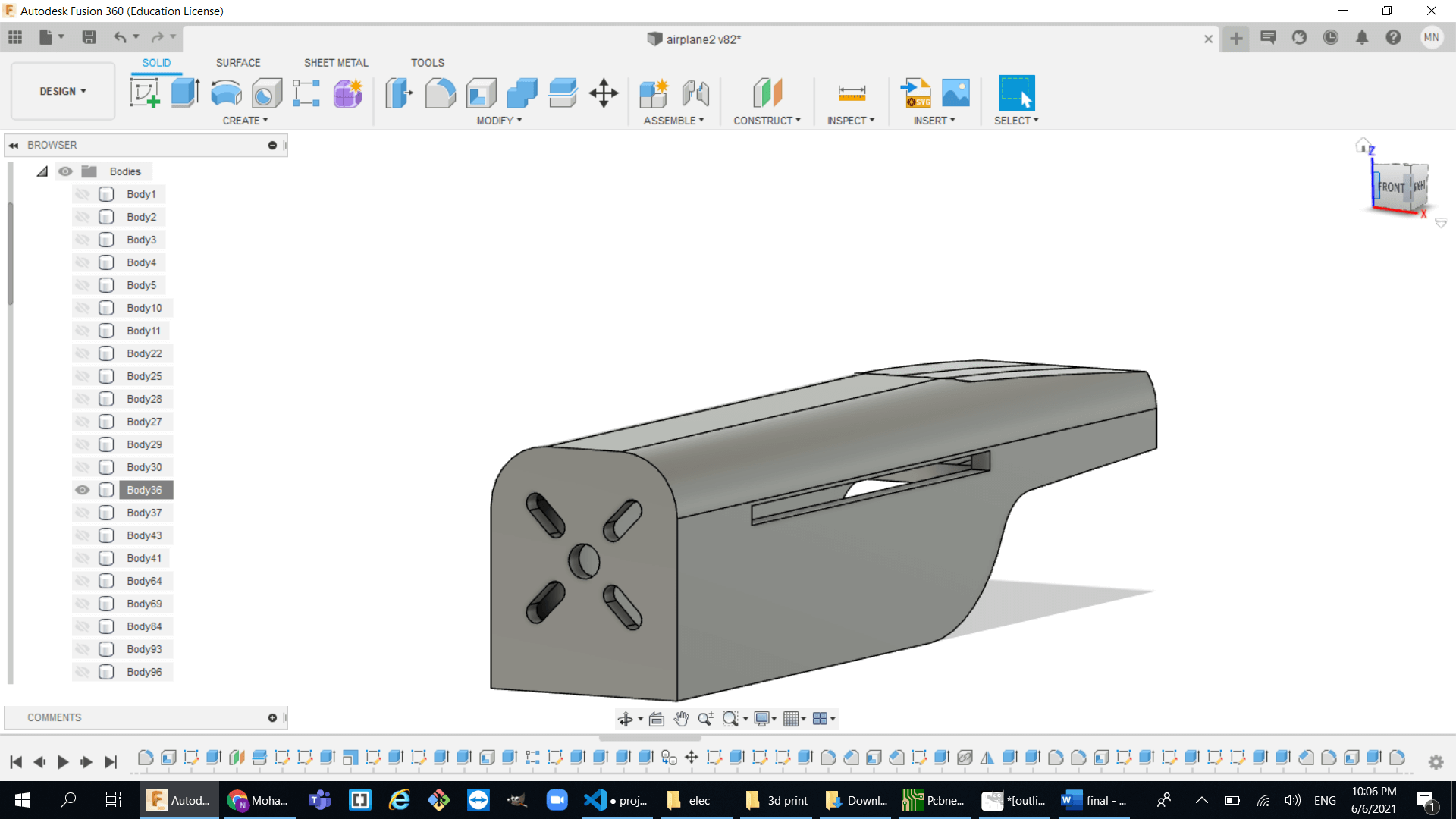
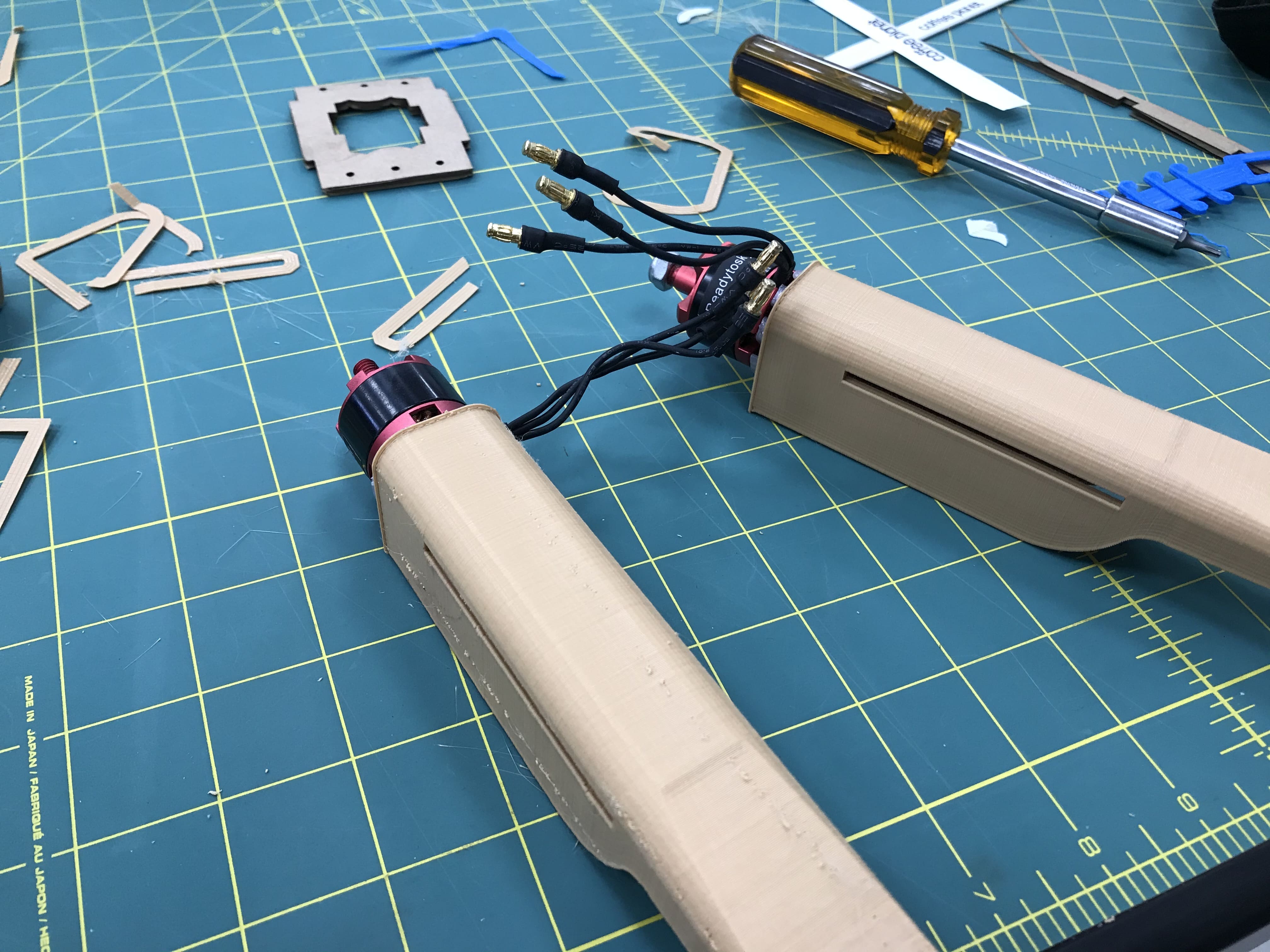
- the motor mount design:
- the connectors between the wing and the main frame:
The first test was to make like two long sticks that connects between laser cut airfoil shaped cardboard and then it can form a wing.I noticed two problems with this design:
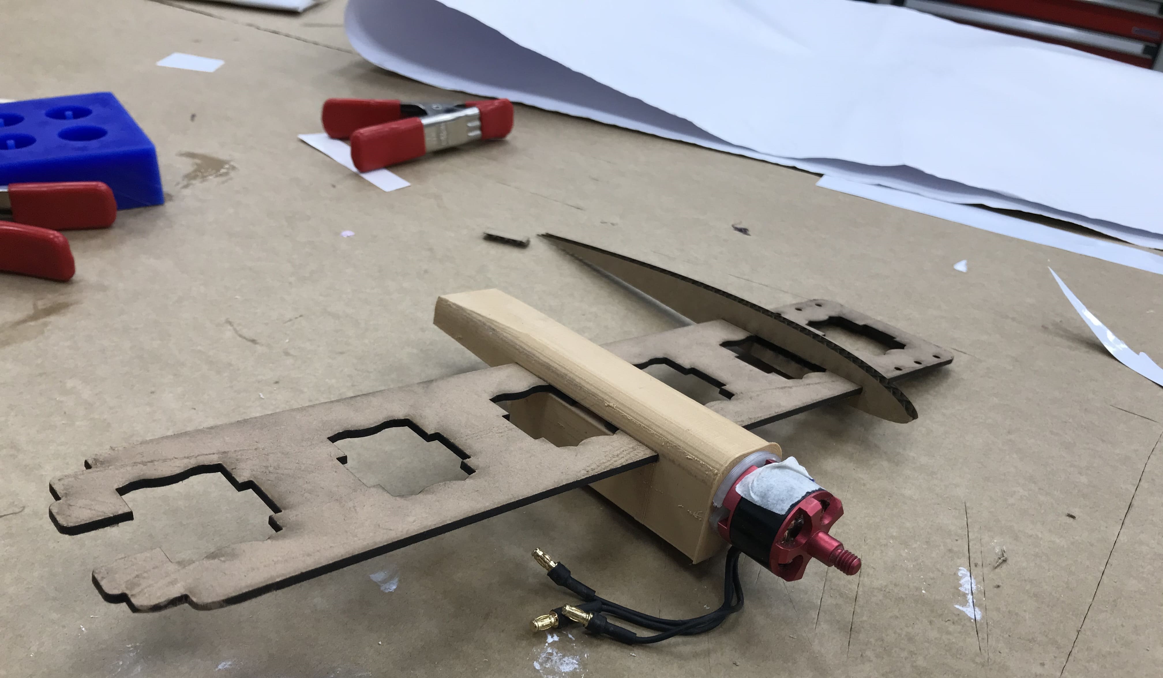
Ok so I know that the airfoil shape cant be just cardboard since it is way too weak to handle the overhanging weight so I decided to 3d print some parts of the wing like the motor mount since it has the most weight and the another one that connects between the wing with the main frame so there are the changes I did :
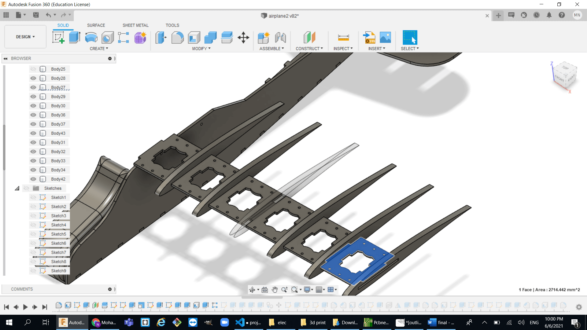
most of the problems was solved with this design but still it was not rigid enough to handle the load of the motor.Since cardboard was too weak to connect between the airfoil segments I decided to use different material and I chose wood because it was available in the lab and it doesnt have that much weight so I just joined all the little connectors to form one long connector.
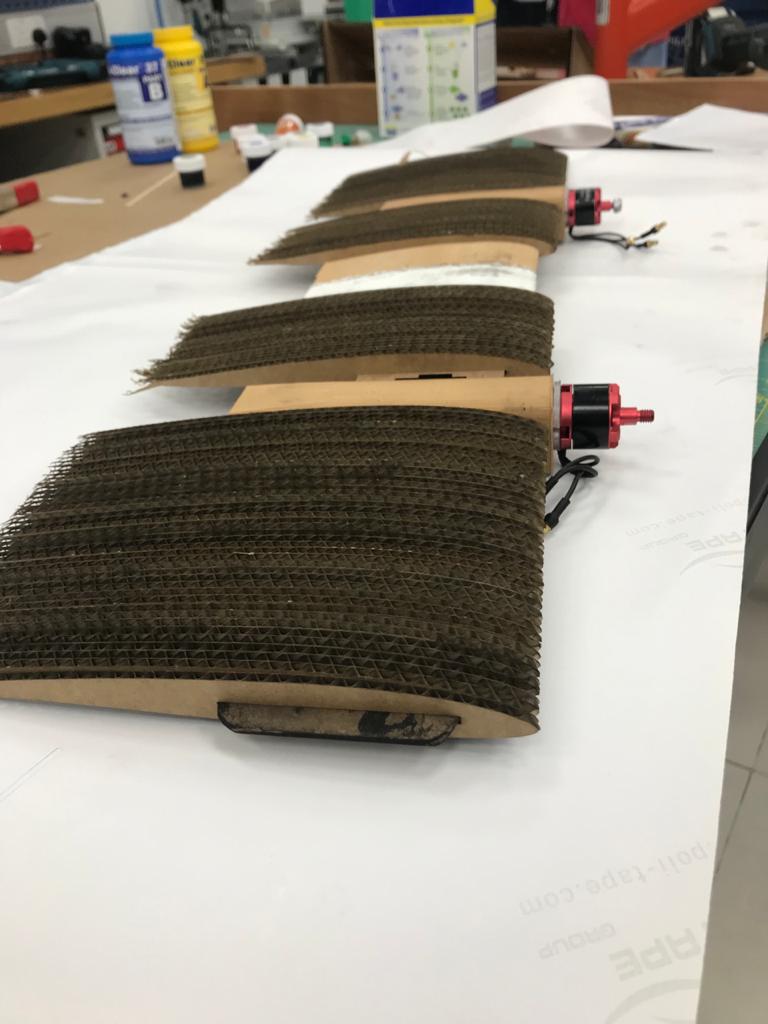
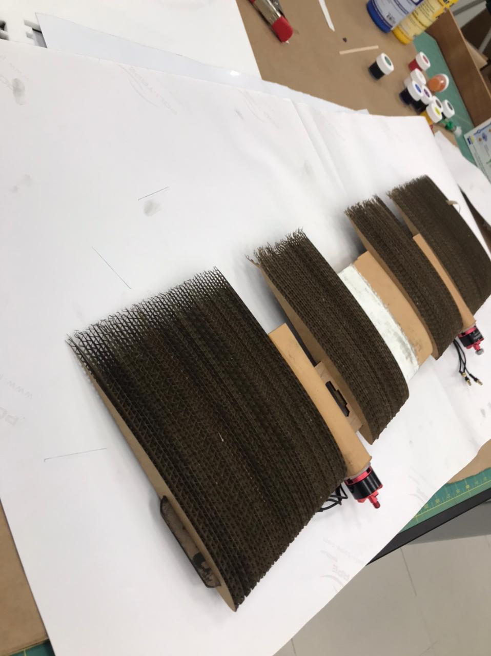
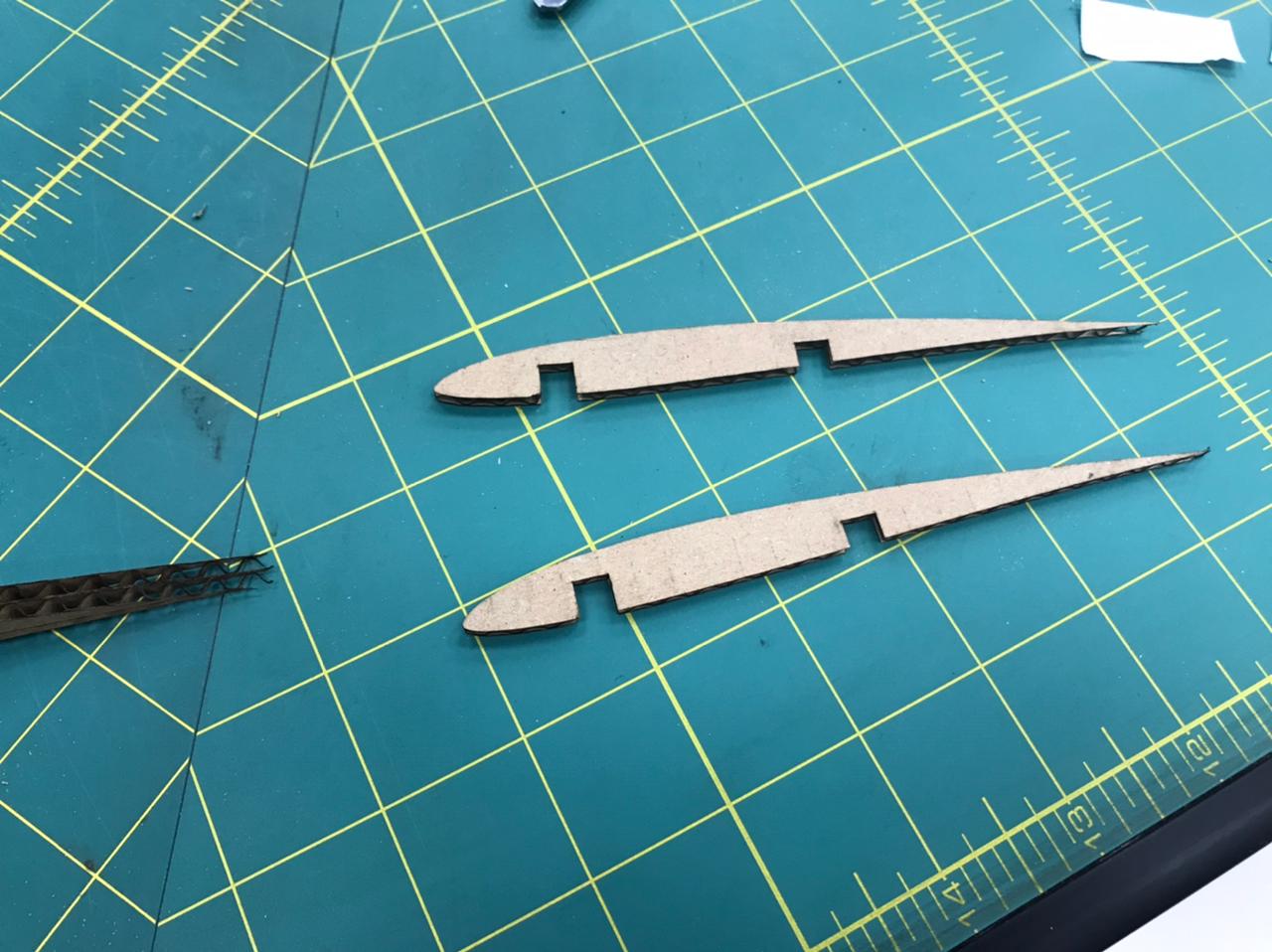
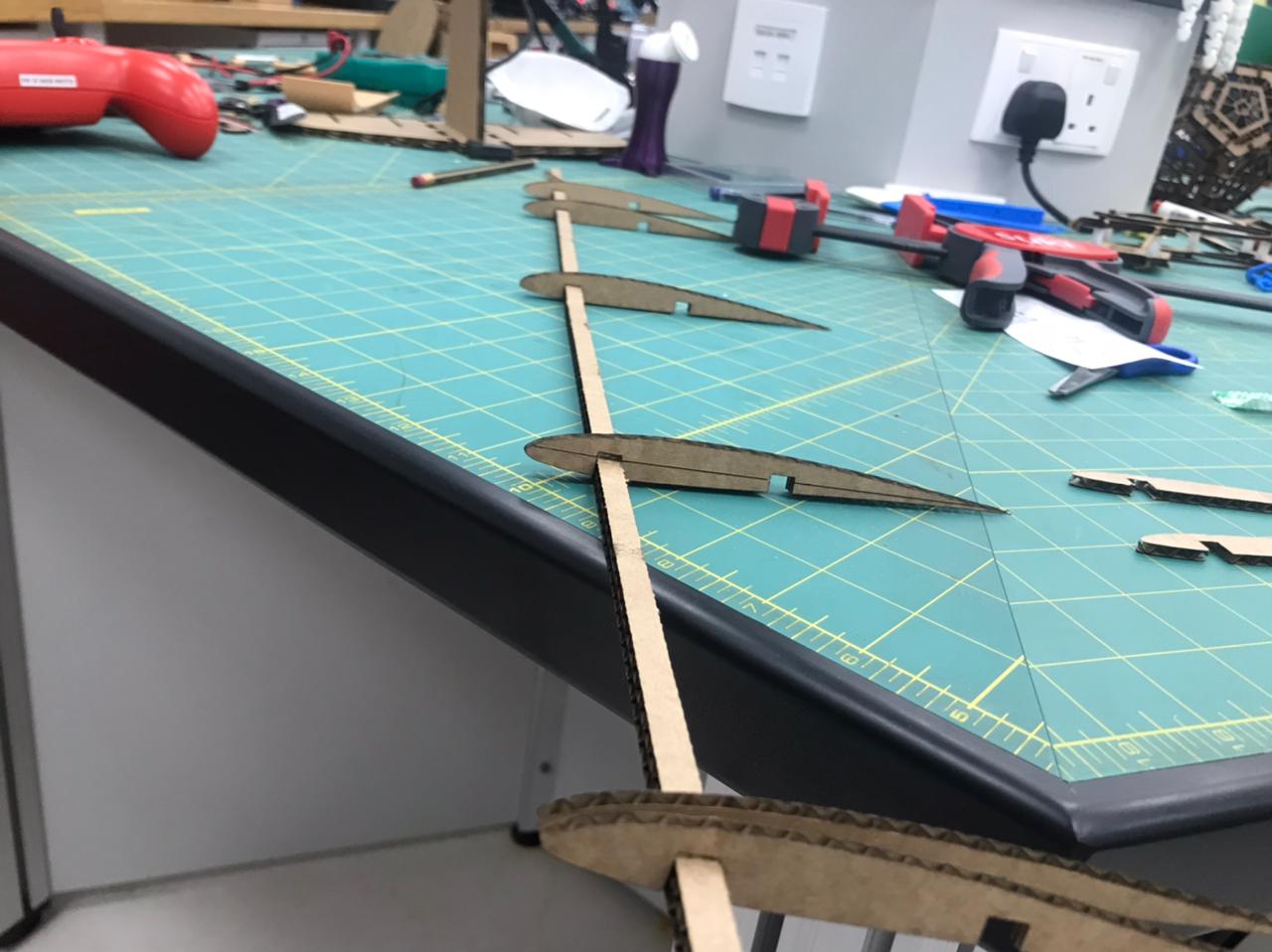
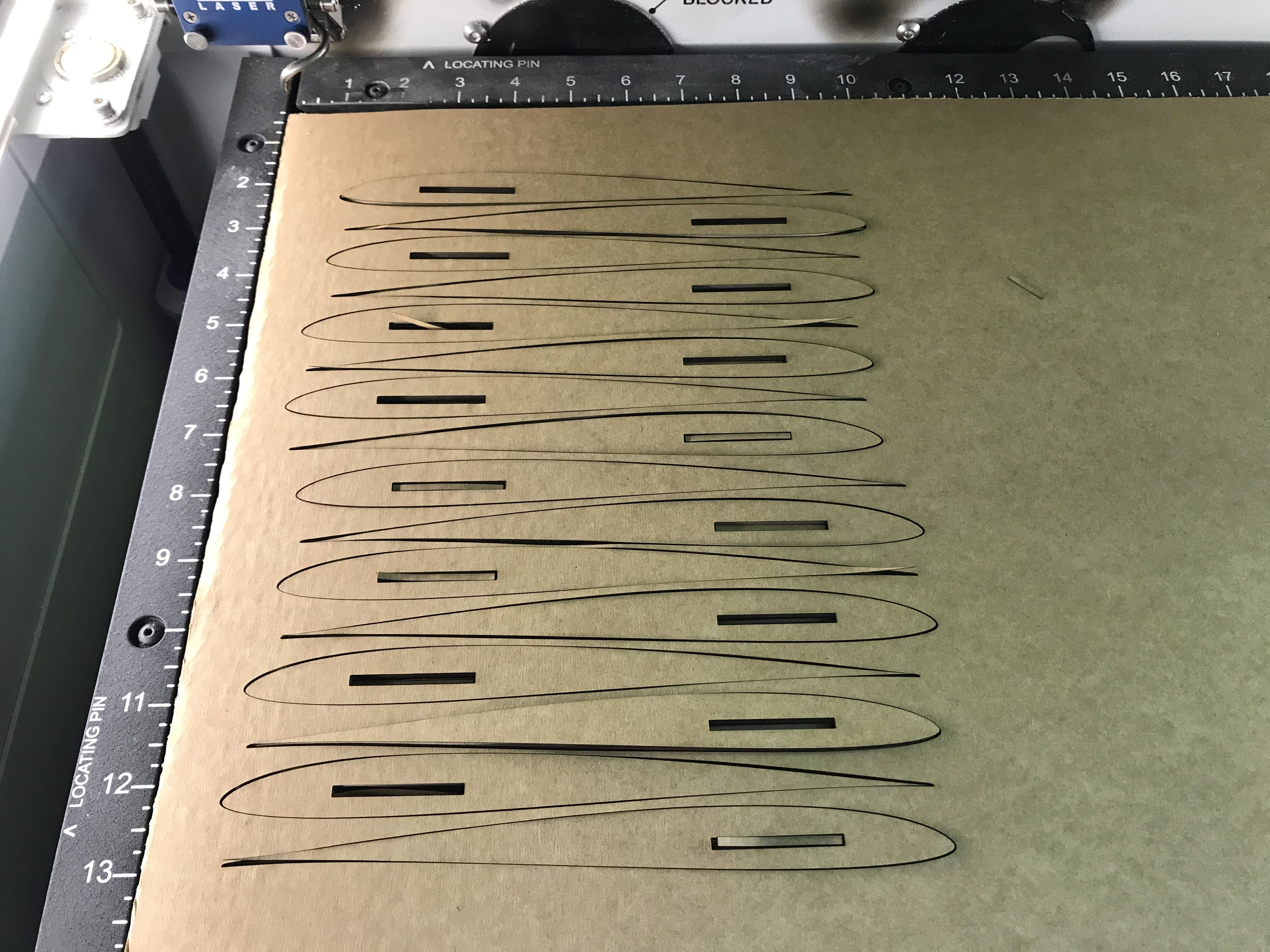
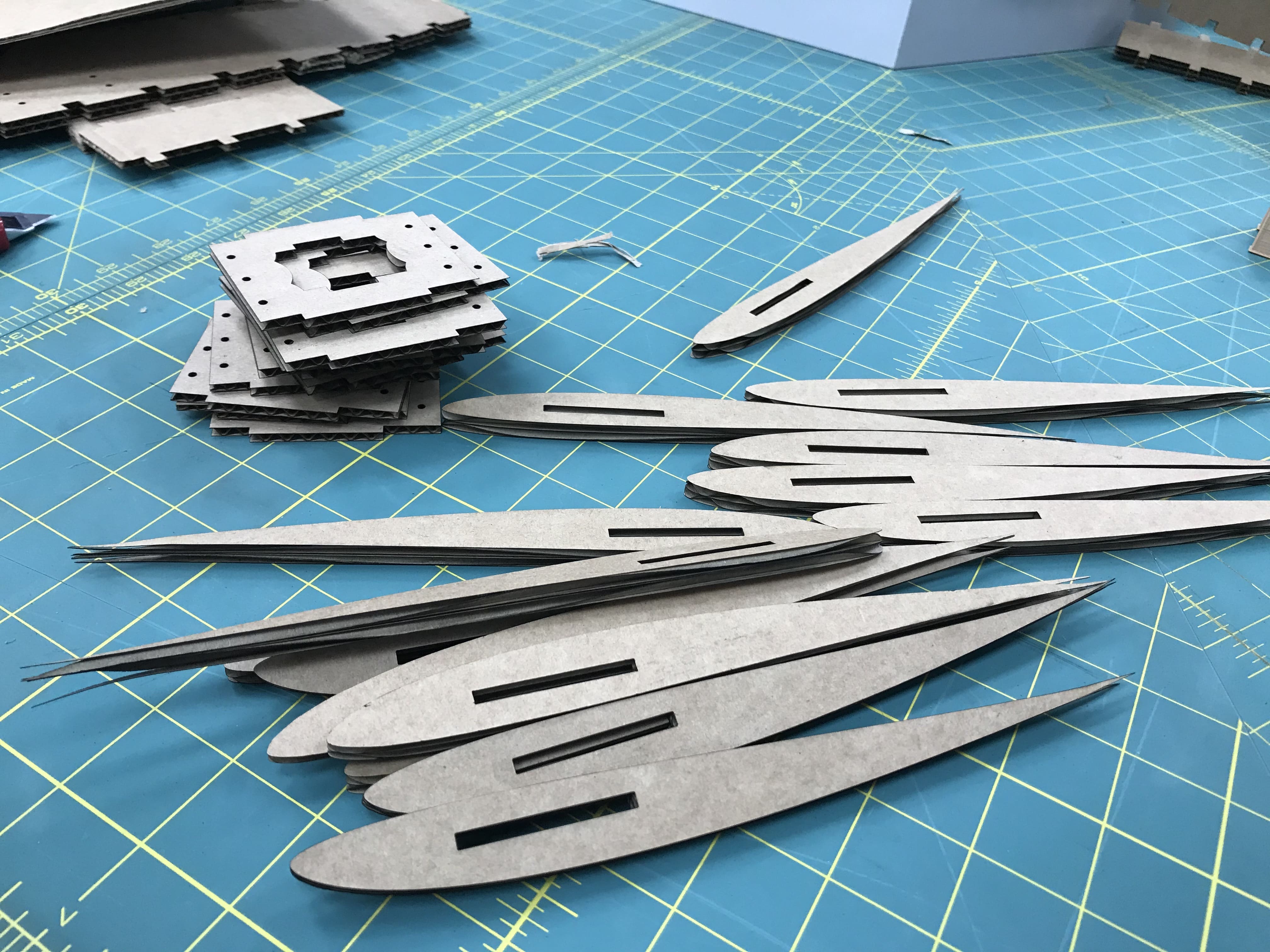
Cutting and assembling the airfoil
- First a whole bunch of airfoil segements were laser cut
- then the connectors and the motor mount were 3d printed
- the long wooden connector was laser cut
- Finally assembling the all the peices
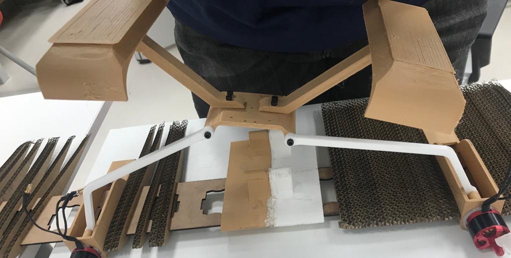
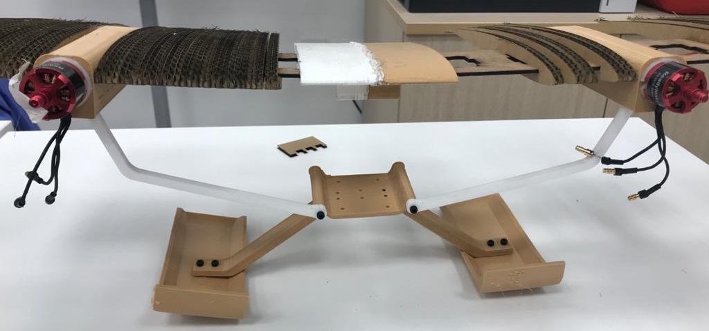
The landing gear and struts:
at first I was gonna go with the tyoical wheels landing gear but then I looked up the weight of the wheels I decided to for skies becuase it is much lighter and it is easier to fabricate.
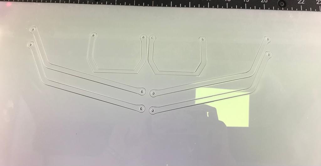
- first I designed these struts to support the motor weight:
- I used the laser cutting rather than 3d printing to fabricate the struts because the material is quite rigid and I saved alot of time
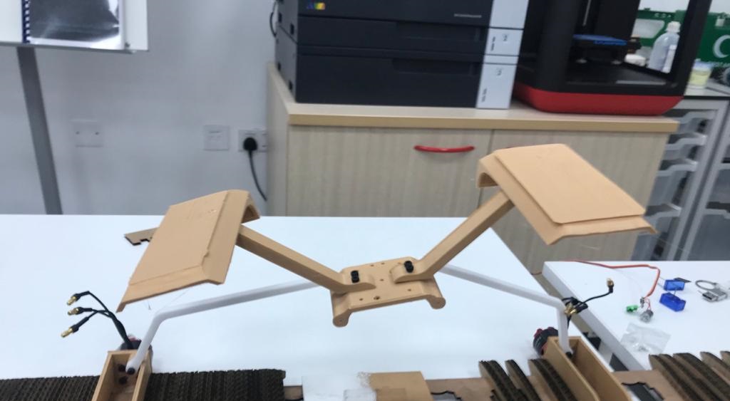
- then I designed the landing gear then I 3d printed both the skies as well as the legs:
- This is how it looks when combing the two together:


Simulation:
the design part is done so I am going to leave you with this cool simulation video:
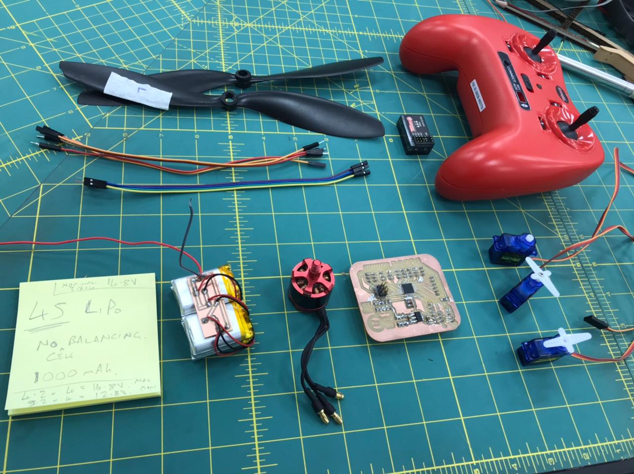
The electronics
so, in order to satisfy the final project requirements, I designed a board that has both input and output devices. for the input we have a reciever to controll the output devices, and for the output I have two brushless motors and 3 servo motors as well as leds.
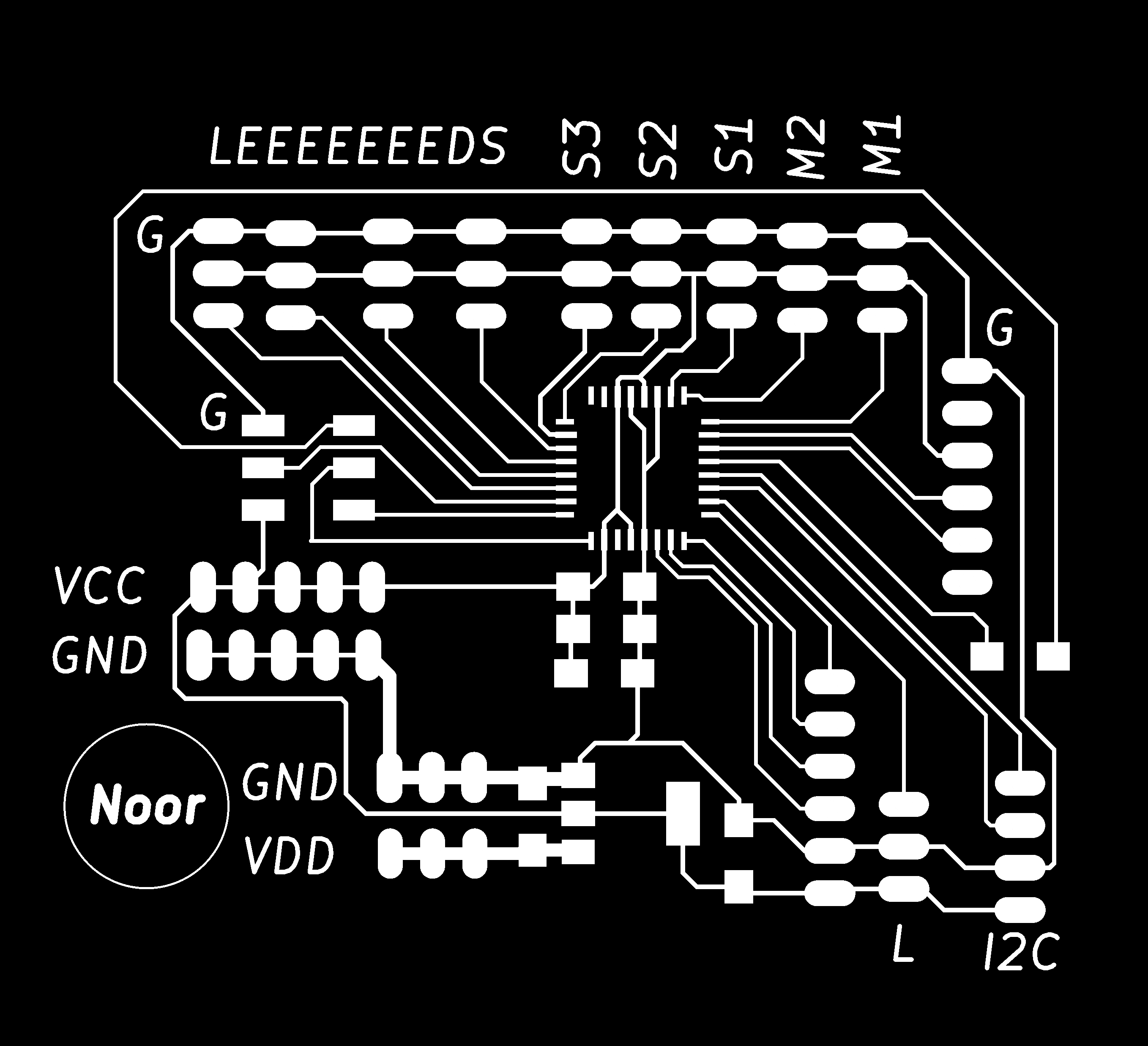
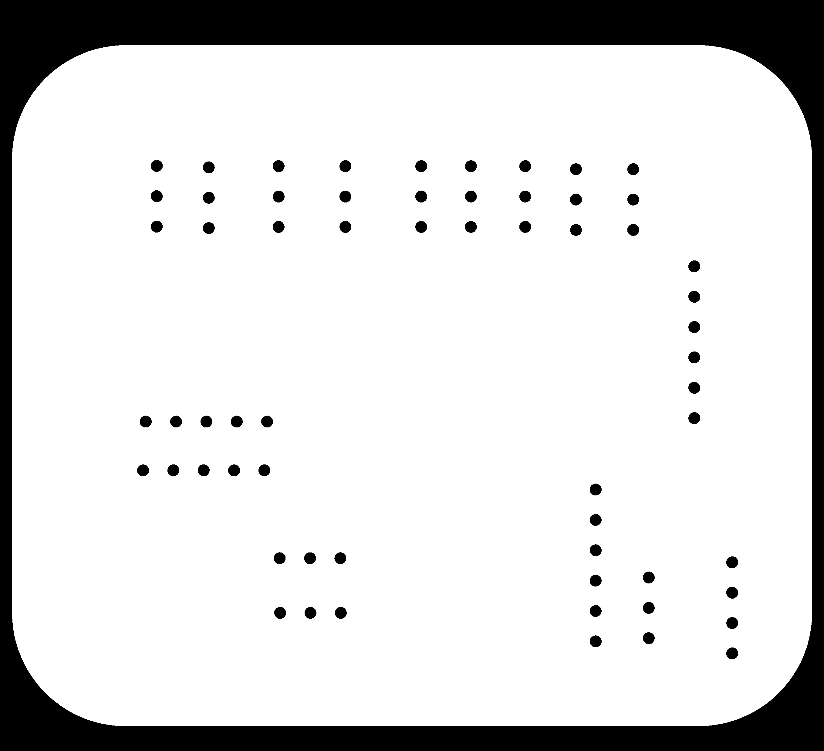
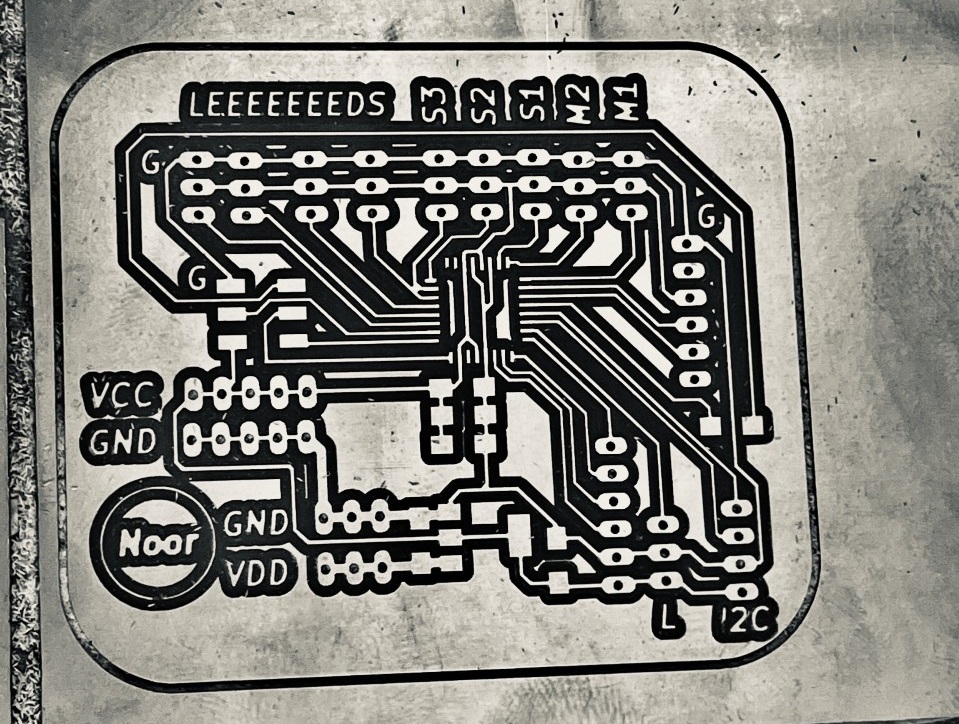
- Board design:
- This is the schematic of the final project board :
- connecting and all the parts together was a bit of a challenge since this was my first time using atmega32 so I took me some time to wire everything up
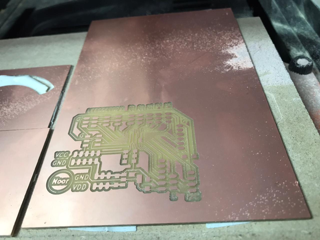
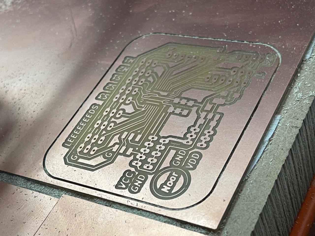
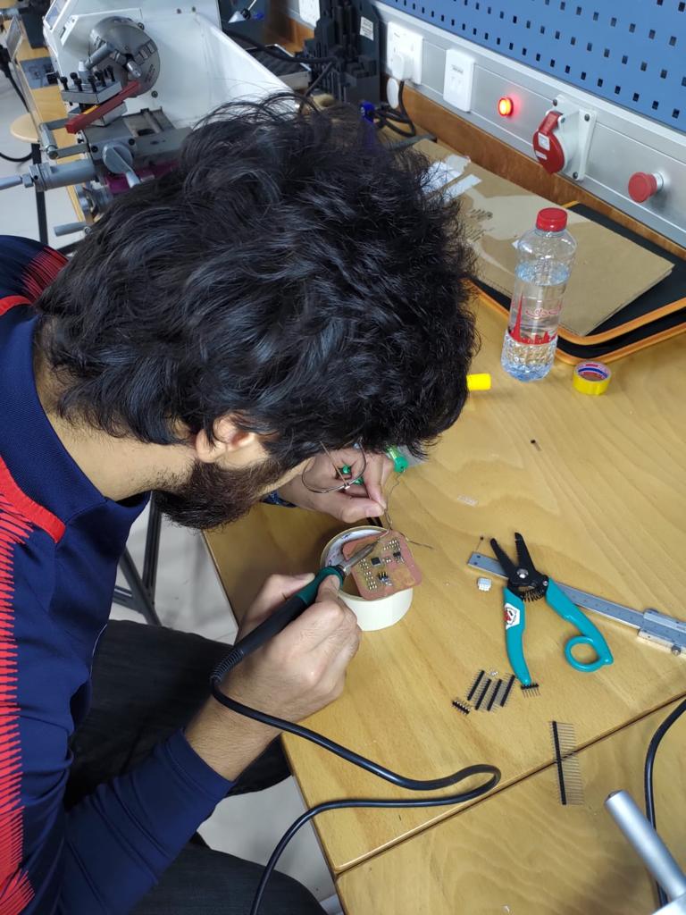
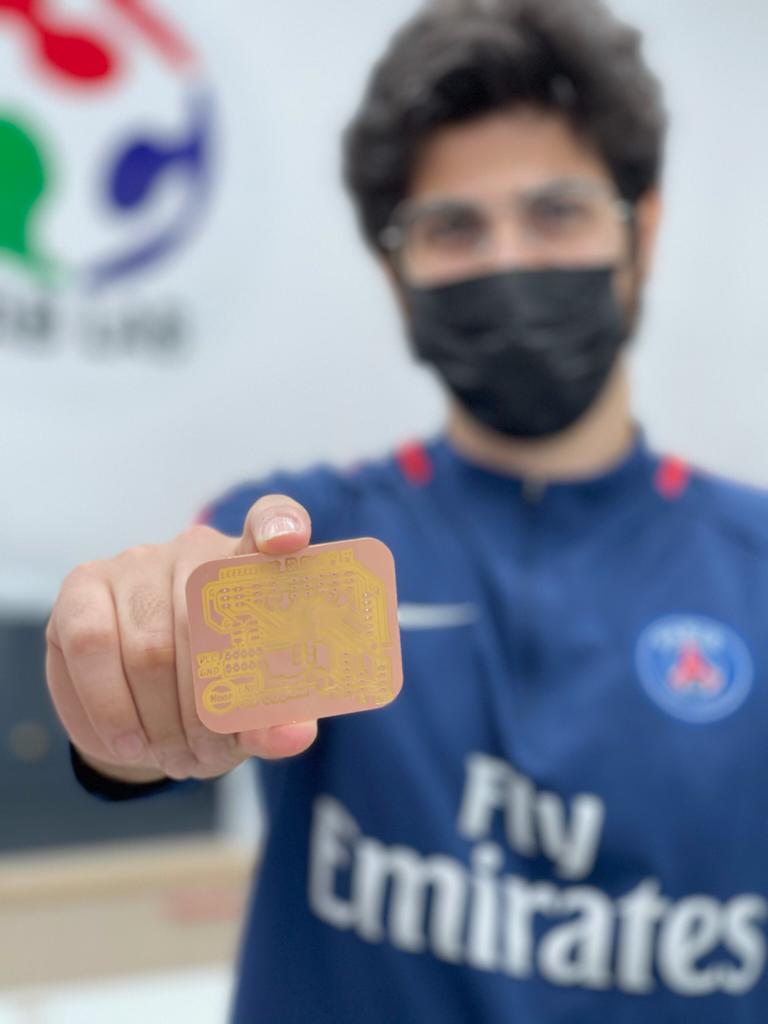
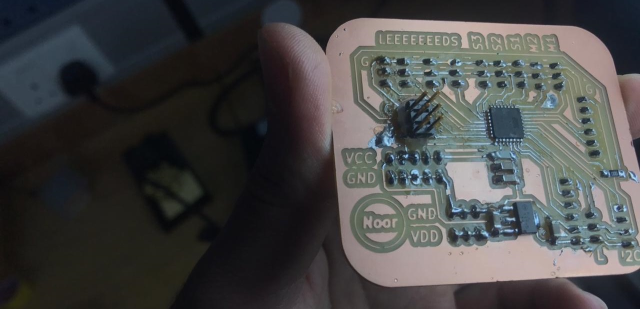
- Milling and stuffing the board:
- Milling the board is as satisfying as it gets , and it did not take time for me to prepare the png files for milling since I have already done this like 3 or 4 times.
- Some Satisfying videos and pictures of the milling process:
- soldering was pretty quick at first and then I realized that the order of soldering the components was wrong because I started soldering the pins first then the components and it should be the other way around, but evantually I pulled it off and the board is ready to be programmed.
- Programming the board:
- before programming the atmega I had to do some modification the board.txt file to change the clock speed to 1MHZ.I basically duplicated the Arduino Pro or Pro Mini settings and changed the build.f_cpu to =1000000L. if you are having problems changing the value just replace your board.txt file with this file.
- My instructor carl created a code to control a servo using the transmitter so I took this code and edited it to match my pins. the only problem that I had was the trasmitter was quite noisy so I had to implement an average function to smooth out the signal and it worked but in a perfect way.
- this is the arduino code that I used to control my airplane.
- testing the motors:
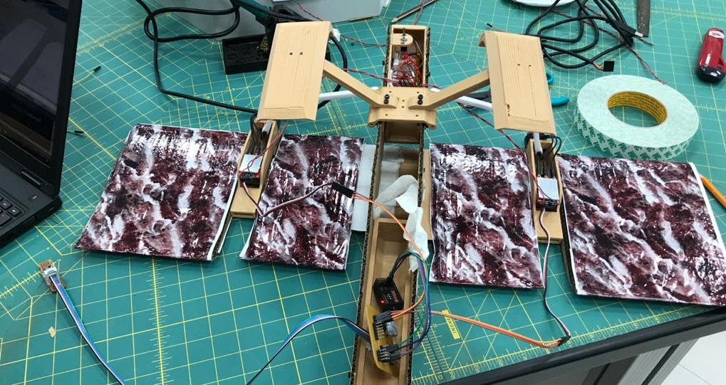
- Then I welded the two sigments of the wing and stacked up cardboad airfoils shapes as well as the 3d printed motors mount.
- Then I assembled the landing gear and bolt it with the wing to see if it is stable before adding the body of the airplane.
- After that I added the body and ready to get started with the electronics.
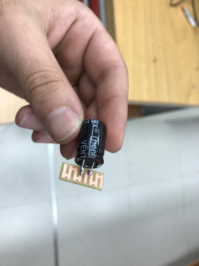
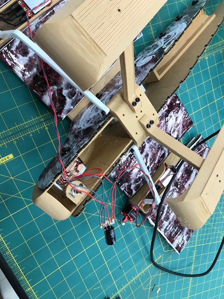
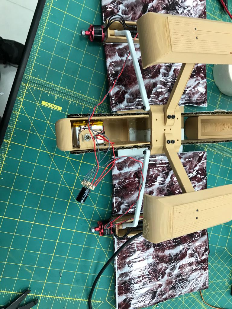
- For the electronics I created this little Power Distribution board with a capacitor so I can have a better wire mangement:
- Finally I connected the little board to the battery and then the motors and my board is connected to the Power Distribution board.
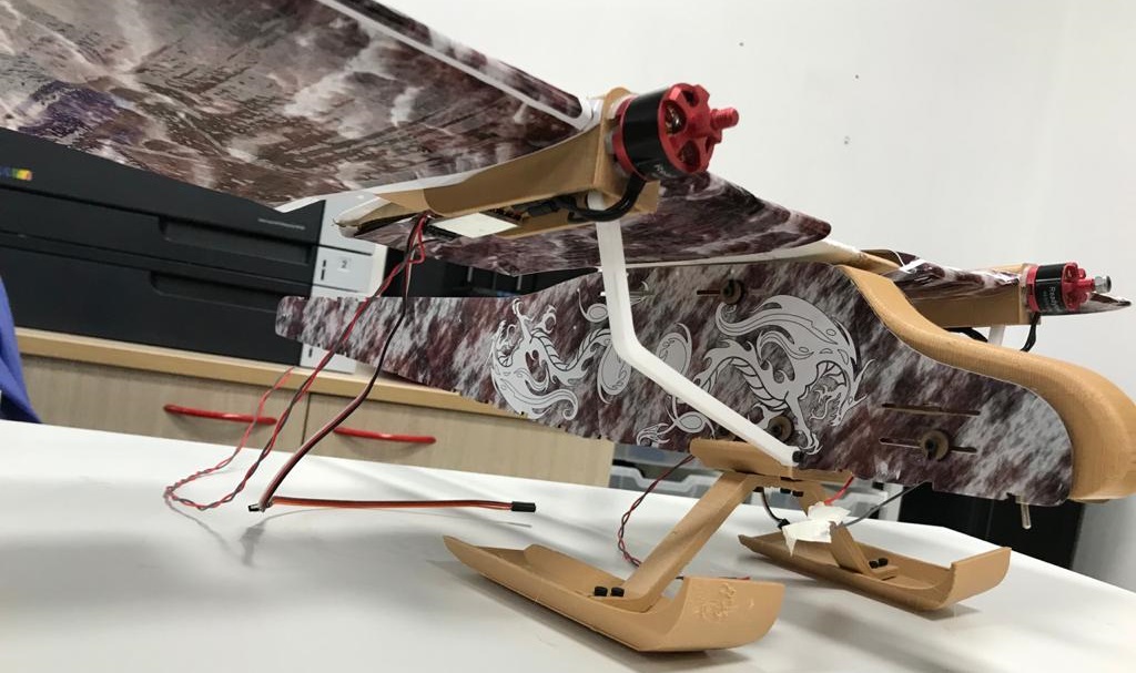
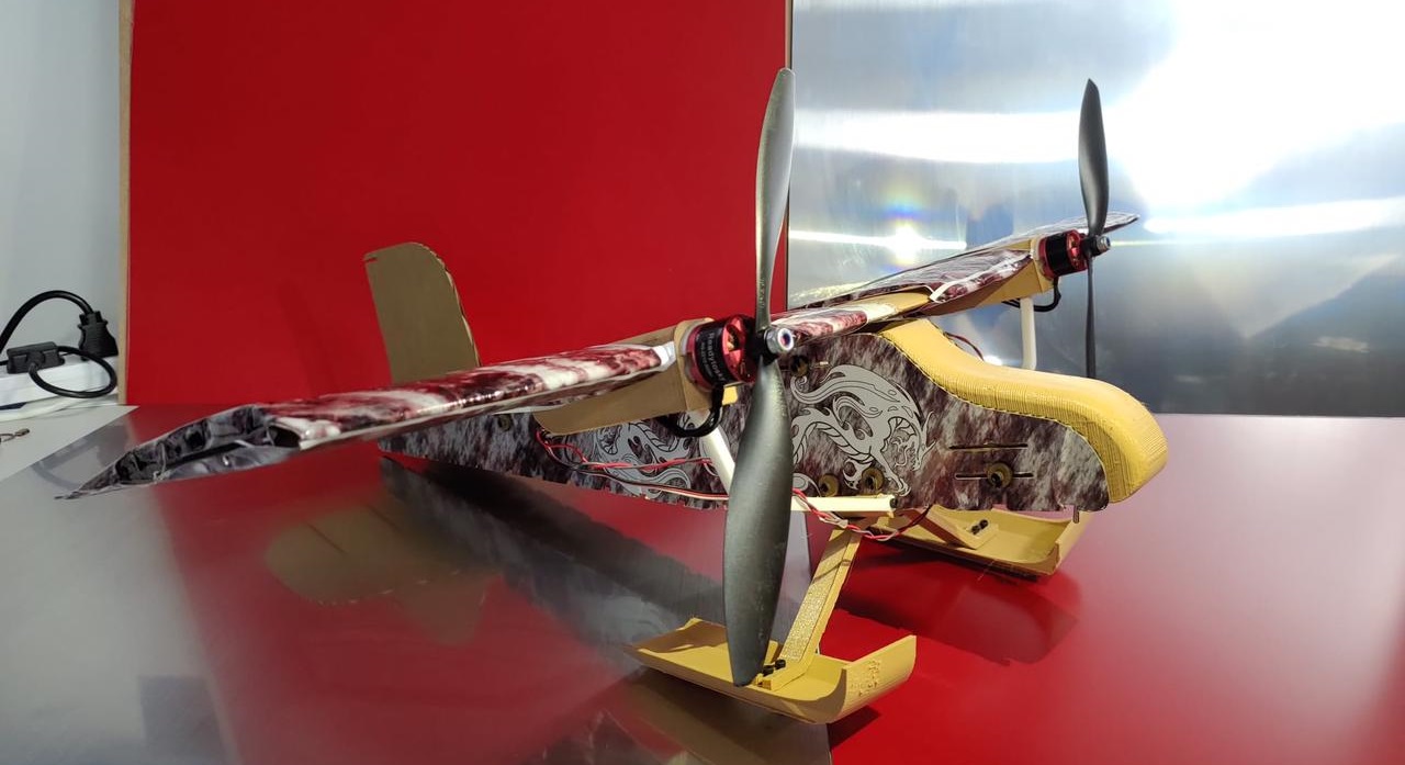
- Finally After Programming the everything and Installing the propellers it is ready to start experimenting on it.
I Decided to use atmega32p to make a board that connects all the output and input devices so I pretty much used all the pins in the micro-controller.


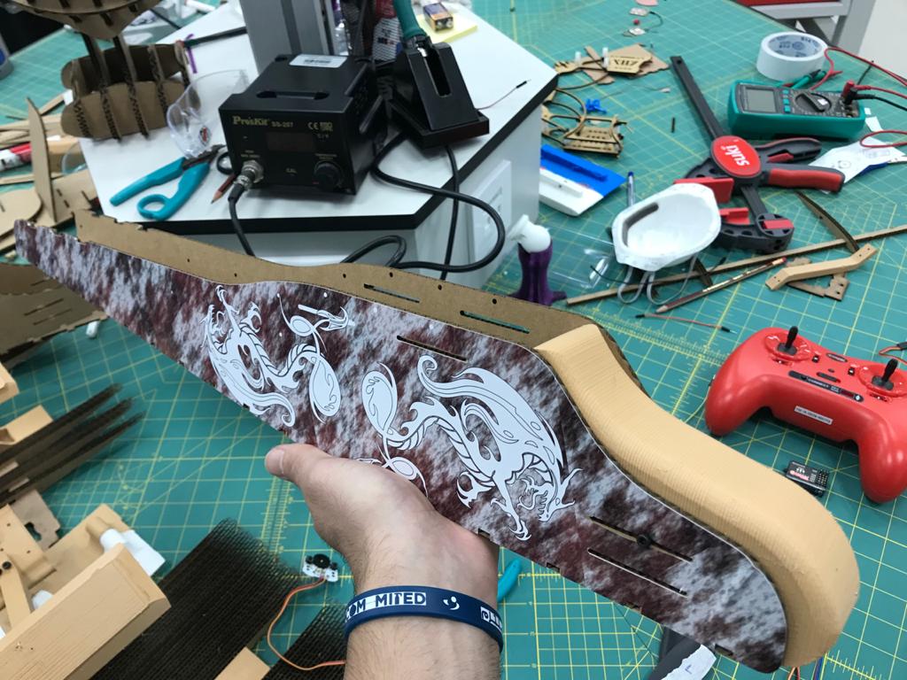
Final assembly:
- After cutting out the the main frame I printed out some stickers to make it look nice and clean: