Fab Lab ECAE
SRM 20 PCB Milling
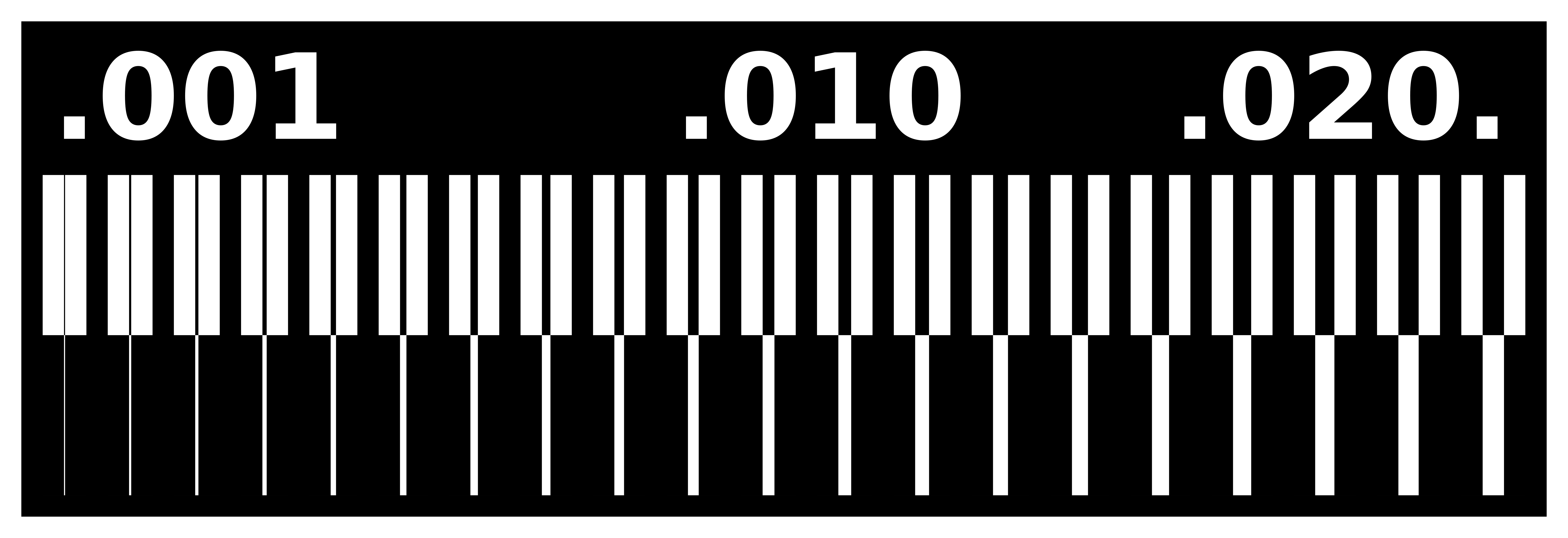
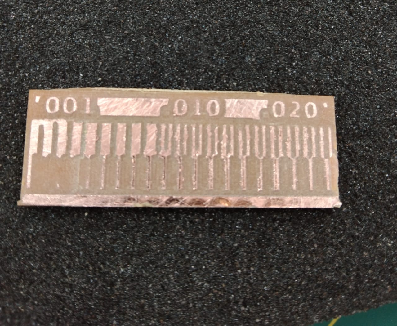
Using the SRM-20 for PCB Production: Characterize the design rules for your PCB production process: document feeds, speeds, plunge rate, depth of cut (traces and outline) and tooling.Line test:

Downloading the PCB files
╭─━━━━━━━━━━━━━━━━━━━━─╮
─━━━━━━━━━━━━━━━━━━━─
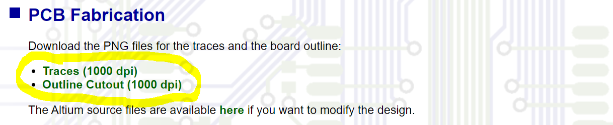
You can find the files on this page (PCB files designed by Mr. Brian).
╰─━━━━━━━━━━━━━━━━━━━─╯
Milling the pcb :
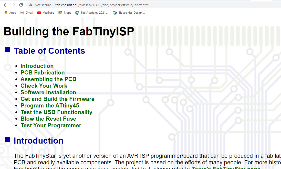
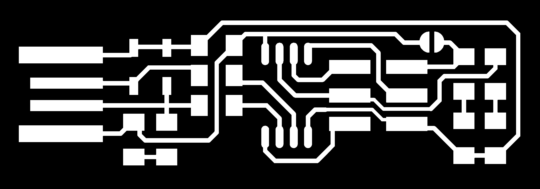
Since all we have is ATiny45 so I went for brian's ISP because it seems to be working for most people and it is very well documented, I began by downloading the PNG files for both the traces and the outline from brian's page :

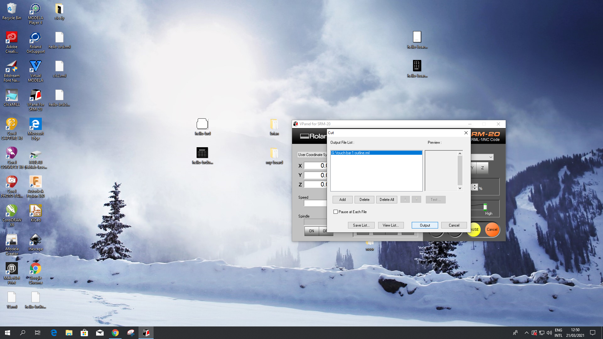
we have the roland SRM-20 in our lab and we will be using it for milling pcbs and molds:
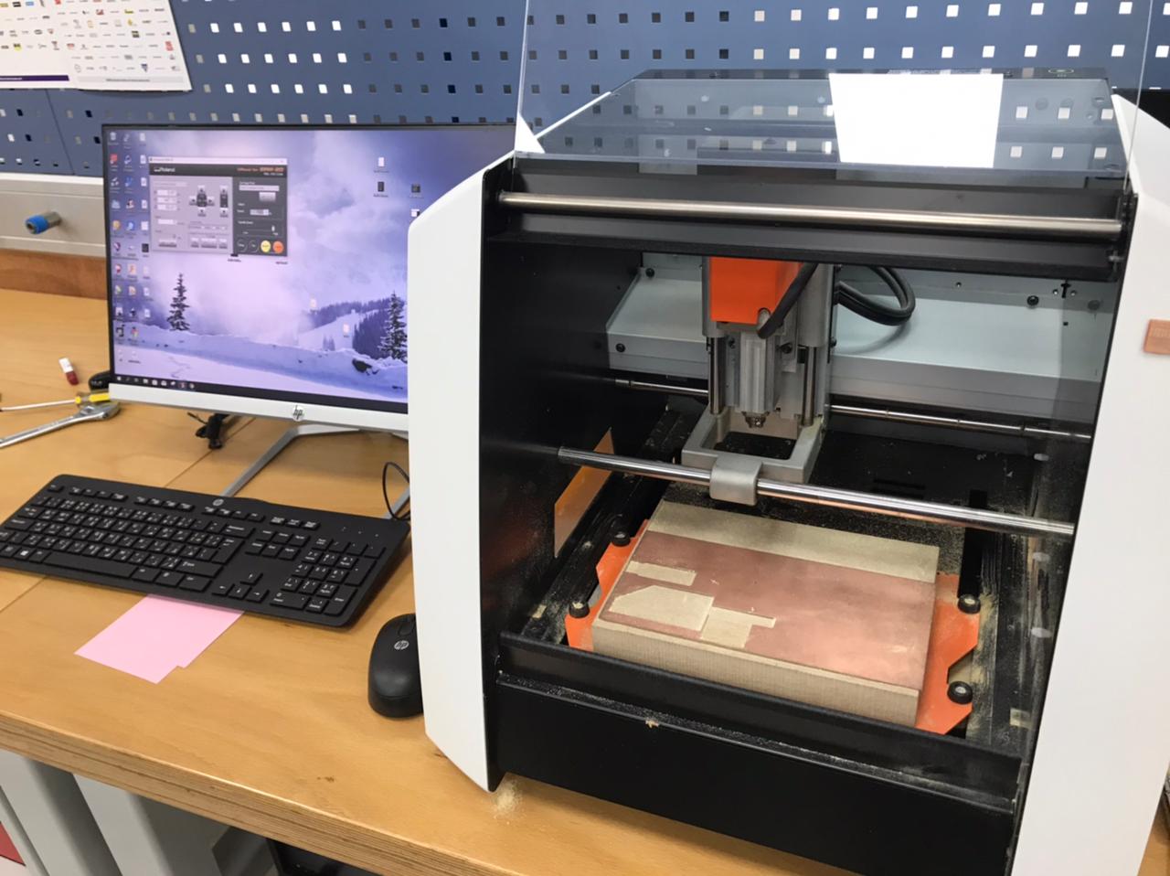
To use the milling machine, do the following steps:
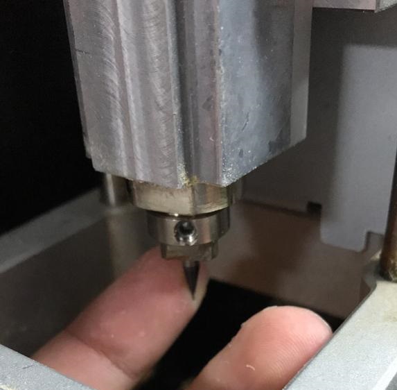
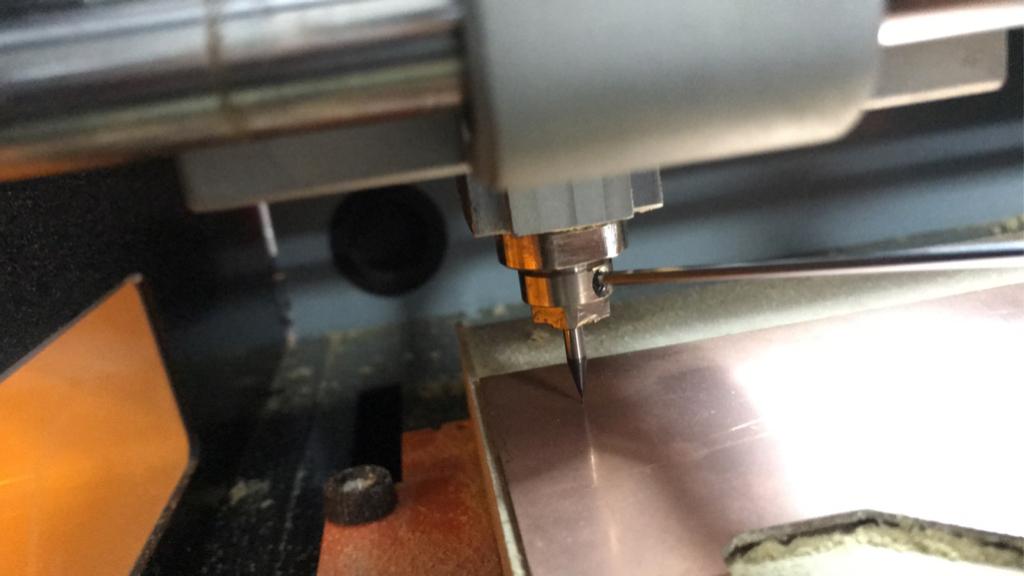
- First zero the z-axis and zeroing the z-axis is very important and It must be re-adjusted everytime the tool is changed , to zero the z-axis :
- change the tool and push it all the way inside in a way only the flute is visible
- carefully move it down using V-panel but do NOT let touch the cupper plate because some tools are very fragile , now adjust it manually so it is touching the plate
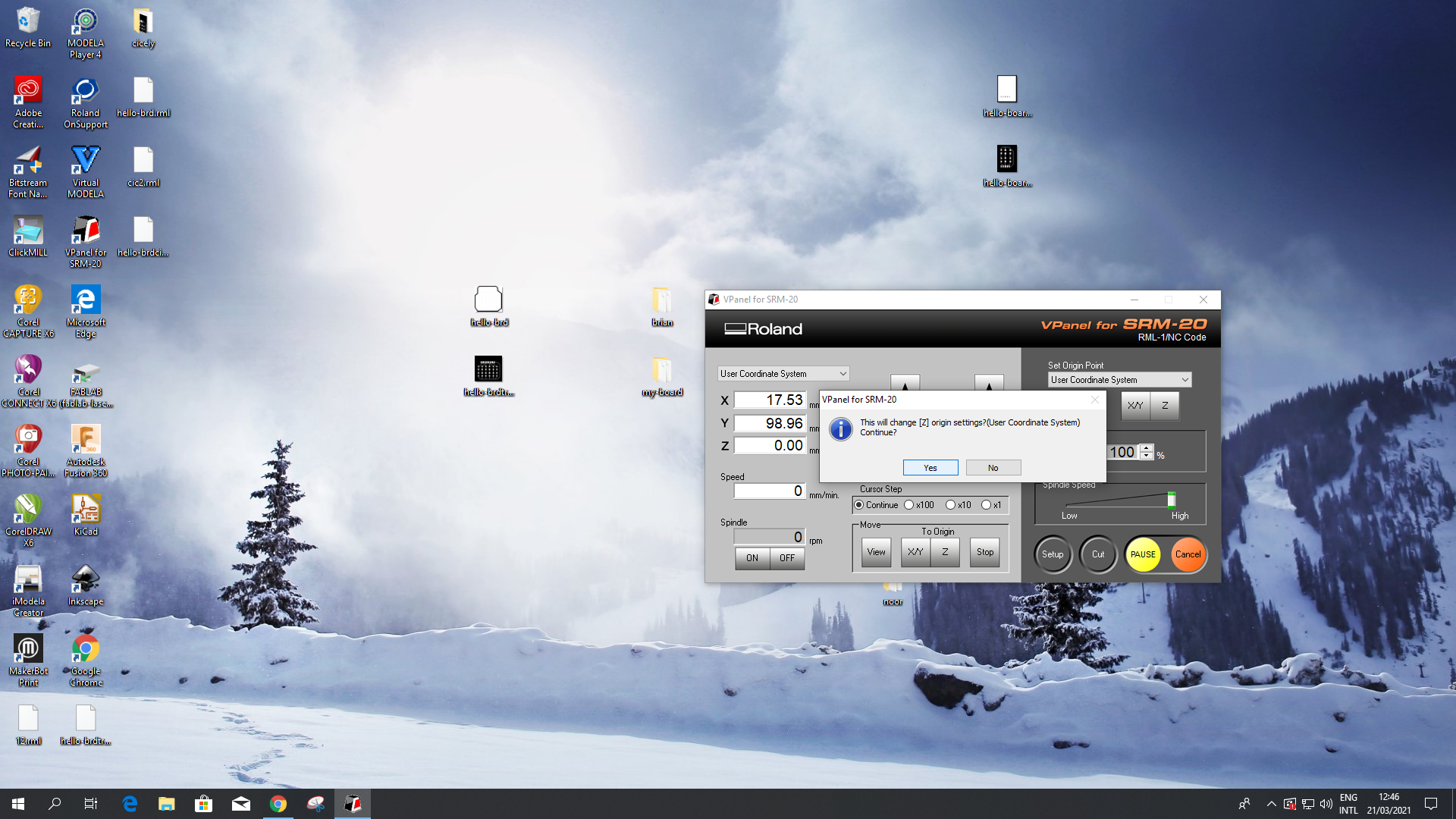
- finally set the zero origin for the z-axis in v-panel
- Zero the x and y axis by moving with vpanel but make sure that the tool is not touching the plate otherwise it will break.
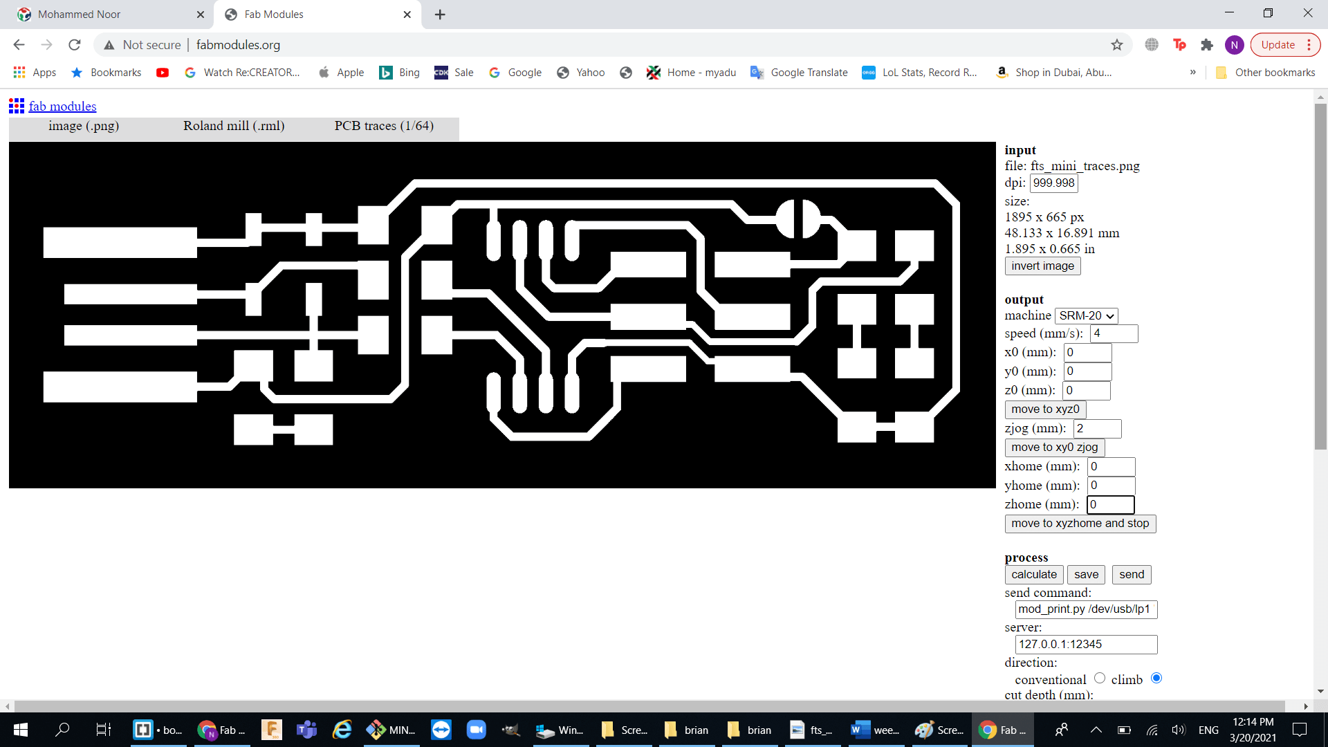
- Now go to fabmodules.org. this website calculate the tool path and gives you the file that is Compatible with your machine.
- Export your files and choose your machine and v-bit you are going to use
- Set the cut depth to what you want
- Now calculate then save
- Start cutting


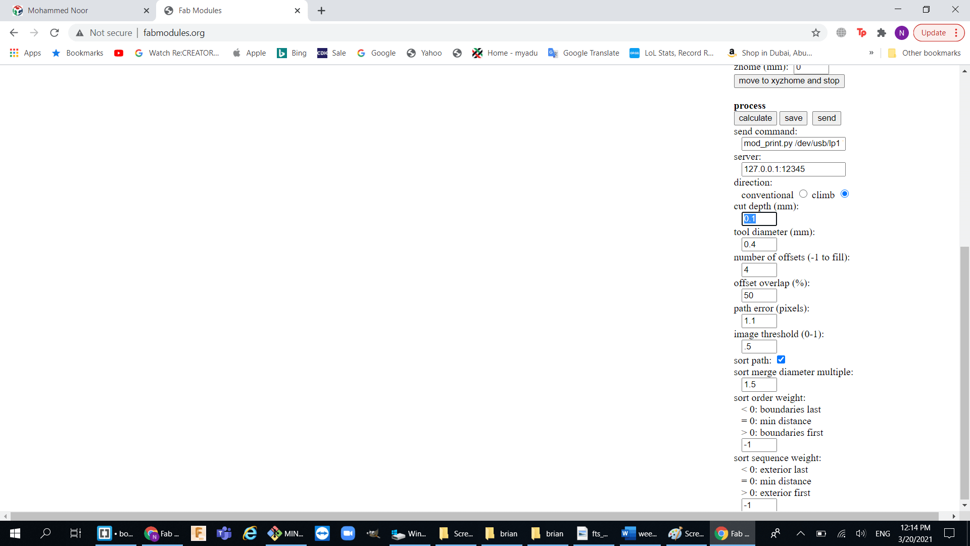
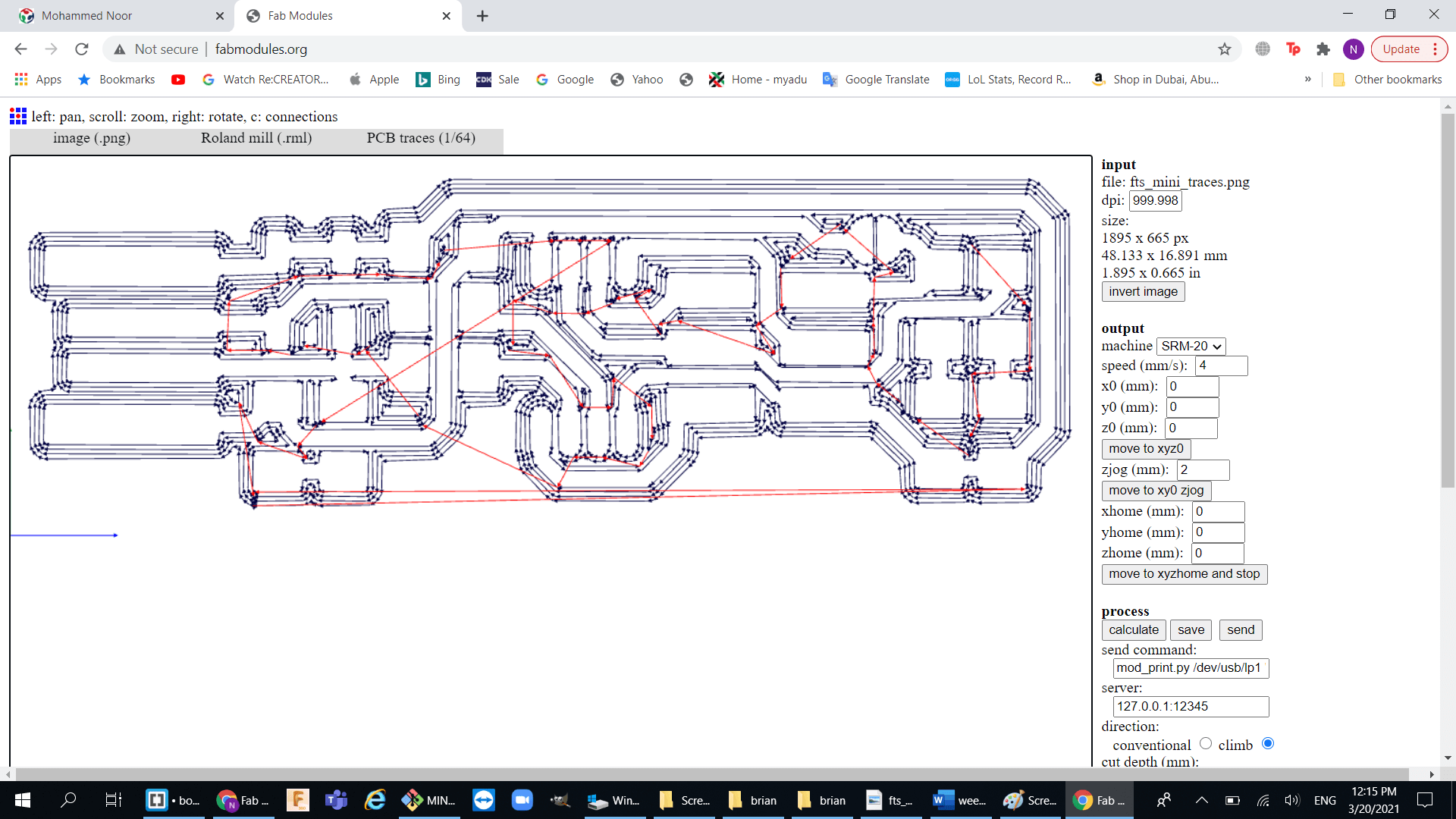
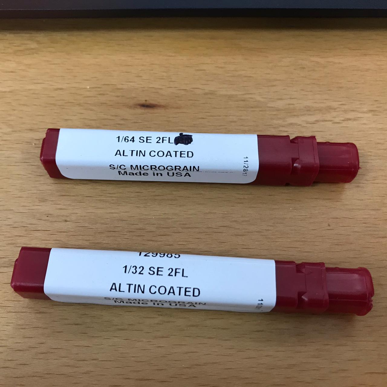
we used two kind of v-bits:
a. 1/64 for traces with 4 offsets and cut depth of 0.15 mm
b. 1/32 cutting with 3 passes and and total cut depth of 1.7 mm