Interface and application programming
This week Neil talked about interfacing, which refers to the interface between any two devices such as the laptop and a PCB as well as the interface between a user and a device. Many options of creating each were discussed.
The assignment for this week is to write an application that interfaces a user with an input &/or output device that we made.
The breadth of the information presented can be reviewed. There were two specific tutorial for two specific languages he recommended as worth learning:
- Python ("a beautiful language which combines the spirit of the best of LISP, C++, and APL")
- JavaScript ("to be web native"
Neil also mentioned APL being his favorite language, which was more for math notation. And said MIT App Inventor or mods would also be good options to get this week's assignment done.
Here Nadieh Bremer is presenting an intro/overview of D3.js for later reference.
The ESP8266 Remote Control
This board was started last week during the networking and communications assignment. Last week I tried to control our Samsung air conditioner using the IR LED connected to an ESP8266 board, which was also made into a web server. Last week the control was done through an embedded program in the ESP8266 processor.
This week, I am going to add a DHT11 temperature and humidity sensor to the ESP8266 NodeMCU board and read the results. Then I'm going to add an IR receiver to the board, making it possible to read and decode IR signals from various remotes. And for the week's assignment, I am going to add a web interface for the user to be able to see the temperature and humidity readings when connected to the board through wifi, as well as be able to change the air conditioner settings or receive IR codes from other remotes.
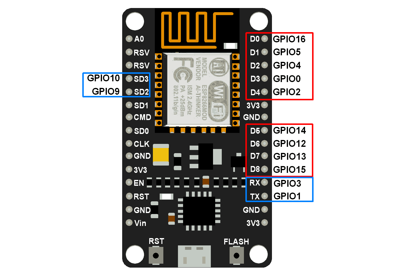
Here is the pin configuration of a NodeMCU v3 board; GPIO stands for General Purpose Input/Output, so each of the GPIO pins can be used for either of those. And the pin numbers used in the Arduino IDE correspond to these GPIO numbers. As will be seen later though, not all IO pins are created equal for various purposes :)
Adding DHT11 and programming
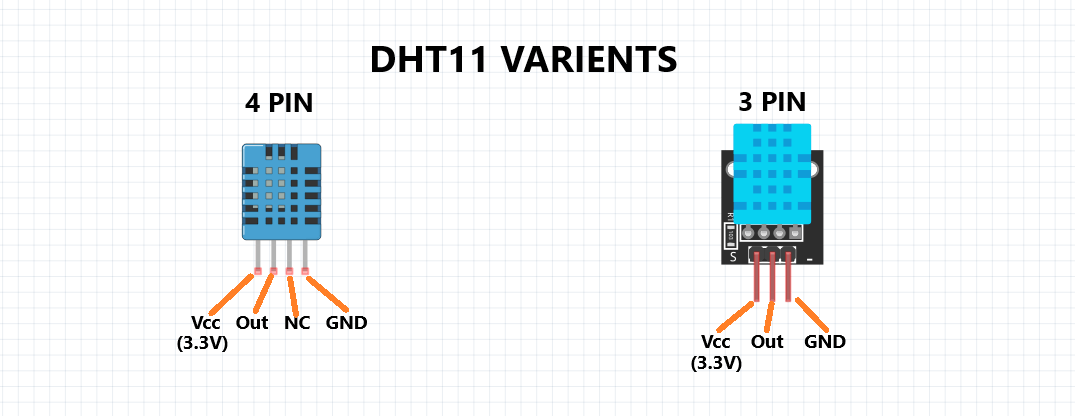
DHT's are low-cost temperature and humidity sensors with a capacitive humidity sensor and a thermistor. Inside there is also a chip that does analog to digital conversion and outputs the temperature and humidity as digital signals. DHT11 and DHT22 are popular models of those:
I decided to use DHT11 due to its availability:
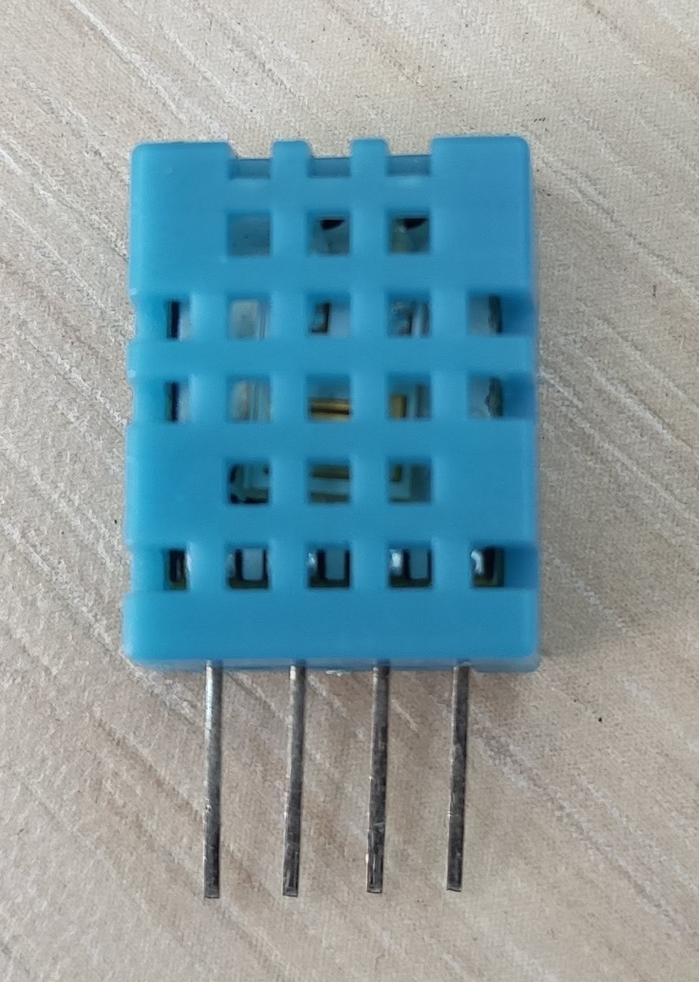
The DHT11 was set up on the breadboard:
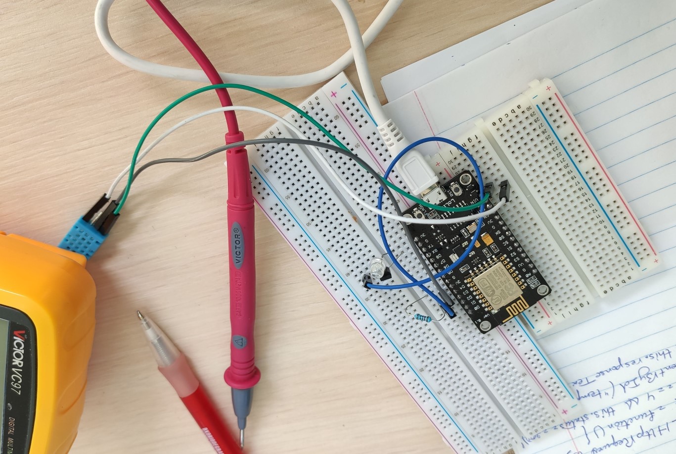
I uploaded the DHTtester example from the Arduino IDE, and it worked:
Adding an IR receiver and programming
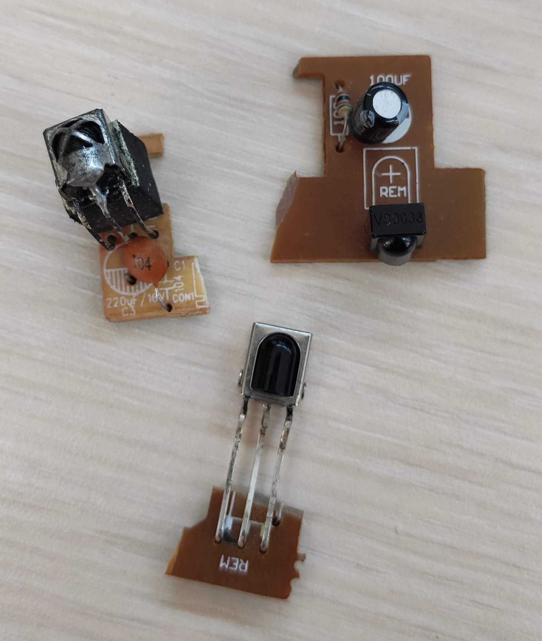
Since last week I've wanted to use IR receivers to decode various remote data and add them to my board. However, I couldn't find *just* the IR receiver from any electronic stores. It had really become a challenge. So finally, my nanny's husband managed to get some old IR receivers from the boards of some non-working old electronics from a local Dilijan electrician. I was super excited and my hat's off to them!
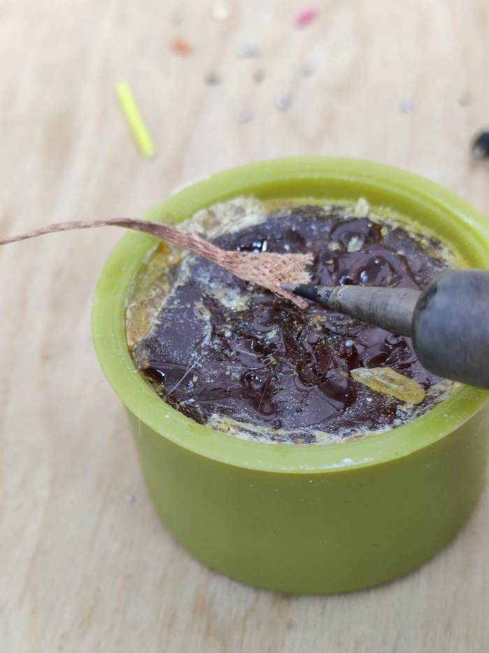
I had to 'unsolder' and detach the IR receivers, of course. So here's the trick I came up with: Take the copper solder wick and put it on flux and heat it up a bit for it to absorb some flux:
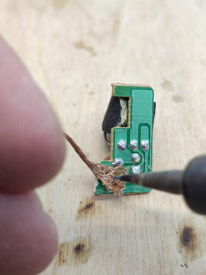
Then take that wick and use it to pull up solder from the old boards. It worked like a charm:
So I ended up with a beautiful CHQ1838 IR receiver, which I didn't know whether worked or not:
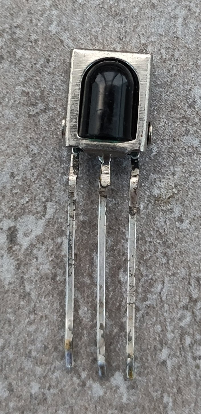
I found a little Chinese datasheet with the pin configuration of the receiver:
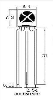
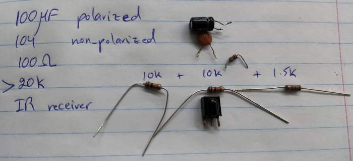
And the datasheet also had an application circuit diagram for the IR receiver, which interestingly, was very similar to the way the receivers were set up on the boards I recevied; and to the credit of the electrician who passed them off to me, he had included those parts, which included a polarized 100 μF capacitor and a non-polarized 100 nF capacitor that were connecting VCC to GND in parallel, so I think those were decoupling capacitors (why is one polarized and the other not? Still don't know.) There was also a 20 kΩ pull-up resistor:

I ended up 'desoldering' the other components from the old IR receiver boards as well to use in my own circuit:
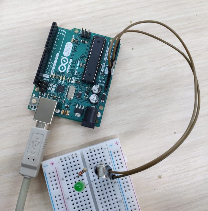
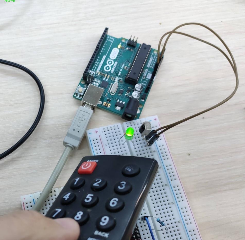
My initial tests weren't working, so I ended up looking online for a way to test and see whether my IR receiver worked at all, and found this wonderful test for the receiver. My IR Receiver was working:
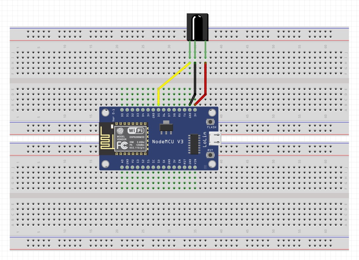
I tried again with the breadboard, and actually tried to see whether the receiver worked connected directly to the NodeMCU pins:
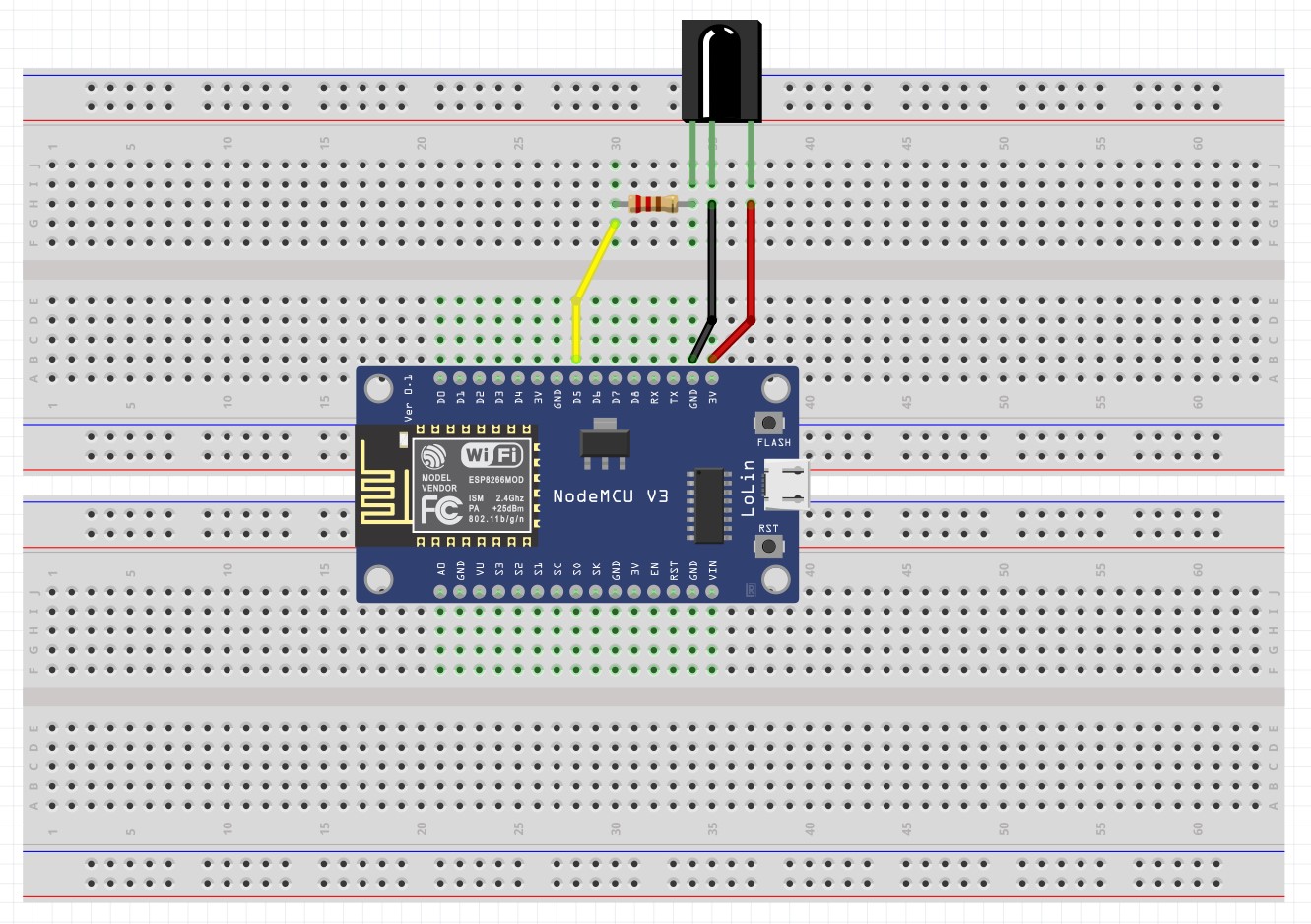
Then I tried to see how it worked with a 200 Ω pull-up resistor:
And then I tried it with the suggested application diagram from the datasheet:
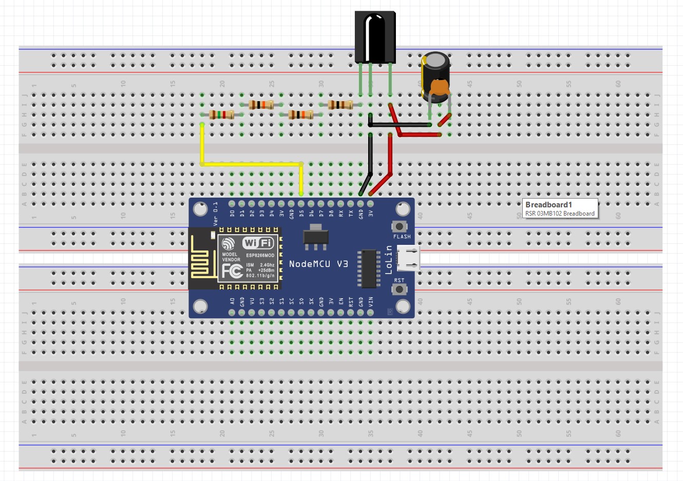
These schematics, by the way, were created using Fritzing,
which I've become a fan of. All three setups seemed to work fine using File -> Examples -> IRremoteESP8266 -> IRrecvDumpV3.
Creating the board
Design
I designed my board to accommadate the IR emitter, IR receiver, and the DHT11 sensor using KiCAD.
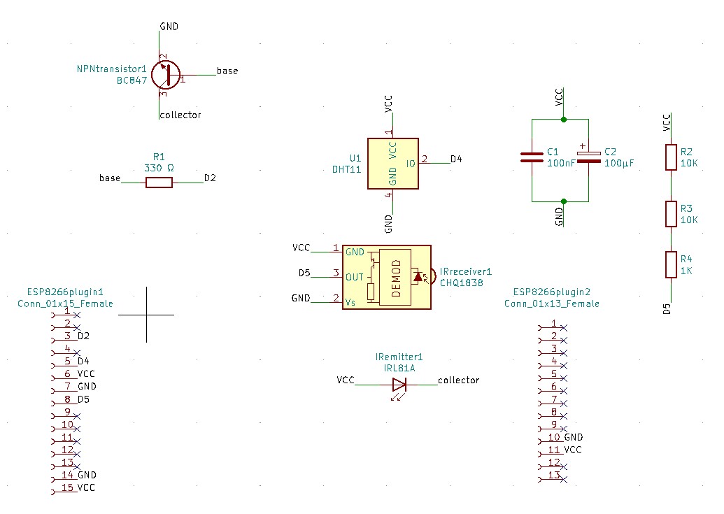
Here are the footprints for the components that I used in the design based on what was available (including the older components from the IR receiver boards):

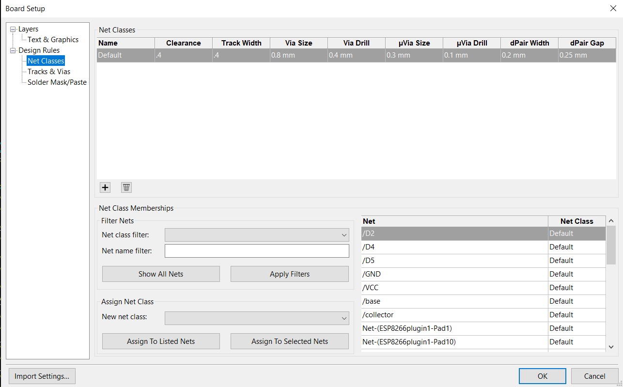
Then I tried to created the final PCB design with the following rules for the traces (in KiCAD):
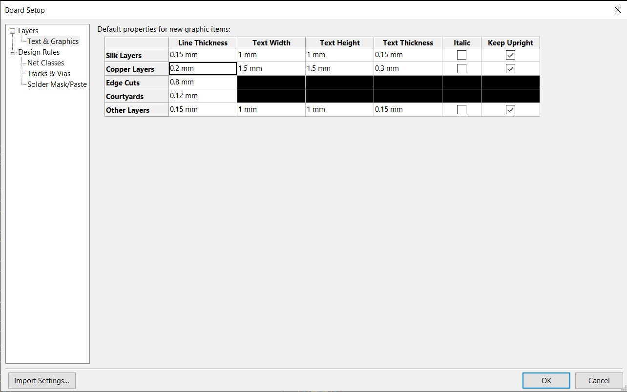
And here are the rules used for the edge cuts:
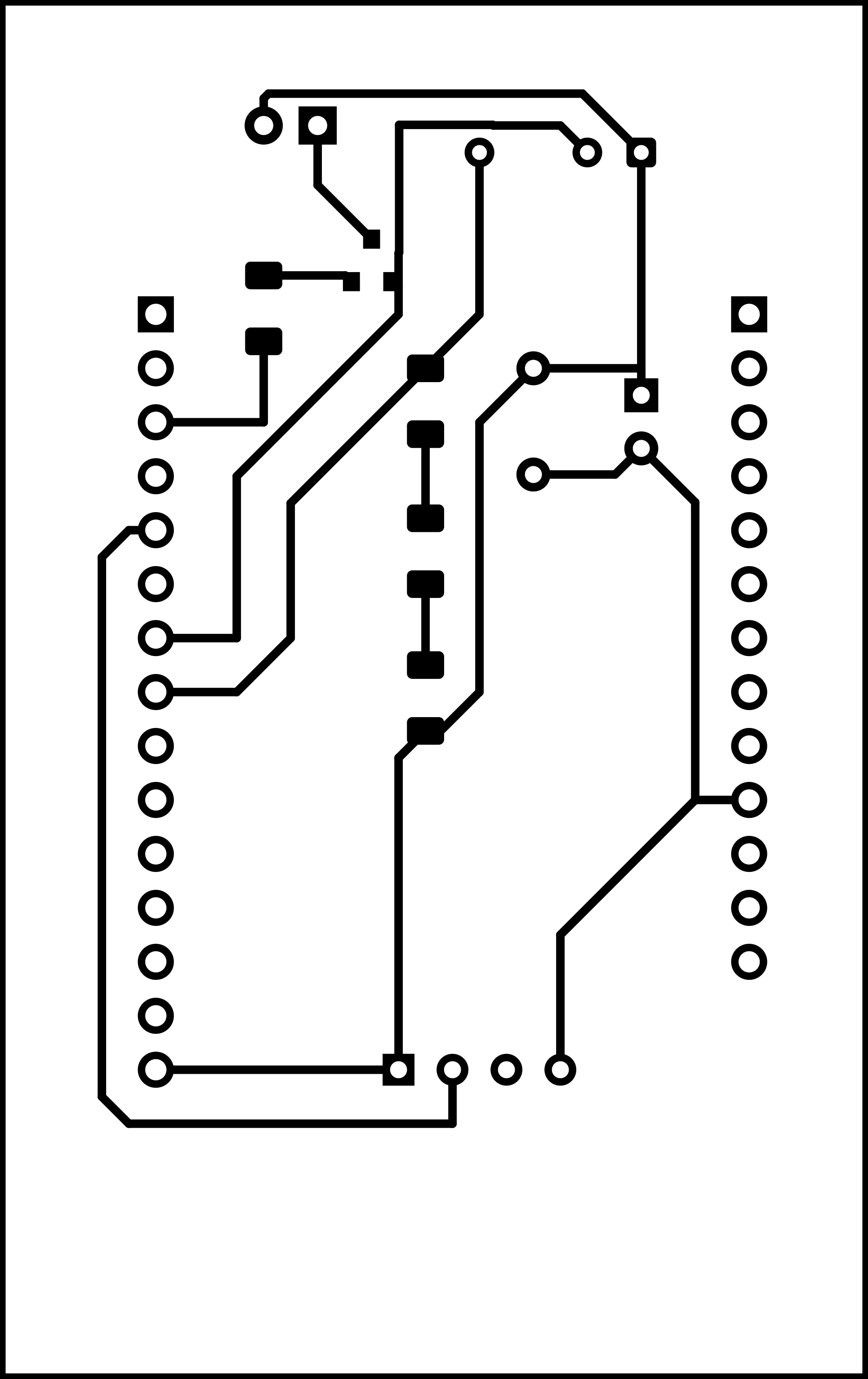
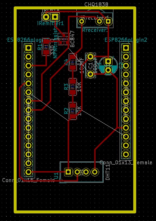
And the final PCB diagram:
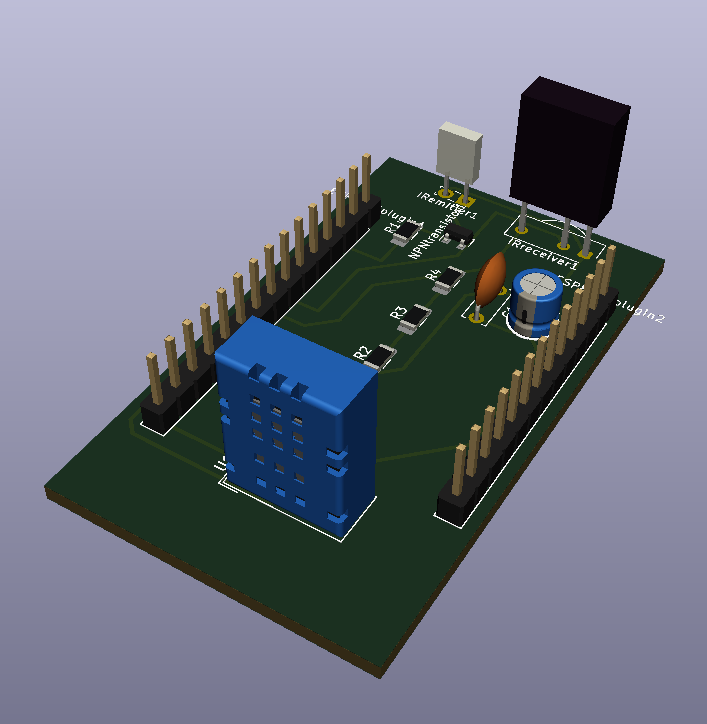
Here's a 3D view from KiCAD through View -> 3D Viewer.
Milling
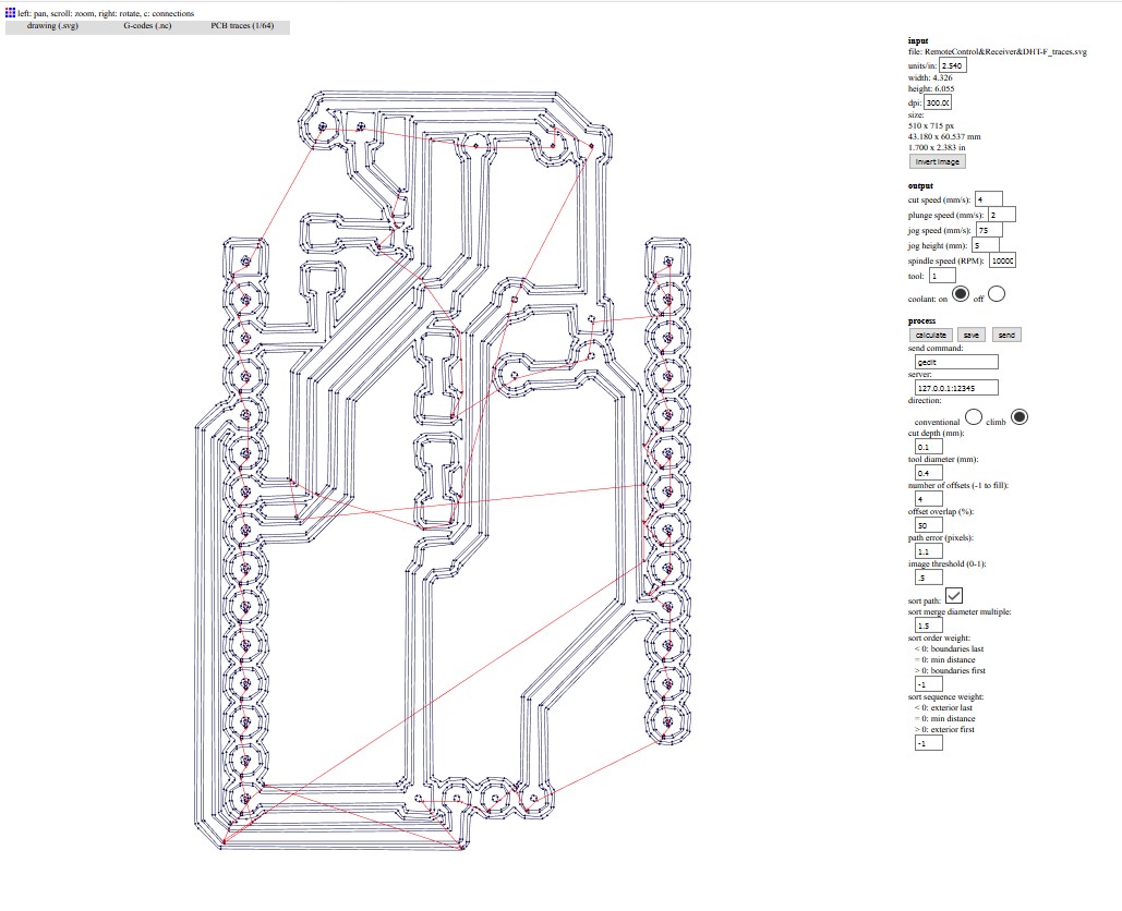
The traces were created using fabmodules.org which is the older (but simpler) version of modsproject.org/:
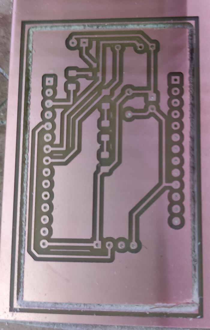
The board was milled using the .nc code generated by a Roland SRM 20:
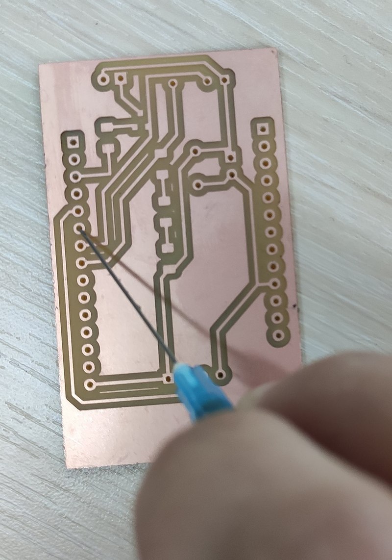
The vias, though milled, seemed a bit closed off right at the bottom, so I used a medical needle to open them up:
Soldering
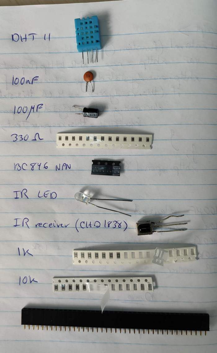
Here are the final components of the board:
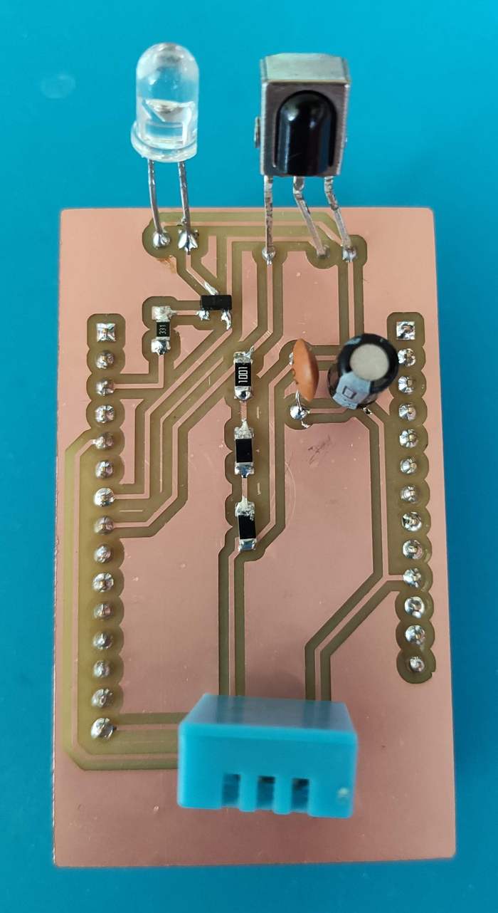
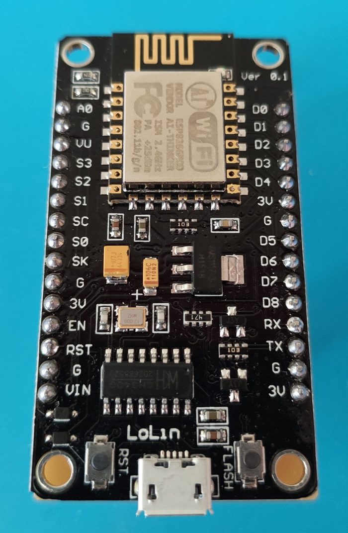
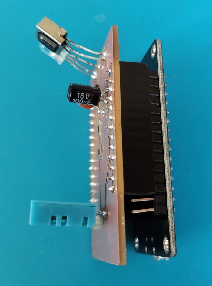
And the final result from various angles -- the male headers from the NodeMCU fit perfectly in the female headers I had soldered on my board:
Testing the board and troubleshooting
I tested the board separately for each of the following working using the Example files from Arduino IDE:
- For testing the IR receiver I used
File -> Examples -> IRremoteESP8266 -> IRrecvDumpV3. It worked like a charm. - For testing the IR LED I used
File -> Examples -> IRremoteESP8266 -> ControlSamsungAC. This was also working well, but it really depended on the angle of the IR LED pointing to the air conditioner. Distance didn't matter as much as the angle. My husband suggested putting a piece of scratched/sanded transparent plastic in front of it in order to act as a diffuser and reduce the angle dependancy. - For testing DHT11 I used
File -> Examples -> DHT sensor library -> DHTtester. This started malfunctioning in the beginning, sometimes failing to read the sensor, and sometimes providing completely off data:
I initially thought it might be because of damaging the sensor by soldeing, especially since I had touched the sensor itself couple of times while soldering, smelling the plastic. Someone at a forum had also quoted the following from the DHT11 datasheet:
"Welding temperature should be below 260 °C and contact should take less than 10 s."
That was definitely not the case for me. However, once I tried to upload the code again, the sensor starting functioning alright:
So I took a better look at the board. See something missing?
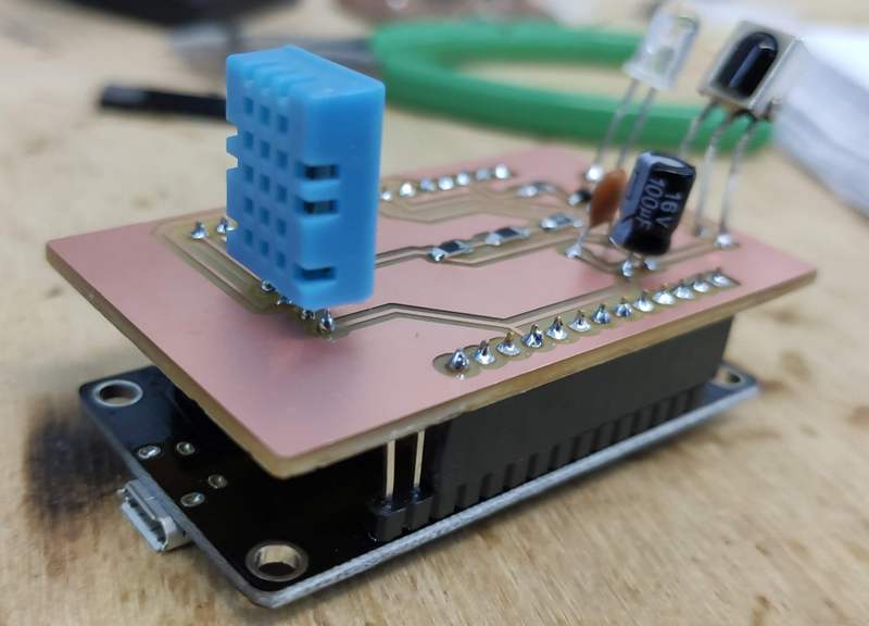
That's right: I had forgotten to put a pull-up resistor for the sensor. And I was in Yerevan and did not have access to a 10K SMD resistor. So I ended up detaching a 10K resistor from my output devices week and tried to fix my board by soldering it between VCC and D4 (the data pin for the sensor).
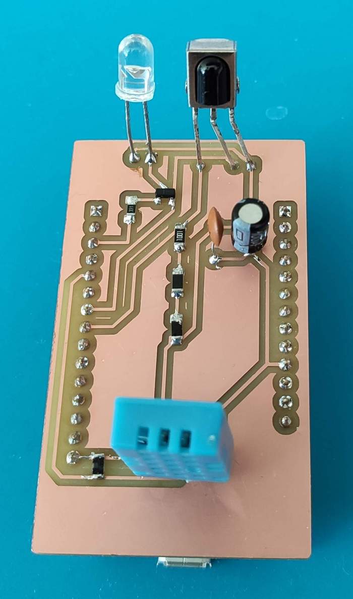
Once I tried again, the board was working like a charm. I should also remember to connect pin 3 to pin 4 of the sensor, to ensure the value at the unused pin 3 is not just floating and is grounded.
Another thing to notice is that after running a while, the ESP8266 is perceivably hot. It should be drawing considerable current.
Creating the interface and troubleshooting
For the interface I decided to use the ESPAsyncWebServer and mDNS, the reasons for which are explained in this video. DNS or Domain Name Server will make it possible to assign a domain name to an IP address, making it a lot more memorable. However, the ESPAsyncWebServer didn't work (I could not connect to the access point I was creating from anywhere), and I decided to switch back to regular web server and leave it as such to go through the router instead of making ESP8266 an access point.
An interesting problem that occured while programming the board was that I put the sensore readings in a loop
with a delay of 2000 microseconds. Then when I tried to change something in the code and upload it again, it wouldn't
allow the Arduino IDE to connect to COM4 (the port where my board was connected). I think that was because there was
constantly information being transferred back to the computer, and the port of busy and couldn't upload the code
to the board. The solution was to use the FLASH button on the NodeMCU board. However, as anyone who
has tried it can assert, the button seems to do nothing. The trick is to press RST (reset) while
holding down the FLASH button, and this will flash the memory, allowing for a new program to be embedded.
Final programming of the board
Powering up the board
Throughout the programming, the board was powered through its mini-USB connection to the computer, or through an Arduino Uno.
For independent function, I wanted the board to be connected to another power source, such as a 9V battery. However, I read in a forum that a 9V battery has between 400-600 mAH of power with NodeMCU drawing a minimum of 35 mA with upwards of 250-300 mA during packet operations. Unless the NodeMCU is put in deep sleep, a 9V battery would only be able to run it for 10-15 hours. NodeMCU also draws over 300 mA at startup every time while negotiating a WiFi connection.
Alternatively, an 18650 3.7 V Li-ion battery includes 2500-4000 mAH, which could operate the board for 30-40 hours.
I decided on using a mini-USB power supply, as would prefer the remote to be constantly connected.
Downloading the files
The files for the NodeMCU remote control board can be downloaded here:
- The schematic of the board (KiCAD schematic file with .sch extension, 47 kB)
- Monochromatic image of the traces of the board -- should be inverted for milling (.png, 133 kB)
- Monochromatic image of the outline and holes of the board (.png, 72 kB)
