WEEK 10: Input devices
This week was basically about measuring something with a pcb we've designed.
Group assignment:
For the group assignment, we compared and shared the information from different kinds of sensors.
The outcome of the group assignment can be seen in Carla's website: http://fabacademy.org/2021/labs/barcelona/students/carla-molins/week10-inputs/.
That helped me a lot to understand how different kinds of sensors work, how they measure and how can we get results from them.
Individual assignment
This week I wanted to work with some sensors that could be useful for my final project. Some parameters I would like to measure could be temperature, humdity, CO2 or VOP.
Searching for what we have in the lab, I found some temperature and humidity sensors so I decided to test them.
The first one is a SHT21 (Humidity & temperature sensor)

I also found a DHT11, to measure also temperature and humidity

The last one is a Grove - I2C High Accuracy Temp&Humidity sensor based on the SHT35 sensor.


PDB design and production:
I decided to make a basic PCB with an ATTiny1614 with the all the pins to connectors in order to allow me to connect whatever sensor I want to the board. I also decided to put a voltage converter with a switch so that it's possible to make the microcontroller work either at 5 or 3,3 V.
I also wanted to try to make a double sided PCB, so I used this one to test that.
For the schematics design, what I did was basically taking all the pins of the microcontroller to female connectors except for the VCC, GND, RXD, TXD and UPDI.
I also have a 6-pin FTDI connection to get data through serial and a 3-pin UPDI connection to program the board. I also added a power LED.
For the regulator, as I wanted to be able to work at 5V and 3.3V, I used a switch that allows to change the voltage of the microcontroller switching between the main 5V voltage or the 3.3V output of the voltage regulator. The datasheet of the voltage regulator I used can be checked here.
I also added another connector to take GND, 5V and 3.3V for external inputs and outputs, and a Grove connector for I2C inputs and or outputs.

The pcb layout with the vias and the tracks in both sides:

The process I followed to mill the PCB was divided in 5 steps:
- Mill the traces with the 1/64 endmill
- I changed the endmill with the 1/32 and I milled all the copper remaining as I did and explained in the electronics design week
- Then, with the same 1/32, I milled the vias with another file created in modsproject with a png that only contained the holes.
- To end with the front side, I did the outcut.
- The last step was to flip the PCB taking care of placing it exactly in the same place in order to mill the back side. To generate the file to cut the back side is very important to remind to mirror the png before generating the file, and also when flipping the pcb in the cnc, to do it in the same axis. I milled the traces in the back with the 1/64 endmill and in this case I left the rest of the copper as it is on the back side. Afterwards I realized that It could be interesting to make all the copper in the back be GROUND.
The process of flipping the pcb:

After milling everything, I had to make the vias. For that I used the vias and the riveter we have in the lab. It turned out that the vias we had were 0,4mm diameter and the minimum hole I was able to make was 0,8 as the 1/32 is the only endmill that is long enough to go all the way through the pcb.
For that reason, the vias were a bit loose in the hole and the rivets were not strong enough because they bend inside the hole. It was not a big trouble in the end because I was able to solve it easily with a bit of solder in both sides.
Process of putting the vias:


The final result was satisfiying, very clean and neat:


In order to use the SHT21 sensor, I had to make a specific PCB according to the following scheme given in the datasheet:

The schematic layout:

The pcb layout:

Final result:

As I was using the milling machine, I also made a UPDI board with 3 pins (GND, VCC, UPDI)

Sensors testing:
First of all, I tested the base PCB and checked the voltage changing the switch between 5 and 3,3V


Testing the SHT35:


The first one I tested was the Seedstudio Grove I2C High Accuracy Temp&Humi Sensor SHT35, the datasheet of wich can be viewed here.
I followed the guide in https://wiki.seeedstudio.com/Grove-I2C_High_Accuracy_Temp%26Humi_Sensor-SHT35/
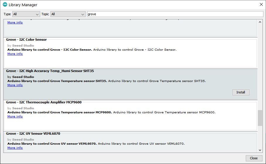
The first step was to install the library in Arduino IDE:

And then I opened the example given in the library:

But after choosing my board ATTiny1614, and compiling the code, I was given the following error:

So I decided to compile it and test it with an Arduino UNO to see if the code and the sensor worked. And they did. To do so, I connected the SDA and SCL cables with the proper ones in the Arduino board.

So I supposed that the problem was related with the compatibility between the library and the ATTiny.
Searching for more examples, I found this https://electropeak.com/learn/interfacing-sht35-temperature-humidity-sensor-with-arduino/ where they make it work with a library of the SHT31.
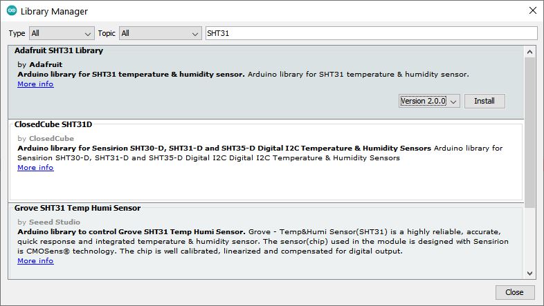
So, first I downloaded the library:

And then I copy-pasted the code in my Arduino IDE.
/*
 SHT35 Temperature & Humidity Sensor
 modified on 13 Oct 2020
 by Mohammad Reza Akbari @ Electropeak
 https://electropeak.com/learn/

 Based on Library Example
*/

#include "Wire.h"
#include "SHT31.h"

uint32_t start;
uint32_t stop;

SHT31 sht;

void setup()
{
 Serial.begin(115200);
 Wire.begin();

 sht.begin(0x45);    //Sensor I2C Address

 Wire.setClock(100000);
 uint16_t stat = sht.readStatus();
 Serial.print(stat, HEX);
 Serial.println();
}

void loop()
{
 sht.read();

 Serial.print("Temperature:");
 Serial.print(sht.getTemperature(), 1);
 Serial.print("\t");
 Serial.print("Humidity:");
 Serial.println(sht.getHumidity(), 1);
 delay(50);
}
Now it was compiling and flashing succesfully. The problem was that when opened the Serial Monitor, I was recieving empty data. After struggling a bit, my instructor Josep realized that the I2C address of the sensor was wrong because it was 0x45 instead of 0x44. After changing it, it was working properly and giving accurate data.

Testing the SHT21:
The SHT21 is an older sensor we had in the lab, so I decided to test it to compare the results with the other two. Its datasheet can be checked here.
First of all I installed the library:

And I used the example given with the library:

The code:
/**************************************************************** * ReadSHT2x * An example sketch that reads the sensor and prints the * relative humidity to the PC's serial port * * Tested with: * - SHT21-Breakout Humidity sensor from Modern Device * - SHT2x-Breakout Humidity sensor from MisensO Electronics ***************************************************************/ #include#include void setup() { Wire.begin(); Serial.begin(9600); } void loop() { Serial.print("Humidity(%RH): "); Serial.print(SHT2x.GetHumidity()); Serial.print(" Temperature(C): "); Serial.println(SHT2x.GetTemperature()); Serial.print(" Dewpoint(C): "); Serial.println(SHT2x.GetDewPoint()); delay(1000); }
Then I connected the sensor with my board. The pins SDA and SCL of the ATTiny are the ones given in the datasheet (8 and 9)


And it was giving results in the monitor. However, the humidity given was over 100% so I think there was some trouble with either with the sensor or with the soldering to the board, but I didn't get to know the reason.
Testing the DHT11:
To test the DHT11, I followed the datasheet and this guide: https://programarfacil.com/blog/arduino-blog/sensor-dht11-temperatura-humedad-arduino/
I had to add a 5k resistor to the data connection:


Then I connected it to a digital pin of my board:

I downloaded the library:

And I copy-pasted the code from the website I mentioned. I had to change the pin where I had connected the data
// Incluimos librería #include// Definimos el pin digital donde se conecta el sensor #define DHTPIN 2 // Dependiendo del tipo de sensor #define DHTTYPE DHT11 // Inicializamos el sensor DHT11 DHT dht(DHTPIN, DHTTYPE); void setup() { // Inicializamos comunicación serie Serial.begin(9600); // Comenzamos el sensor DHT dht.begin(); } void loop() { // Esperamos 5 segundos entre medidas delay(5000); // Leemos la humedad relativa float h = dht.readHumidity(); // Leemos la temperatura en grados centígrados (por defecto) float t = dht.readTemperature(); // Leemos la temperatura en grados Fahreheit float f = dht.readTemperature(true); // Comprobamos si ha habido algún error en la lectura if (isnan(h) || isnan(t) || isnan(f)) { Serial.println("Error obteniendo los datos del sensor DHT11"); return; } // Calcular el índice de calor en Fahreheit float hif = dht.computeHeatIndex(f, h); // Calcular el índice de calor en grados centígrados float hic = dht.computeHeatIndex(t, h, false); Serial.print("Humedad: "); Serial.print(h); Serial.print(" %\t"); Serial.print("Temperatura: "); Serial.print(t); Serial.print(" *C "); Serial.print(f); Serial.print(" *F\t"); Serial.print("Índice de calor: "); Serial.print(hic); Serial.print(" *C "); Serial.print(hif); Serial.println(" *F"); }
and then it just worked.
Conclusions:
It was a very interesting week where I went a bit further in pcb design and production, learning how to make double sided pcbs and also learning to solder components with the heat gun.
About the sensors itself, the measured values were quite similar in all of them, except for the SHT21 that had some kind of trouble measuring the humidity. So I could use either the DHT11 or the SHT35 for my final project.
Files:
KiCad files for both boards
Arduino IDE code for the DHT11
Arduino IDE code for the SHT21
Arduino IDE code for the SHT31/35