In this week we are required to design, build, and connect wired or wireless node(s) with network or bus addresses. For this assignment I used my atmega328 board and Arduino.
The link if the group assignment can be found here
I2C combines the best features of SPI and UARTs. With I2C, you can connect multiple slaves to a single master (like SPI) and you can have multiple masters controlling single, or multiple slaves. This is really useful when you want to have more than one microcontroller logging data to a single memory card or displaying text to a single LCD.
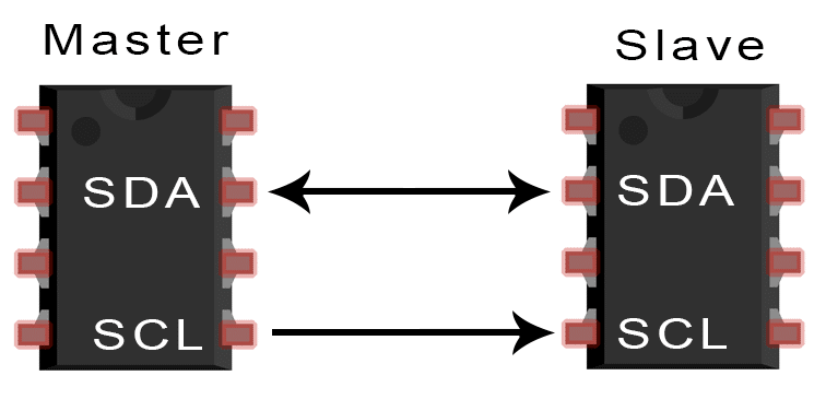
Like UART communication, I2C only uses two wires to transmit data between devices:
SDA (Serial Data) – The line for the master and slave to send and receive data.
SCL (Serial Clock) – The line that carries the clock signal.
I2C is a serial communication protocol, so data is transferred bit by bit along a single wire (the SDA line).
Like SPI, I2C is synchronous, so the output of bits is synchronized to the sampling of bits by a clock signal shared between the master and the slave. The clock signal is always controlled by the master.
With I2C, data is transferred in messages. Messages are broken up into frames of data. Each message has an address frame that contains the binary address of the slave, and one or more data frames that contain the data being transmitted. The message also includes start and stop conditions, read/write bits, and ACK/NACK bits between each data frame:
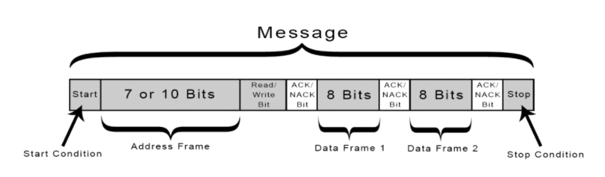
Start Condition: The SDA line switches from a high voltage level to a low voltage level before the SCL line switches from high to low.
Stop Condition: The SDA line switches from a low voltage level to a high voltage level after the SCL line switches from low to high.
Address Frame: A 7 or 10 bit sequence unique to each slave that identifies the slave when the master wants to talk to it.
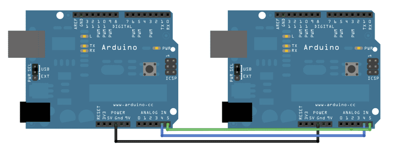
I started my test using two Arduinos. Connect pin A5 (the clock, or SCL, pin) and pin A4 (the data, or SDA, pin) on the master Arduino to their counterparts on the slave board. Make sure that both boards share a common ground. In order to enable serial communication, the slave Arduino must be connected to your computer via USB
below are the codes that I used for the test:
#include <Wire.h>

void setup()
{
  Wire.begin();   // join i2c bus
}
void loop ()
{
  Wire.beginTransmission(8);  //transmit to device number 8
  Wire.write('a');              //send one byte 00000000
  Wire.endTransmission();     //stop transmitting
  delay (500);

 Wire.beginTransmission(8);  //transmit to device number 8
 Wire.write('b');
 Wire.endTransmission();     //stop transmitting
 delay (500);
}#include <Wire.h>
void setup()
{
Wire.begin(8); // join i2c bus with address 8
Wire.onReceive(receiveEvent); //register event
Serial.begin(9600); //start serial communication
pinMode(13,OUTPUT);
}
byte x = 0;
void loop ()
{
delay(100);
}
//function that executes whenver data is received from master
//this function is registered as an event
void receiveEvent(int howMany){
while(Wire.available()){
char c = Wire.read();
Serial.println(c);
if (c == 'a')
{digitalWrite (13,HIGH);}
else if (c == 'b')
{digitalWrite (13,LOW);}
}
}This code turn on and off the LED.
After I make sure that the code is worked. I connect my atmega328 board to Arduino.
atmega328 as a master The senderArduino as a slave The ReceiverThe below video shows the results: