Compare the performance and development workflows for different microcontroller families please visit the group page to view the comparison.
Document the work (in a group or individually).
Read the datasheet for the microcontroller you are programming.
Program the board I did made to do something, with as many different programming languages and programming environments as possible.
Arduino IDE 1.8.10
Code::Blocks
Freematics Builder
XOD Arduino
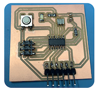
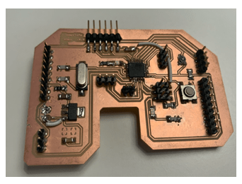
For this week’s assignment, I did use the ATtiny 44 Hello echo board and ATmega328P board designed and fabricated in Electronic Design week to programming them using different environments as possible.
First, we did recall some of the definitions we need understand to start programming, We had a local class with our instructor Hashim.
First of all, he did ask from us to download Code::Blocks and Freematics to start practicing before programme our own boards, these softwares are only available on Windows so I did use one of the laptops available in the lab as I’m a mac user.
The aim of the class was to programming Atmega328p microcontroller with Arduino IDE.
Here I mention some description of the programming environments used:
Code::Blocks : is a free, open source cross-platform IDE support several compilers such as C,C++, and Fortran.
Freematics Builder : Brings freedom to telematics projects involving OBD-II, GPS, MEMS sensor and wireless technologies based on open-source hardware.
As we are going to program ATmega328P which is 8-bit AVR RISC-based microcontroller, so we must have AVR ToolChains instilled in the laptop.
AVR GCC ToolChains is a collection of tools/libraries used to create applications for AVR microcontrollers.
This collection includes: compiler, assembler,linker, standard C ,and, math libraries.
Let us first understand how a program, using C compiler, is executed on a host machine:
| 1 | Human write (High level language) understandable such as C,C++ |
|---|
| 2 | Compiler | Generate assembly code (low level language) |
|---|
| 3 | Assembler | Converts the assembly language to (machine level language, 0’s and 1’s) |
|---|
| 4 | Linker | Tool used to link all the parts of the program together for execution (executable machine code) |
|---|
| 5 | Loader | loads all of them into memory and then the program is executed |
|---|
Makefile : is a tool to organize code for compilation.
For the input / output Ports and Pins we used three important register:
DDRx : Set input / output pins.
PORTx : Set value for output pins.
PINx : Reading input values.
Programming ATMEGA328P microcontroller with Arduino :
We need:
Code :: blocks
Freematics Builder
Arduino.
Arduino UNO Cable
Data sheet of the microcontroller used in Arduino, in my case it was Atmega328p.
We did program ATmega328P microcontroller using C language in Code:: Blocks and Freematics, we did these steps together in the class, but I forget to take a screenshot of the steps.
In short, we did start by opening code:: blocks and create a new project, then we must choose the AVR project and select processor of the project to be Atmega 328p, next we did run the code shown below, the aim of the code was to let the LED at the Arduino to blink:
#include <avr/io.h>
#include <util/delay.h>

int main(void)
{
    DDRB |= (1<<PB5); //setting PB5 as output
    // Insert code

    while(1)
    {
       PORTB |= (1<<PB5);// set PB5 high
       _delay_ms(1000);
       PORTB &= ~(1<<PB5);// set PB5 high
       _delay_ms(1000);
    }


}
Afterward, .hex will be created in the project file, we did open freematics and open the .hex file just formed and run it. The LED was blinking its was working perfectly.
Before all else, We need to start with setup the programmer and board type in Arduino IDE, as I going to use FabISP I fabricate in Electronic production week as programmer I need to prepare it for first time use.
First I did update Arduino IDE to the last available version which is 1.8.10.
Connect my board with FabISP through the ISP header using a ribbon connecter, and I need to make sure the laptop recognizes USBtinyISP.
Open Arduino IDE, download ATtiny 44 board, then selected Tools –> Borad –> Atting44 as shown in the image below
Next, select the used processor, port, and, clock.
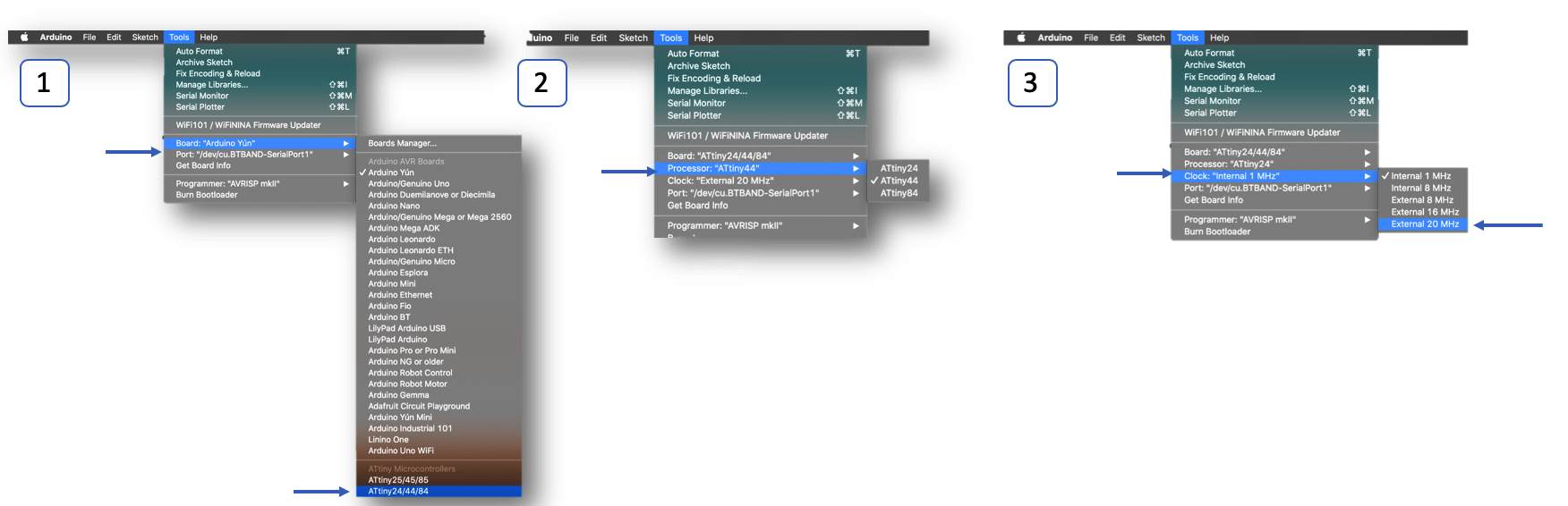
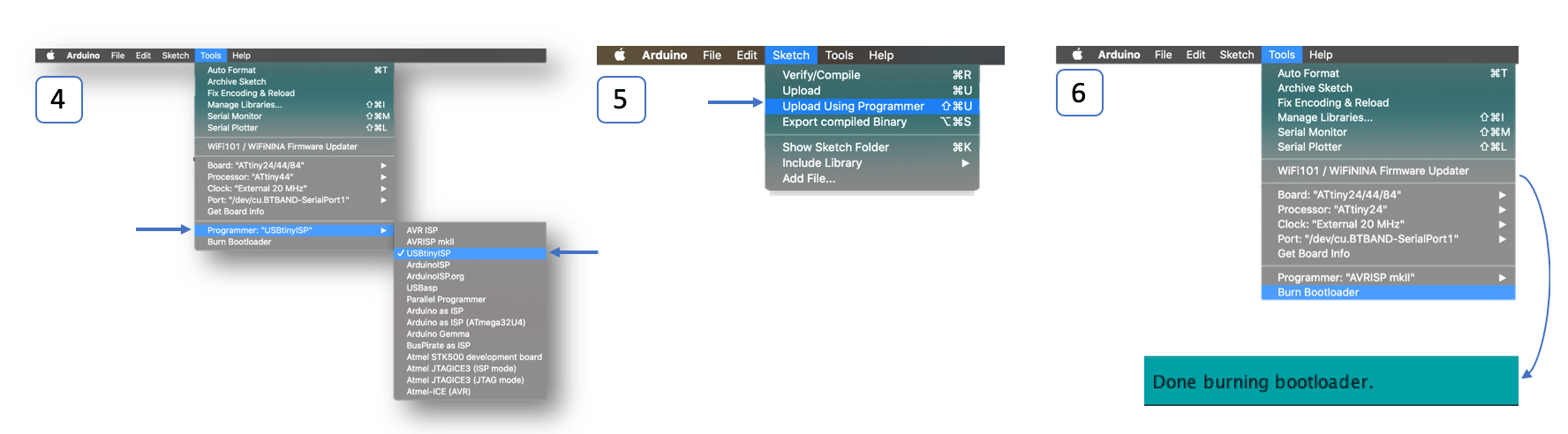
Select the programmer, then go to Sketch –> Upload using programmer
Go to Tools –> Burn Bootloader.
I did used more then one language using Arduino IDE environment:
C language.
Arduino language.
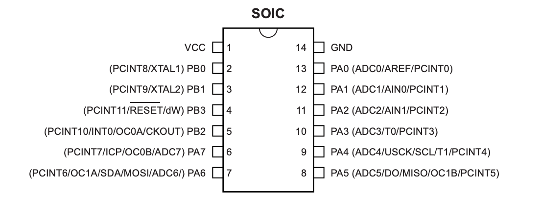
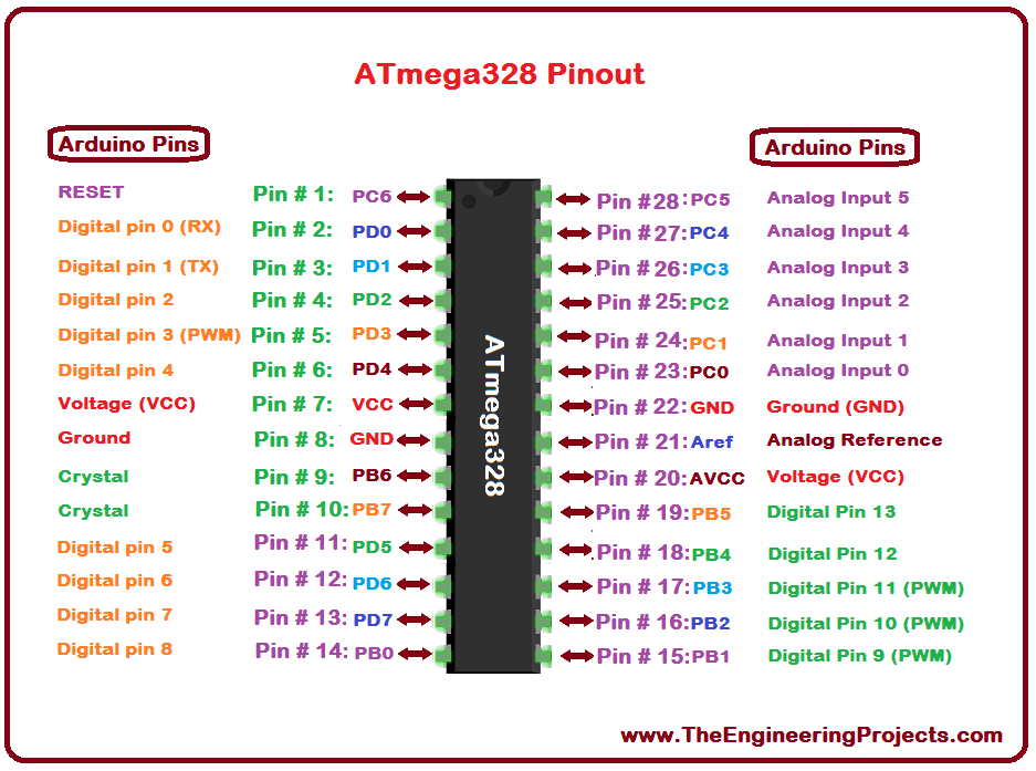
The aim of the code to make the LED ON whenever the button is pressed, I will need the datasheet of ATtiny 44 to see outputs and inputs pins to set them, reading and understanding datasheet for the microcontroller is very important to be able to write good code, the image below shows the pin configurations for ATtiny 44, also I did use the schematic of the board to know where to connect the inputs and outputs in my case the input is the button it’s was connected in port A, pin 7 –> PA7, on the other hand, the output LEDwas connected in PB2:
I did re-run the code that we wrote it together in the class, but I changed the pins to the corresponding pins on my board.
#include <avr/io.h>

int main(void) {


DDRB |= (1<<PB2);  //SET OUTPUT LED
DDRA &= ~(1<<PA7); // SET INPUT BOTTON
PORTA |= (1<<PA7);


while(1)

      {
if(PINA &(1<<PA7))
{
PORTB &=~ (1<<PB2);
}
else
{
PORTB |= (1<<PB2);

      }
      }
}
First I did declare the input and output using these commands the command below:
DDRB |= (1<<PB2)
DDRA &= ~(1<<PA7)
The below command used to write pin PA7 to high (1), which will activate the pull-up resistor.
PORTA |= (1<<PA7)
Then I did use while loop, the condition of the loop was (Always true):
while(1)
As shown the if statement inside the loop:
if(PINA &(1<<PA7))
{
PORTB &=~ (1<<PB2);
}
else
{
PORTB |= (1<<PB2);
first the condition PINA &(1<<PA7) will be check if PA7 is high or not.
if PA7 high –> PORTB &=~ (1<<PB2);
if PA7 low –>PORTB |= (1<<PB2);

  int const LED = 8; // the pin on my bored not in AtTiny 44
  int const BOTTON = 7;
  int botton_stat = 0;


void setup() {
  // put your setup code here, to run once:
pinMode(LED,OUTPUT);
pinMode(BOTTON,INPUT);
digitalWrite(BOTTON,HIGH);

}
void loop() {

botton_stat = digitalRead(BOTTON);

if (botton_stat == HIGH)
{
    digitalWrite(LED,LOW);   // turn the LED off by making the voltage LOW
}
else{
  digitalWrite(LED,HIGH);   // turn the LED on (HIGH is the voltage level)


}

}
For this time before I start writing the code I need to connect my board with fabISP and only to burn Bootloader, without uploading using programmer, Afterward, I can upload any code I want through FTDI cable.
I faced some problems while burning bootloader, And with the help of our instructor Hashim, we fixed them.
First I did a complete debugging for the board using a multimeter to check there is no short circuit, also the connection between the pins is good.
Everything was good on the board, so I did plug the fabISP into my board and select these settings shown below, I did click burn Bootloader. Unfortunately I get the error shown below which means I had a problem in my connections.
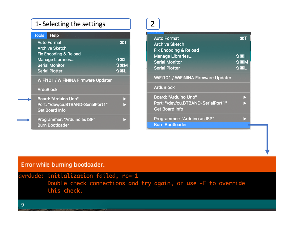
Since I did make sure there was no short circuit in my board, I have to refer to my layout design and check if I connected all pins in the correct places. consequently, we did figure that the RST pin in the ISP header wasn’t connected to the MCU at all ^^!
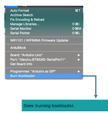
So I did some modifications to the board by adding external wire and connect the RST to the corresponding pin in the MCU Then I did repeat and tried to burn Bootloader and was done successfully, Now I can program my board as I want :).
XOD IDE or what known as Zod, it’s a free open-source visual programming environment that allows users to program an Arduino without writing any code, only by using blocks. To download the software click here.
To begin with, I did watch tutorial on Youtube to understand how to use it, programming in XOD is really easy and fun, we need only to drag the blocks and setting the inputs and outputs.
XOD is using visual objects called nodes which are small boxes with little circles on them these circles are called pins and they are used to connect between the nodes, the top pins in the nodes they are the inputs and the bottom pins are the outputs.
First, I did want to program my ATtiny 44, but it wasn’t working, then I did some search and figure that XOD environment doesn’t support the ATTiny series of processors. Luckily, I have another board with a suitable processor ATmega328 I can use it to examen this environment.
Next, to test if I can upload program to the board, I did drag the LED node, and set the pin as shown below :
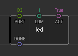
PORT: D3 –> Arduino pin connected to the LED.
LUM: 1 –> Set the LED ON
This code will keep the LED ON.
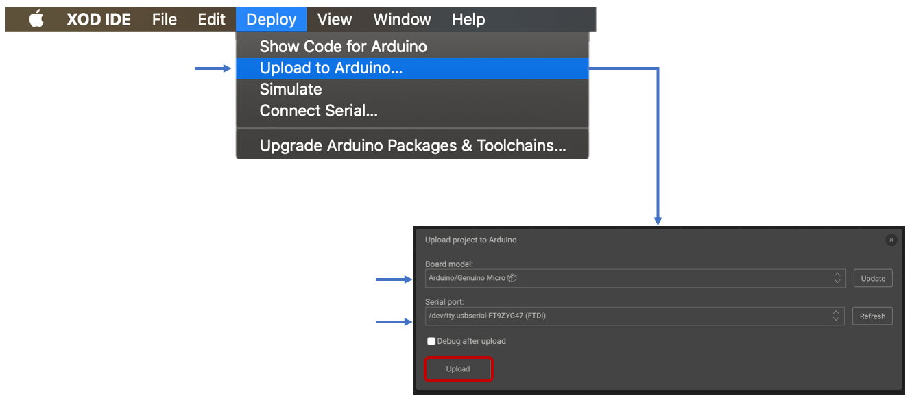
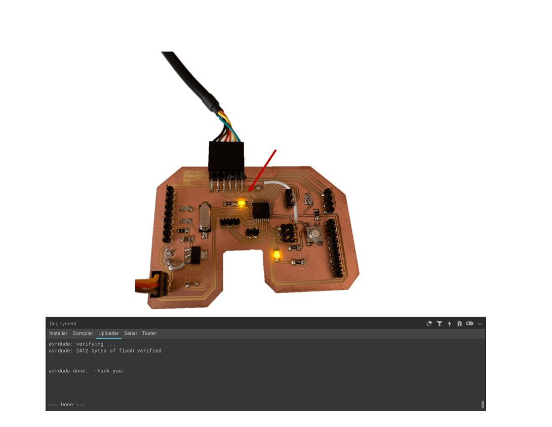
Go to Deploy –> Upload to Arduino, then a window will pop where I need to choose the correct board type and update if needed, also to make sure the board connected to the correct serial port, then I click into upload and the code was working aright as shown below:
The graphical representation below shows the code used to control the servo motor using the potentiometer, after uploading the code successfully.
I did use this video as a reference for the shown code below:
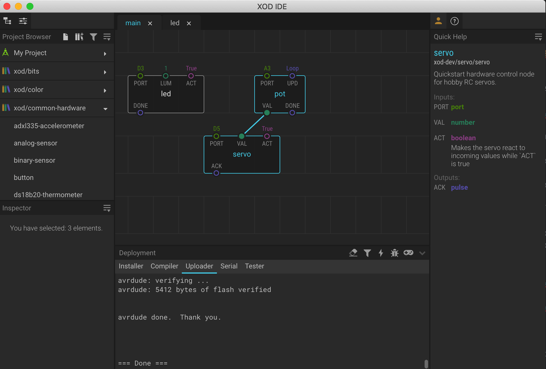
I will use a screw to rotate the potentiometer as the angle of rotation is changing the servo will work as shown in video below:
| File | Link |
|---|---|
| Blink code,ATtiny44 - (C language) ArdunioIDE | |
| Blink code - ATtiny44 - (Ardunio language) ArdunioIDE | |
| Control Servo & LED ON code- ATemga 328p - XOD IDE |
