
Please visit our group site to see the group assignment for this week.
Cut/Print sticker using Vinyl Cutter machine.
Design a parametric press fit construction kit and cut it using laser cutting machine.
corelDRAW.
Roland CutStudio
Autodesk Fusion.
Universal Laser System interface.
In this week the aim was to be familiar with all cutting machines available in the lab to be able to implement 2D and 3D designs.
First I did start by using Roland vinyl Cutter model CAMM-1 GS-24, I did choose to print the new UAE Nation Brand Logo.
Before start printing and upload the logo in the Computer I did adjust the machine by putting the sticker roll. I did use black color only, then the cutter will calculate the width of the sheet that I will need after in enter it in the software.
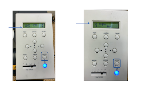
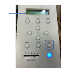
Moreover, I did test the force, I had found out the force give me the best cutting for the black sheet is 30gf, the testing was done by keep pressing test button in the cutter and it will cut for me a sample to see if used force good or not as shown in images below.
Afterward, I did open corelDRAW and follow the mention steps below:
Create new file.
Upload the logo in corelDRAW.
Right click in logo and choose " Quick Trace" this separates the image and create vector that I need it for printing.
Left click “no color box”, then Right click “Red color box” to display the traces .

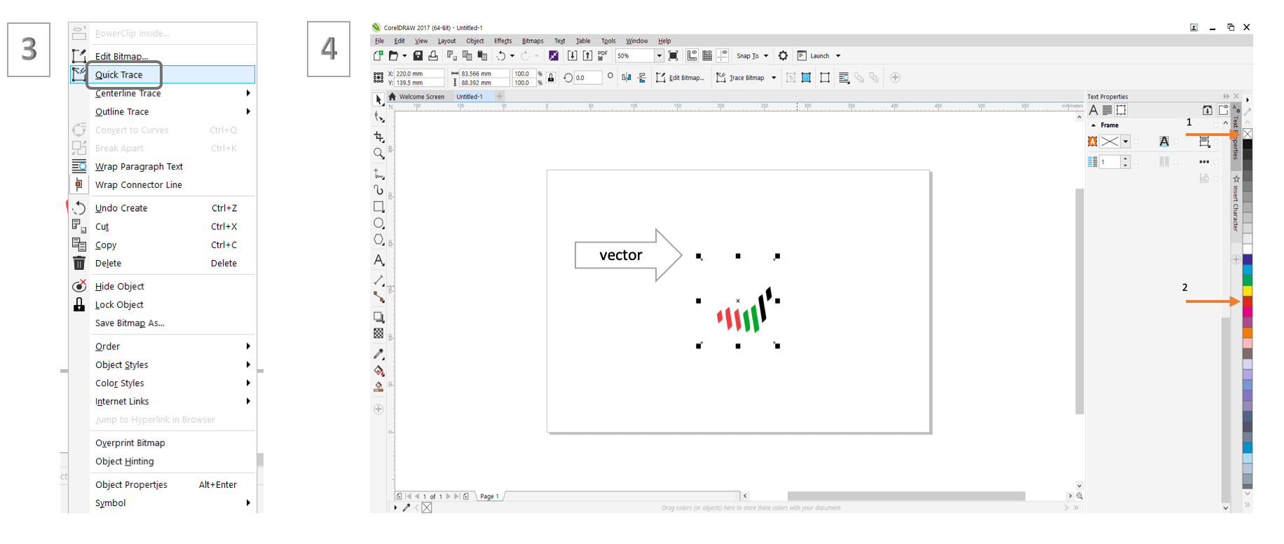
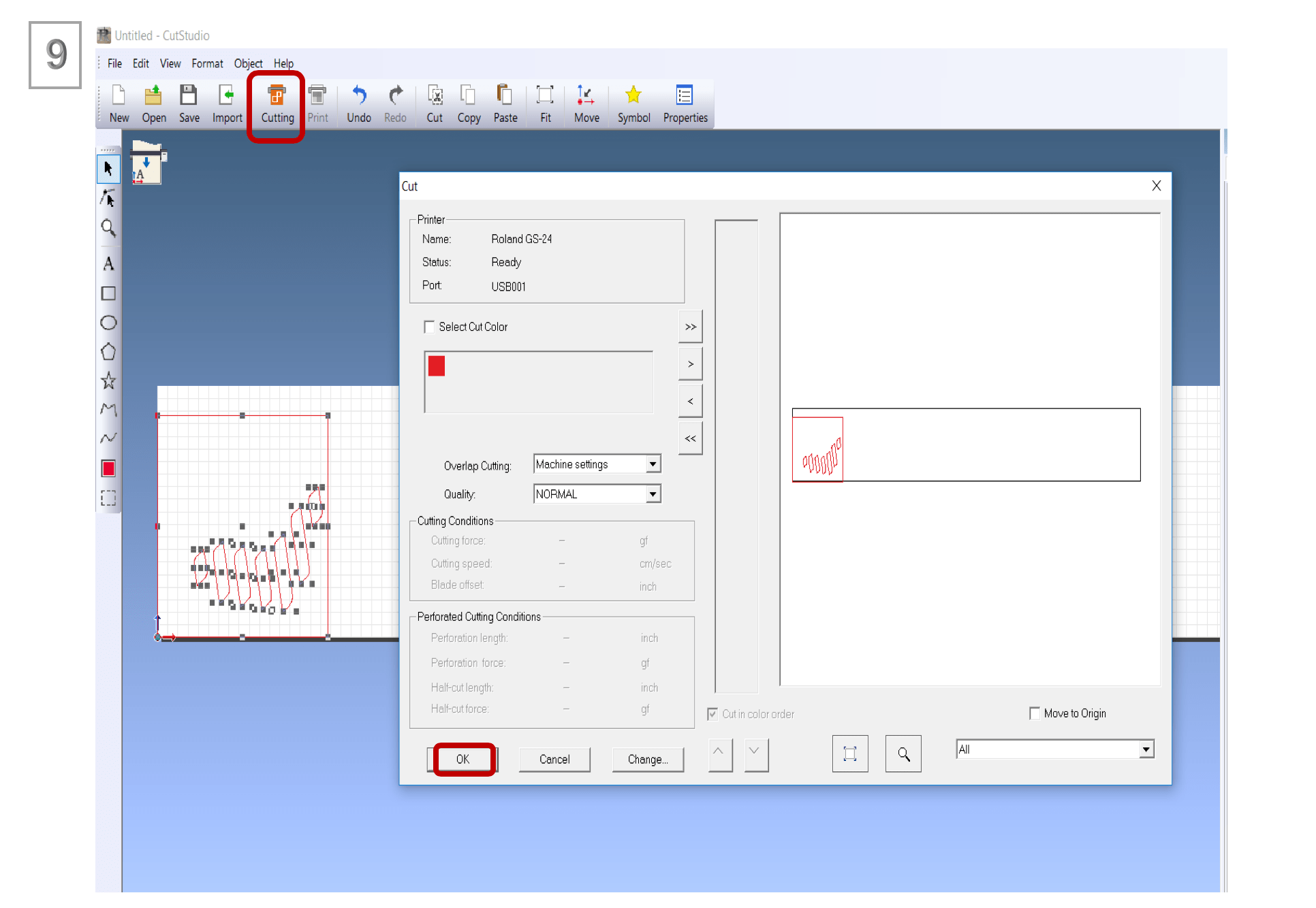
Press in the tool bar “Roland CutStudio” and select the traces want to cut and click update for the preview.
Press in the preview “Roland CutStudio” to send it the machine software.
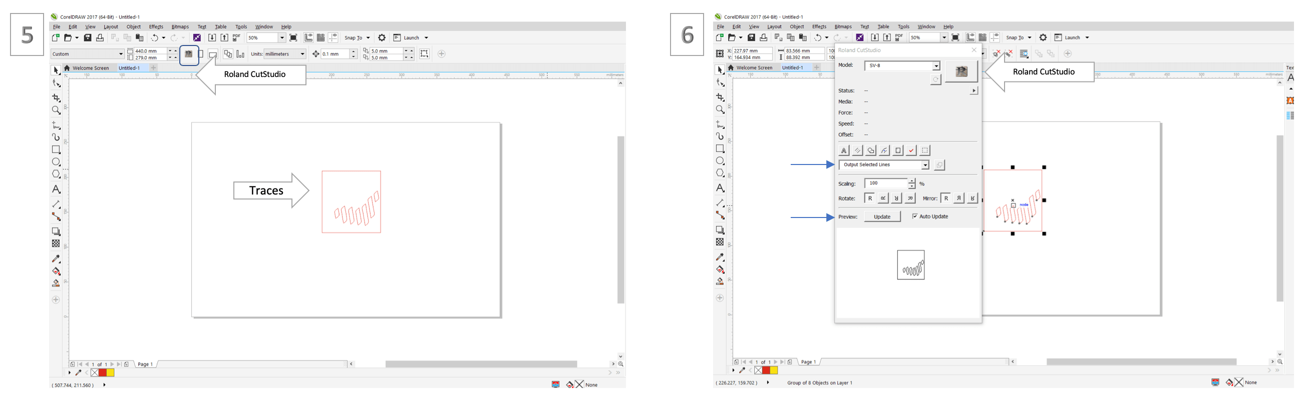
In Roland sowftware, select the logo and choose where to print in the sheet.
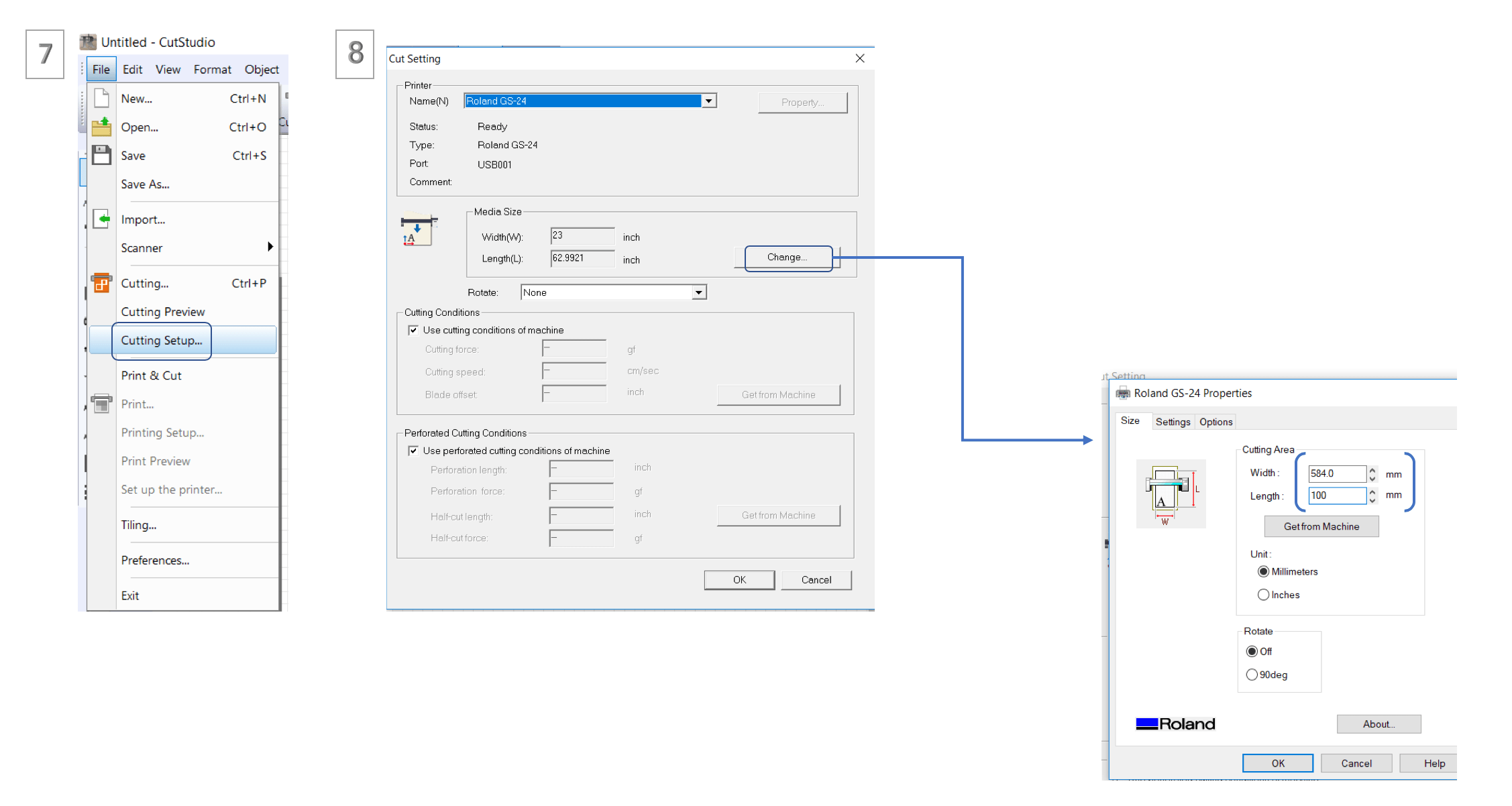
Then for adjusting size, I click file > cutting setup > size change > for the width I did enter the width calculated by the machine in my case was 584 m, for the length is depending on the design so I see the length of the logo in corelDRAW I put it 100 m.
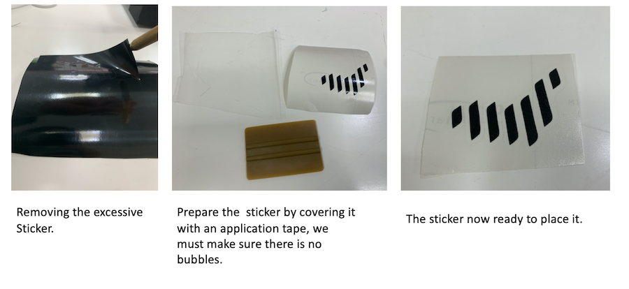
Now is the time to prepare the sticker as shown in the images below:
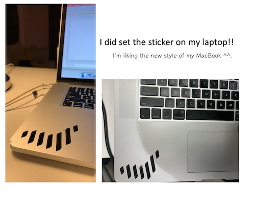
The final look of the sticker shown below:
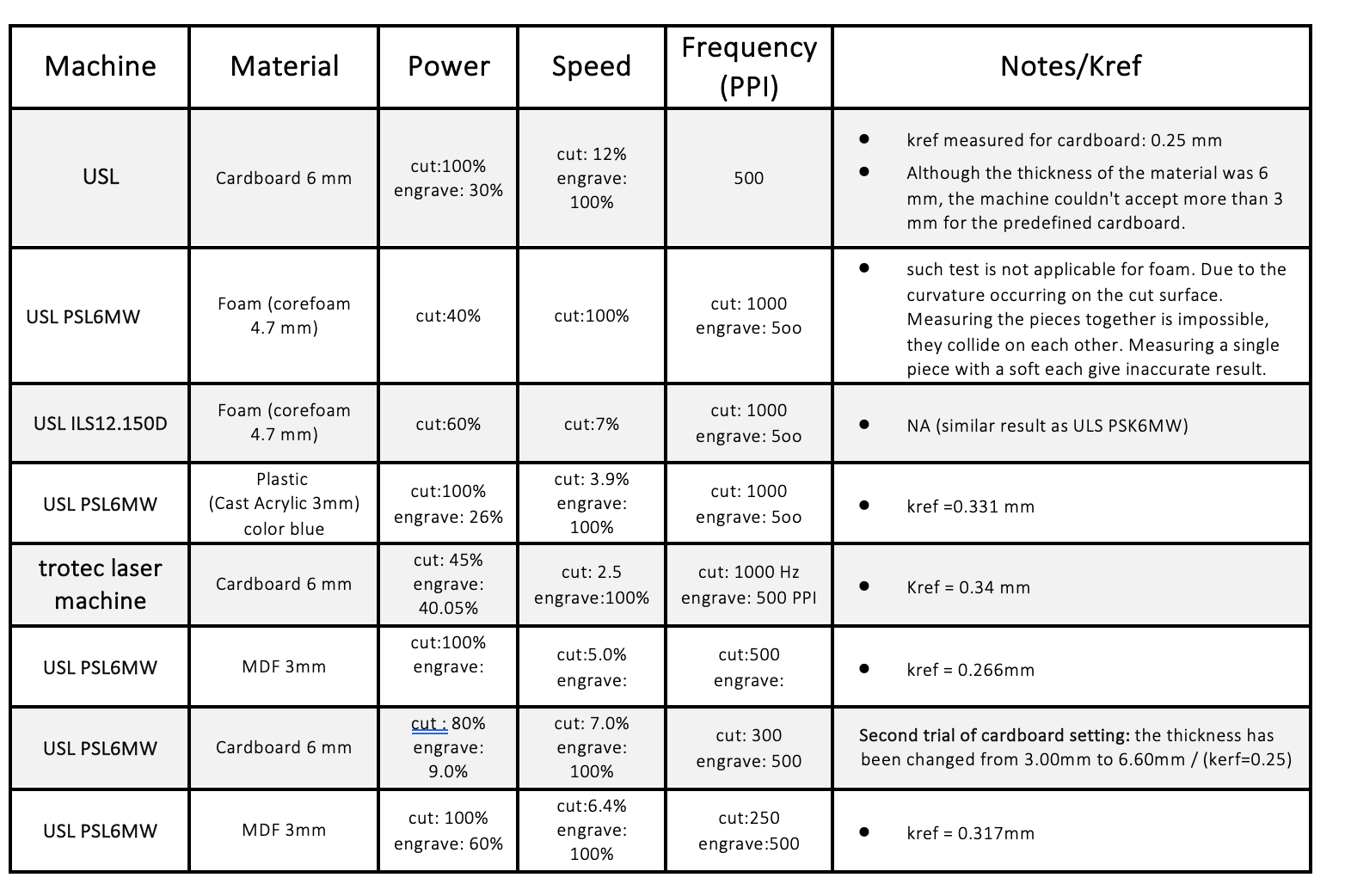
For the group assignment each student selected a material to identify there features for different laser cutter in the Lab there is three machines which are :
Universal Laser System ULS (PSL6MW).
Universal Laser System (ILS12.150D).
trotec laser machine.
We did share the setting of machines in Google Docs so we will be able to use this settings whenever we need the machines as shown below the table :
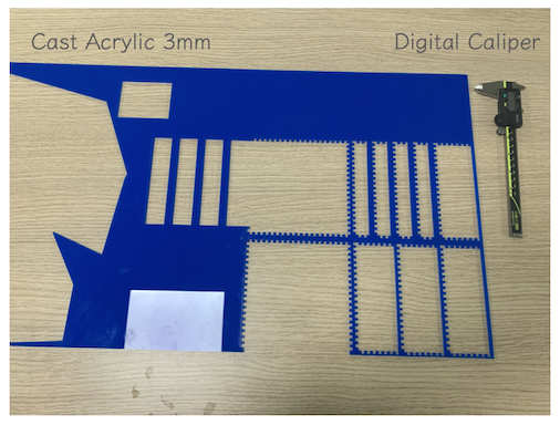
I did select: Plastic (Cast Acrylic 3mm) color blue, Of course I did use board already used to preserve materials.
There are two things we need to do to figure out the perfect cutting settings:
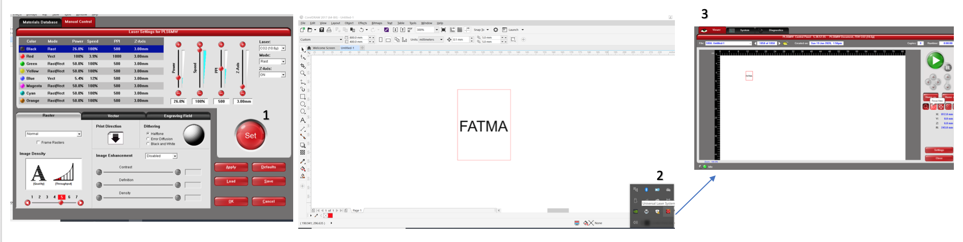
I have draw square to (test cutting) and write my name inside it to (test engraving) in corelDRAW. Moreover, for Universal Laser cutter PSL6MW) understand/used Red color for cutting and black color for engraving, so I have selected the square outline to be red to cut it, also I must select the line type to (hairline). In the other hand, for engraving I have select the name with black color.
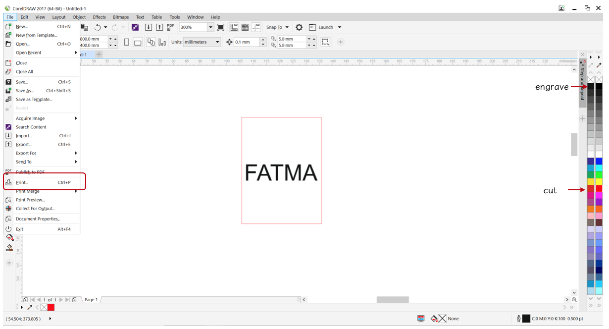
Next, click File >> Print >> Preferences >> Universal Laser systems control panel page will pop to add the setting needed for the machine.
Its important to add the right thickness of material otherwise we may having errors during cutting so we measure the the thickness using Digital Caliper from all the sides and then took the average, I found it equal to 3.152 mm.
Although, the material thickness is known from the manufacturer but still we need to measure it to avoid any possible error.
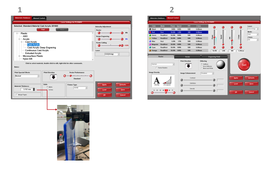
As shown above first for Material Database I select plastic >> Cast Acrylic, also I entered the material thickness 3.152 mm >> then press Apply.
(Failed )Manual control black color for engraving:
Power : 100%
Speed: 100%
PPI: 500
Manual control Red color for Cutting:
Power : 50%
Speed: 3.8%
PPI: 300
Perfect settings for (cutting and engrave) for Cast Actylic :
Manual control black color for engraving:
Power : 26%
Speed: 100%
PPI: 500
Manual control Red color for Cutting:
Power : 100%
Speed: 3.9%
PPI: 1000
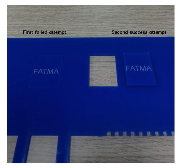
The above setting result the cutting and engraving shown below in the image it clear that the laser did not cut the board for the first attempt(failed), but the engrave was perfect so I did try one more time and I changed the material thickness to 3 mm and use the default setting for “Cast Actylic” and every thing went prefect for the cutting and engraving ,I had recode this settings in the table for future use.
The image below shown the laser cutting for the mention settings above :
After entering all value I press “set”, then I open Universal Laser System control panel from windows toolbar.
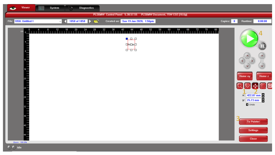
The focus in this machine is automatic, the autofocus depends on the material type and thickness, the program afterward will do the work of calculating the focus. Then choose the “focus view” icon, next, move the design to the place want it to be printed by using “Relocated View” then press " To Pointer" to put the design in place I choose then press play button to start cutting.
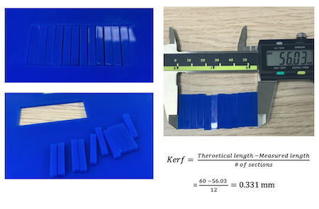
Kerf is the width of material that is removed by a cutting process. For the kerf calculation, Shaikha did create rectangular (60x25 mm) and section it to 12 equal parts we can have more sections, increasing the sections number will make the calculation more accurate, all of us used the same file to insure having uniform dimensions. Afterward, we used Digital Caliper to measure the length after cutting in order to find the kerf.
In begin I decided to build " house " consist of cube and pyramid. However, it took from me a lot of time. Thus I decided to try it at another time to be able finish the assignment for this week, also to not waste more material, also i do forget that the design of the press fit kit must be parametric and can be assembled from all the directions so designing house will not work for this assignment anyway.
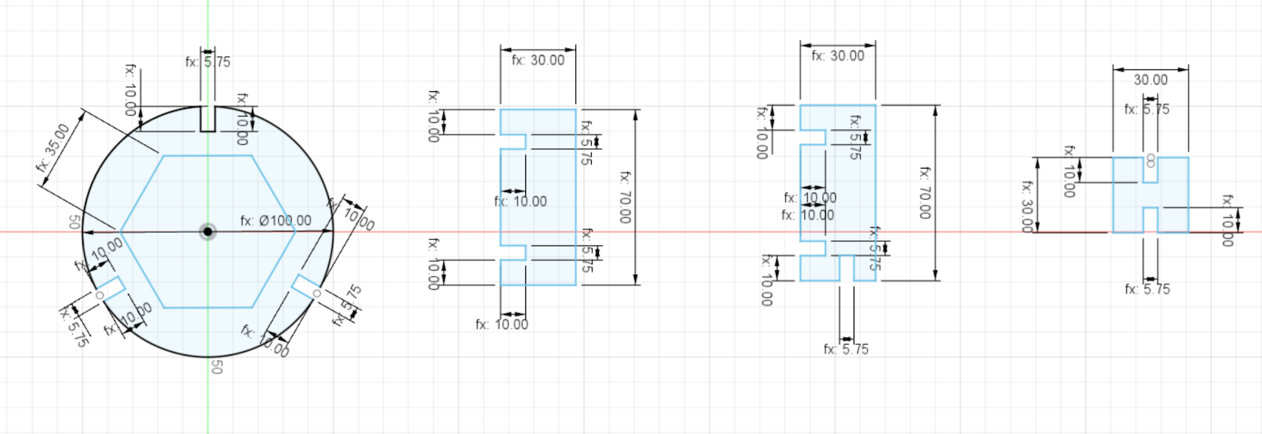
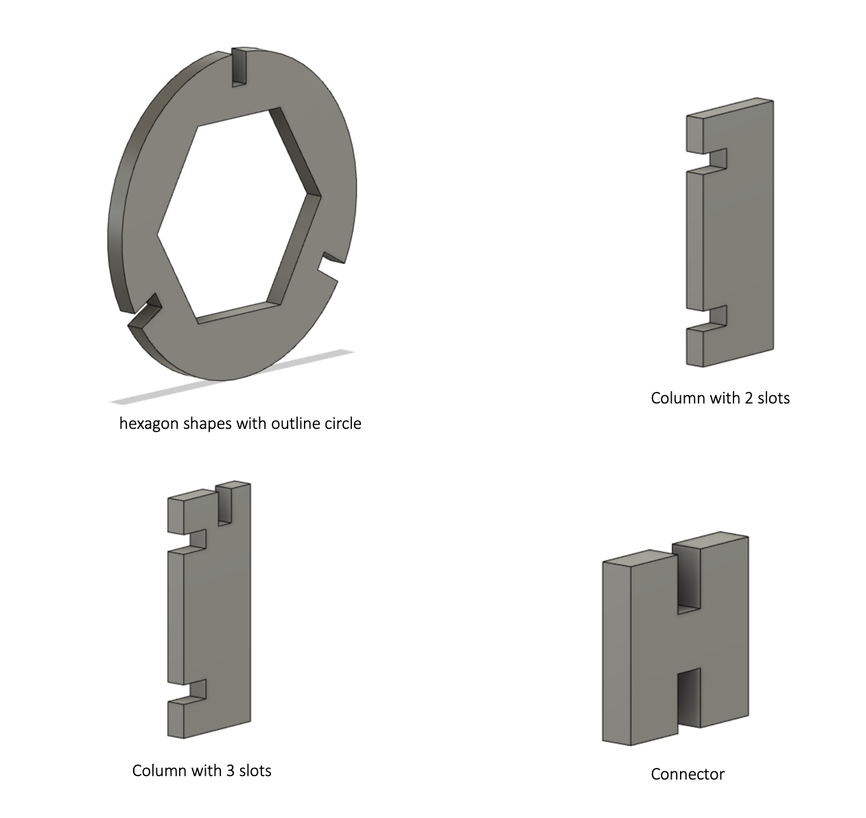
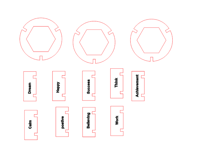
My press fi kit design consist of outline circle inside it hexagon shape with 3 slots, and 3 columns and connectors using Fusion. The behind idea my structure to display the importance and element of team work.
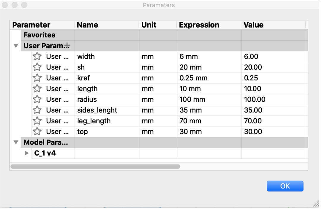
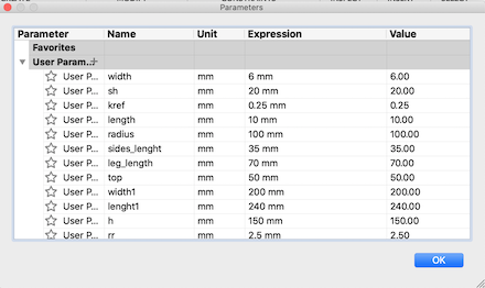
I did set the dimension parameters in order to have a parametric design as shown below:
Then press Finish sketch to save the file in formate understandable by corelDRAW which I need to use it after with the Universal Laser System. After that, Right click on sketch save as DXF.
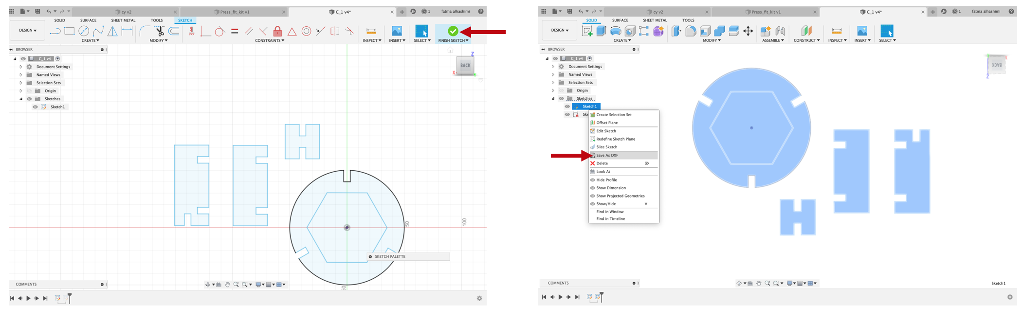
Then open the file corelDRAW in computer connected to the laser cutter.I did some edits before printing I did write words in the columns engrave it.
Used material in this task was “Cardboard” which not expensive and easy to find.
Used machine was "Universal Laser systems PLS6MW, I did used the cutting setting obtained in the group task for more details see my colleague Maha documentation since she did the setting for this material.
Manual control black color for engraving:
Power : 90%
Speed: 10%
PPI: 500
Manual control Red color for Cutting:
Power : 80%
Speed: 7.0%
PPI: 300
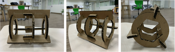
After printing and starting to set up my Kit I figure out that I need connectors to have the third layer
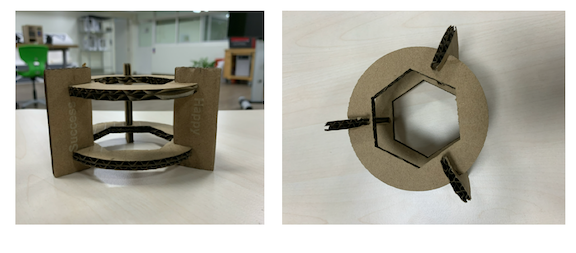
so I did some modifications in the column and add slot to fit the connectors in them.
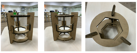
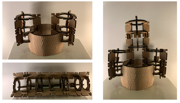
The image below shows my final press fit kit from different sides View:
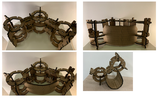
To improve my press-fit kit I did some modifications for it by adding flexible parts, our instructor Hashim advised me to add 2 parts of my small bridge and try to connect them by the flexible part, this technique will let me build different towers.
I improved my sketch to solve the issue with the previous design, as shown in the Fusion sketch below, one of the main modifications that I created is adding fillets in my design that the parts can be attached to each other easily and I did add more slots to add more layers :

Well this idea open my mind for a lot of structure can be made with my press fit as shown below:
| File | Link |
|---|---|
| Press Fit Kit - Autoesk Fusion 360(file.f3d) | |
| Flexible part - Autoesk Fusion 360(file.f3d) | |
| coralDraw | |
| The Emirates Nation Brand Logo |
