
| Processing | Blynk |
|---|---|
|
|
To start this week we had an online local class, about Processing software and how to use it with Arduino IDE.
Processing is a sketchbook software, allows us to code using visual context. I followed this tutorial done by SparkFun about processing to learn more about it, as we were asked by our instructor to follow it to be more familiar with the software.
Next, I started applying what I learned, and due to the lack of the components as we are working from home. the output device I selected was LED, as I don’t have a lot of options.
I will build a user interface that controls LEDs using buttons, Moreover, I will use the ATmega 328p board I fabricated in Electronic Design week.
For my final project, I will need a user interface loaded in the screen that attached into the robot, therefore, when the visitor enters the lab they can select the room they want, here in this example lets assume the LED is the location (position) they want to reach, and by clicking the button they select the desired location.
For the code reference visit the link, and to deal with different objects in the used library I used this link.
void setup() {

  pinMode(7, OUTPUT);   //set pin as output , blue led pd7 pin 7
  pinMode(8, OUTPUT);   //set pin as output , red led pb0 pin 8


  Serial.begin(9600);    //start serial communication @9600 bps
  }

void loop(){

  if(Serial.available()){  //id data is available to read

    char val = Serial.read();

    if(val == 'r'){       //if r received
      digitalWrite(7, HIGH); //turn on red led
      }
    if(val == 'b'){       //if b received
      digitalWrite(8, HIGH); //turn on blue led
      }


    if(val == 'f'){       //if f received
      digitalWrite(7, LOW); //turn off all led
      digitalWrite(8, LOW);
      }
    }
  }
import controlP5.*; //import ControlP5 library
import processing.serial.*;

Serial port;

ControlP5 cp5; //create ControlP5 object
PFont font;

void setup(){

  size(500, 300);    //window size, (width, height)

 // printArray(Serial.list());
  port = new Serial(this, "/dev/tty.usbserial-FT9ZYG47", 9600);

  //lets add buton to empty window

  cp5 = new ControlP5(this);
  font = createFont("calibri light bold", 20);

  cp5.addButton("Lab")     //
    .setPosition(100, 50)  //x and y coordinates of upper left corner of button
    .setSize(120, 70)      //(width, height)
    .setFont(font)
  ;

  cp5.addButton("Workshop") //
     .setPosition(250, 50)  //x and y coordinates of upper left corner of button
    .setSize(120, 70)      //(width, height)
    .setFont(font)
  ;


  cp5.addToggle("goBack")
     .setPosition(100, 150)  //x and y coordinates of upper left corner of button
     .setSize(120, 20)      //(width, height)
     .setFont(font)
     ;


}

void draw(){

  background(150, 150, 150); // background color of window (r, g, b) or (0 to 255)

  //lets give title to our window
  fill(0, 0, 150);               //text color (r, g, b)
  textFont(font);
  text("Welcome to UAE fab lab", 130, 30);  // ("text", x coordinate, y coordinat)
}

//lets add some functions to our buttons
//so whe you press any button, it sends perticular char over serial port

void Lab(){ //this function will activates if you click on the "On" button
    port.write('r');

 }

void Workshop(){
  port.write('b');
}
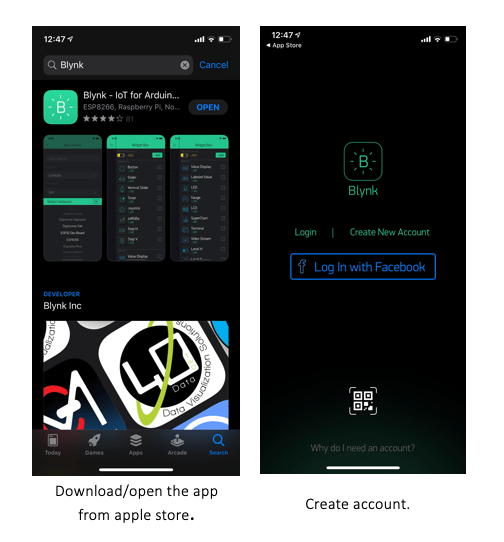
Blynk is IoT platform mobile app builder used to control Arduino and other microcontrollers with smartphones.
To work with Blynk I need:
A Smartphone.
IoT Hardware.
Internet Connection.
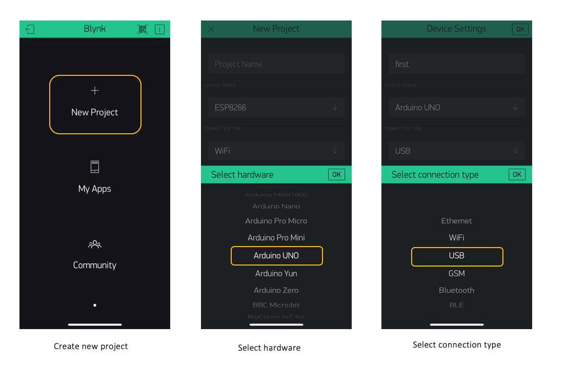
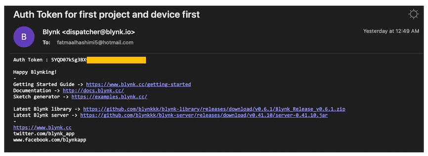
For every project in Blynk, it has a unique Token, I received an e-mail with an Auth Token.
I did build a user interface with button, to control the LED on my board.
First, in the app, I did add a terminal to my project so I can communicate with my board and it’s used to display data from the hardware and allows us to send strings to the hardware, then I added the button as shown below the selected settings:
Terminal Settings –> Select pin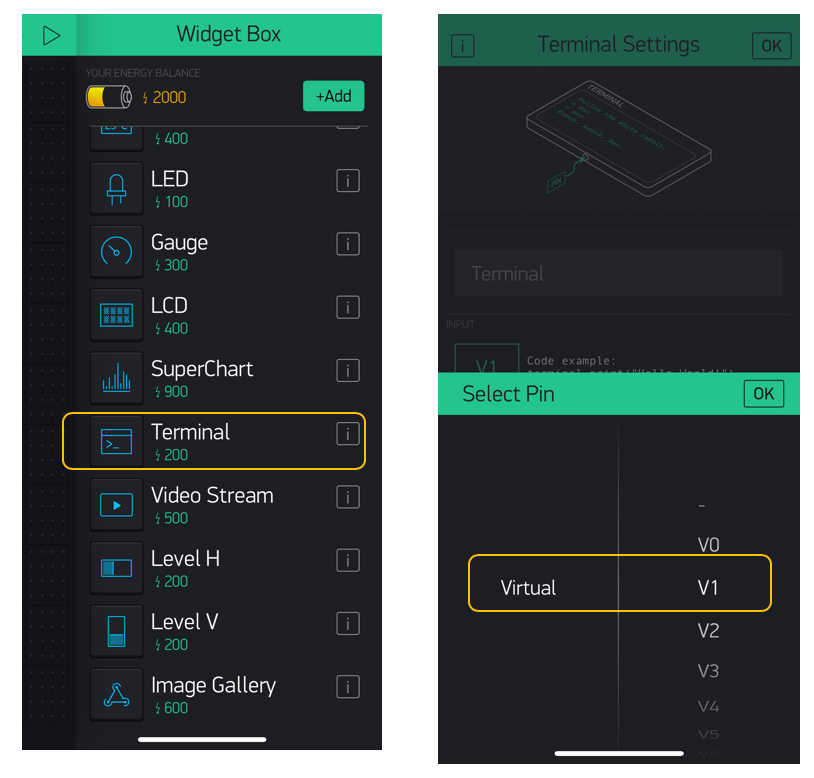
Styled button –> Select pin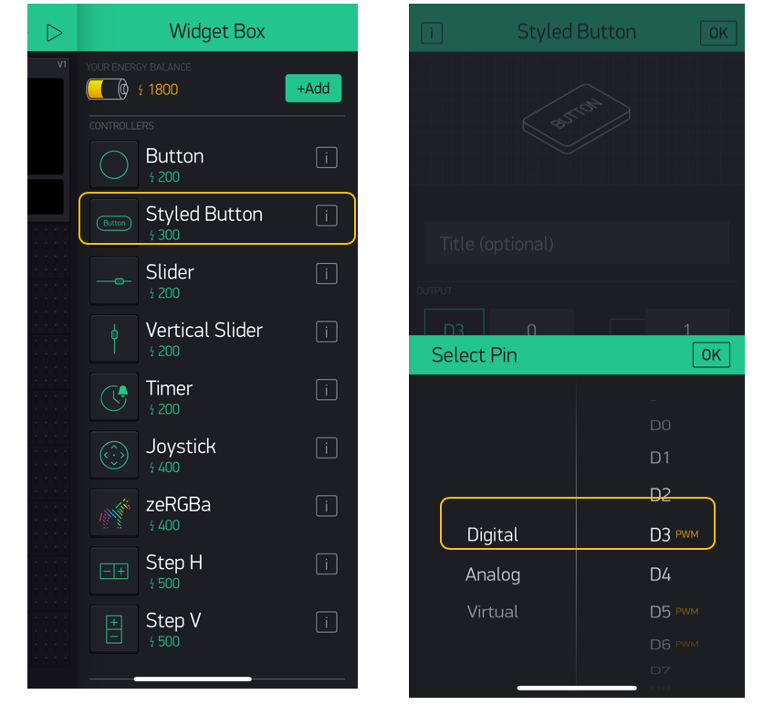
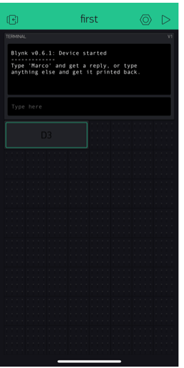
The screenshot below shows the project page, that named it “first”:
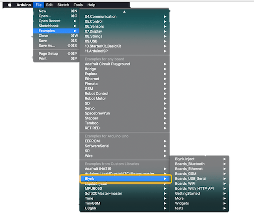
/*************************************************************
Download latest Blynk library here:
https://github.com/blynkkk/blynk-library/releases/latest
Blynk is a platform with iOS and Android apps to control
Arduino, Raspberry Pi and the likes over the Internet.
You can easily build graphic interfaces for all your
projects by simply dragging and dropping widgets.
Downloads, docs, tutorials: http://www.blynk.cc
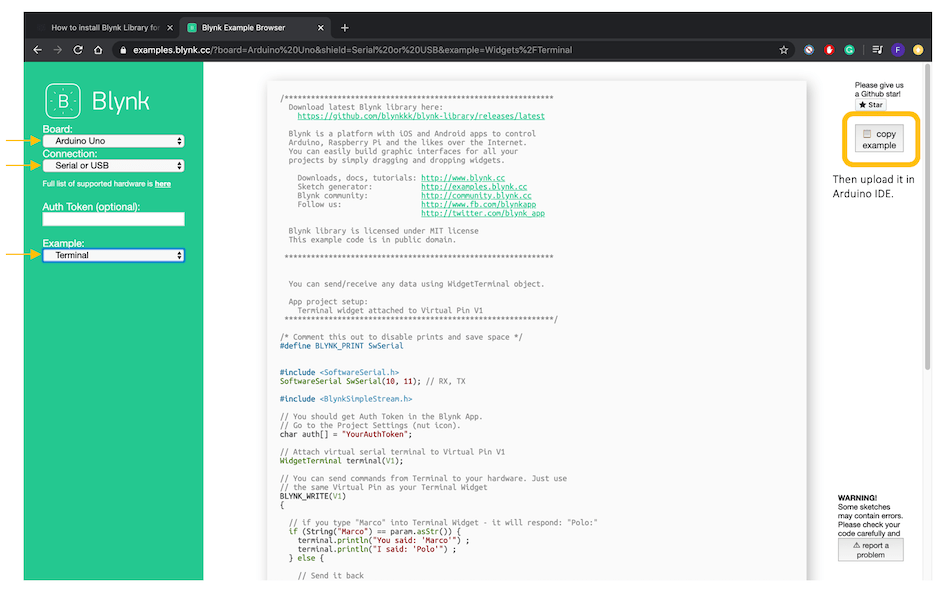
Sketch generator: http://examples.blynk.cc
Blynk community: http://community.blynk.cc
Follow us: http://www.fb.com/blynkapp
http://twitter.com/blynk_app
Blynk library is licensed under MIT license
This example code is in public domain.
*************************************************************
You can send/receive any data using WidgetTerminal object.
App project setup:
Terminal widget attached to Virtual Pin V1
*************************************************************/
/* Comment this out to disable prints and save space */
#define BLYNK_PRINT SwSerial
#include <SoftwareSerial.h>
SoftwareSerial SwSerial(10, 11); // RX, TX
#include <BlynkSimpleStream.h>
// You should get Auth Token in the Blynk App.
// Go to the Project Settings (nut icon).
char auth[] = "Token";
// Attach virtual serial terminal to Virtual Pin V1
WidgetTerminal terminal(V1);
// You can send commands from Terminal to your hardware. Just use
// the same Virtual Pin as your Terminal Widget
BLYNK_WRITE(V1)
{
// if you type "Marco" into Terminal Widget - it will respond: "Polo:"
if (String("Marco") == param.asStr()) {
terminal.println("You said: 'Marco'") ;
terminal.println("I said: 'Polo'") ;
} else {
// Send it back
terminal.print("You said:");
terminal.write(param.getBuffer(), param.getLength());
terminal.println();
}
// Ensure everything is sent
terminal.flush();
}
void setup()
{
// Debug console
SwSerial.begin(9600);
// Blynk will work through Serial
// Do not read or write this serial manually in your sketch
Serial.begin(9600);
Blynk.begin(Serial, auth);
// Clear the terminal content
terminal.clear();
// This will print Blynk Software version to the Terminal Widget when
// your hardware gets connected to Blynk Server
terminal.println(F("Blynk v" BLYNK_VERSION ": Device started"));
terminal.println(F("-------------"));
terminal.println(F("Type 'Marco' and get a reply, or type"));
terminal.println(F("anything else and get it printed back."));
terminal.flush();
}
void loop()
{
Blynk.run();
}
Then, I need to copy the Auth Token into the code, also I need to ensure that Virtual pin V1 is written in the code as I selected in the app project to be connected.
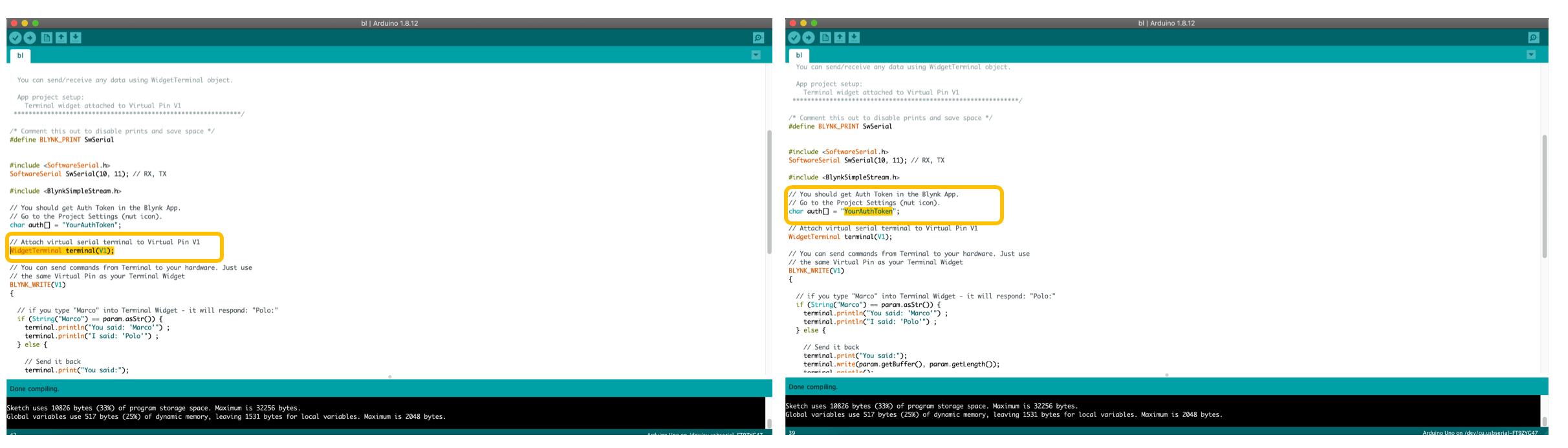
Next, Verify and Upload the code.
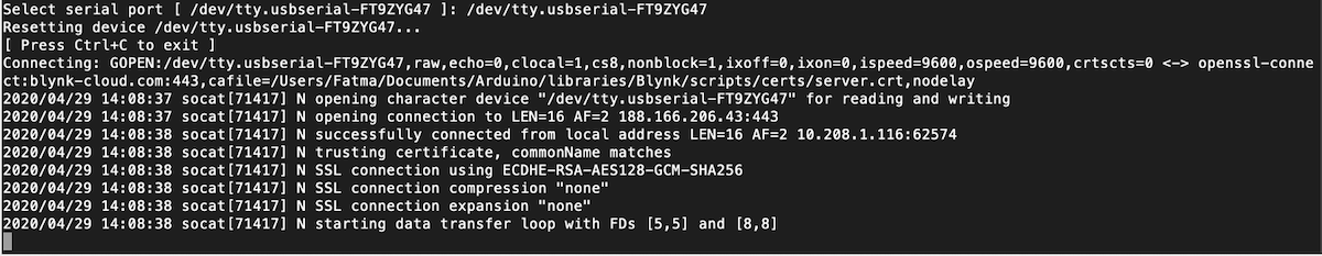
The device Authentication Token is used to connect my board with the Blynk cloud. the last step is to make the online connection:
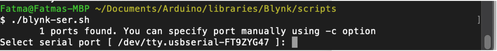
Open terminal
Go to the folder where Blynk library is saved.
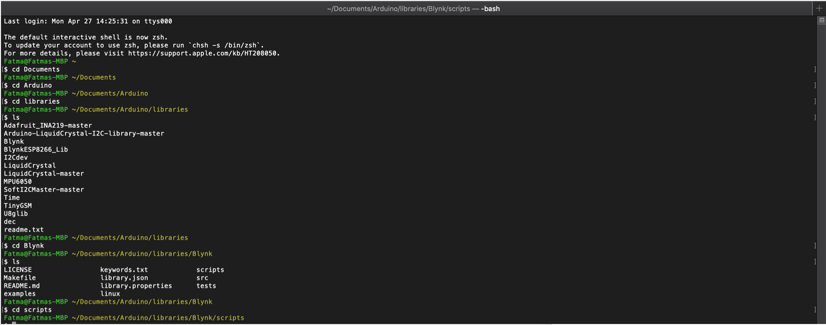
./blynk-ser.sh