Probe an input device(s)’s analog and digital signals.
Document the work (in a group or individually).
Now, we did reach the second half of the Fab Academy, where we are going from on to build on the previous weeks, using the techniques had learned to integrate them into my final project proposal. 01/04/2020
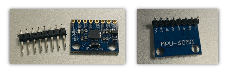
First of all, I decided this week to test MPU 6050 sensor as I may use it in my final project, although the sensor didn’t work with me, I would like to document my experience and describe the debugging I tried.
To begin with, I did watch and read some tutorials about MPU-6050.
MPU - 6050 is IMU (Inertial measurement unit) sensor , IMU sensors usually consists of 2 or more parts :
Accelerometer
Gyroscope
Magnetometer.
Altimeter.
MPU 6050 is 6 DOF ( Degrees of freedom) which it can give or measure 6 values as output, 3 values for Accelerometer and other 3 values for Gyroscope and both of them are embedded in a single chip use I2C protocol for commutation.
There is a lot of applications using MPU 6050, usually in robotics applications, here some examples:
Drones.
Robotic arm controls.
Self-balance.
Smartphones.
Games.
Moreover, I came to the conclusion that the sensor having a manufacturing defect. I’m planing when the lab is open to try another MPU-6050 sensor, to make sure the problem is in the hardware of the module or not.
I did mention below all the steps I did to reach this conclusion:
ATmega328P board I made in electronic design week, for the connection already I added headers in the board so I can connect MPU 6050 direct to the board, but unfortunately, I reversed the pins places between SCL and SDA by mistake, so I cant connected direct, I need to use a breadboard, Which I don’t like to use because some times the wire get out easily from the board and the connections not always reliable.MPU-6050 using the I2C commutation protocol, which means I need only to wires SCL and SDA.
SCL (Serial clock): Synchronize data transfer between the devices on the I2C bus and it’s generated by the master device in my case it’s ATmega328P board.
SDA (Serial Data): which carries the data.
The SCL and SDA pins correspond to special pins I can’t connect them to any inputs in the chip, In ATmega328 I must connect them to pin PC4 and PC5 respectively.
The image below shows the connections:
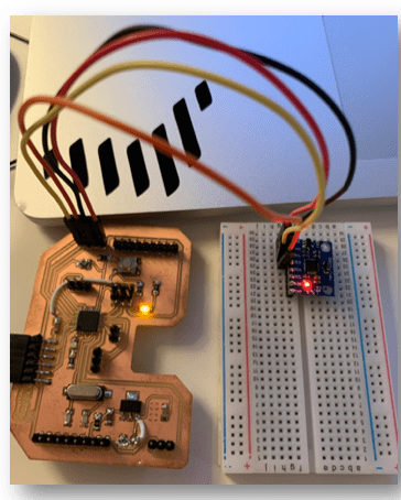
My board is similar to Arduino UNO as they have the same microcontroller chip, So I do use the below connection diagram as a reference for my commutation.

The libraries we are going to be using in our demo are part of the collection of libraries developed by Jeff Rowberg for working with the I2C bus and some common I2C sensors. You can find the complete set of libraries on Github.
These libraries are part of the collection of libraries developed by Jeff Rowberg for working with the I2C bus and some common I2C sensors:
I2C development library.
MPU-6050 library.
I Added the libraries.
Connected the board to the laptop.
Selected the board and port
I uploaded ready made code from: File –> Examples –> MPU6050 –> MPU6050_DMP6
// I2C device class (I2Cdev) demonstration Arduino sketch for MPU6050 class using DMP (MotionApps v2.0)
// 6/21/2012 by Jeff Rowberg <jeff@rowberg.net>
// Updates should (hopefully) always be available at https://github.com/jrowberg/i2cdevlib
//
// Changelog:
//      2013-05-08 - added seamless Fastwire support
//                 - added note about gyro calibration
//      2012-06-21 - added note about Arduino 1.0.1 + Leonardo compatibility error
//      2012-06-20 - improved FIFO overflow handling and simplified read process
//      2012-06-19 - completely rearranged DMP initialization code and simplification
//      2012-06-13 - pull gyro and accel data from FIFO packet instead of reading directly
//      2012-06-09 - fix broken FIFO read sequence and change interrupt detection to RISING
//      2012-06-05 - add gravity-compensated initial reference frame acceleration output
//                 - add 3D math helper file to DMP6 example sketch
//                 - add Euler output and Yaw/Pitch/Roll output formats
//      2012-06-04 - remove accel offset clearing for better results (thanks Sungon Lee)
//      2012-06-01 - fixed gyro sensitivity to be 2000 deg/sec instead of 250
//      2012-05-30 - basic DMP initialization working

/* ============================================
I2Cdev device library code is placed under the MIT license
Copyright (c) 2012 Jeff Rowberg

Permission is hereby granted, free of charge, to any person obtaining a copy
of this software and associated documentation files (the "Software"), to deal
in the Software without restriction, including without limitation the rights
to use, copy, modify, merge, publish, distribute, sublicense, and/or sell
copies of the Software, and to permit persons to whom the Software is
furnished to do so, subject to the following conditions:

The above copyright notice and this permission notice shall be included in
all copies or substantial portions of the Software.

THE SOFTWARE IS PROVIDED "AS IS", WITHOUT WARRANTY OF ANY KIND, EXPRESS OR
IMPLIED, INCLUDING BUT NOT LIMITED TO THE WARRANTIES OF MERCHANTABILITY,
FITNESS FOR A PARTICULAR PURPOSE AND NONINFRINGEMENT. IN NO EVENT SHALL THE
AUTHORS OR COPYRIGHT HOLDERS BE LIABLE FOR ANY CLAIM, DAMAGES OR OTHER
LIABILITY, WHETHER IN AN ACTION OF CONTRACT, TORT OR OTHERWISE, ARISING FROM,
OUT OF OR IN CONNECTION WITH THE SOFTWARE OR THE USE OR OTHER DEALINGS IN
THE SOFTWARE.
===============================================
*/

// I2Cdev and MPU6050 must be installed as libraries, or else the .cpp/.h files
// for both classes must be in the include path of your project
#include "I2Cdev.h"

#include "MPU6050_6Axis_MotionApps20.h"
//#include "MPU6050.h" // not necessary if using MotionApps include file

// Arduino Wire library is required if I2Cdev I2CDEV_ARDUINO_WIRE implementation
// is used in I2Cdev.h
#if I2CDEV_IMPLEMENTATION == I2CDEV_ARDUINO_WIRE
    #include "Wire.h"
#endif

// class default I2C address is 0x68
// specific I2C addresses may be passed as a parameter here
// AD0 low = 0x68 (default for SparkFun breakout and InvenSense evaluation board)
// AD0 high = 0x69
MPU6050 mpu;
//MPU6050 mpu(0x69); // <-- use for AD0 high

/* =========================================================================
   NOTE: In addition to connection 3.3v, GND, SDA, and SCL, this sketch
   depends on the MPU-6050's INT pin being connected to the Arduino's
   external interrupt #0 pin. On the Arduino Uno and Mega 2560, this is
   digital I/O pin 2.
 * ========================================================================= */

/* =========================================================================
   NOTE: Arduino v1.0.1 with the Leonardo board generates a compile error
   when using Serial.write(buf, len). The Teapot output uses this method.
   The solution requires a modification to the Arduino USBAPI.h file, which
   is fortunately simple, but annoying. This will be fixed in the next IDE
   release. For more info, see these links:

   http://arduino.cc/forum/index.php/topic,109987.0.html
   http://code.google.com/p/arduino/issues/detail?id=958
 * ========================================================================= */


// uncomment "OUTPUT_READABLE_QUATERNION" if you want to see the actual
// quaternion components in a [w, x, y, z] format (not best for parsing
// on a remote host such as Processing or something though)
//#define OUTPUT_READABLE_QUATERNION

// uncomment "OUTPUT_READABLE_EULER" if you want to see Euler angles
// (in degrees) calculated from the quaternions coming from the FIFO.
// Note that Euler angles suffer from gimbal lock (for more info, see
// http://en.wikipedia.org/wiki/Gimbal_lock)
//#define OUTPUT_READABLE_EULER

// uncomment "OUTPUT_READABLE_YAWPITCHROLL" if you want to see the yaw/
// pitch/roll angles (in degrees) calculated from the quaternions coming
// from the FIFO. Note this also requires gravity vector calculations.
// Also note that yaw/pitch/roll angles suffer from gimbal lock (for
// more info, see: http://en.wikipedia.org/wiki/Gimbal_lock)
#define OUTPUT_READABLE_YAWPITCHROLL

// uncomment "OUTPUT_READABLE_REALACCEL" if you want to see acceleration
// components with gravity removed. This acceleration reference frame is
// not compensated for orientation, so +X is always +X according to the
// sensor, just without the effects of gravity. If you want acceleration
// compensated for orientation, us OUTPUT_READABLE_WORLDACCEL instead.
//#define OUTPUT_READABLE_REALACCEL

// uncomment "OUTPUT_READABLE_WORLDACCEL" if you want to see acceleration
// components with gravity removed and adjusted for the world frame of
// reference (yaw is relative to initial orientation, since no magnetometer
// is present in this case). Could be quite handy in some cases.
//#define OUTPUT_READABLE_WORLDACCEL

// uncomment "OUTPUT_TEAPOT" if you want output that matches the
// format used for the InvenSense teapot demo
//#define OUTPUT_TEAPOT


#define LED_PIN 13 // (Arduino is 13, Teensy is 11, Teensy++ is 6)
bool blinkState = false;

// MPU control/status vars
bool dmpReady = false;  // set true if DMP init was successful
uint8_t mpuIntStatus;   // holds actual interrupt status byte from MPU
uint8_t devStatus;      // return status after each device operation (0 = success, !0 = error)
uint16_t packetSize;    // expected DMP packet size (default is 42 bytes)
uint16_t fifoCount;     // count of all bytes currently in FIFO
uint8_t fifoBuffer[64]; // FIFO storage buffer

// orientation/motion vars
Quaternion q;           // [w, x, y, z]         quaternion container
VectorInt16 aa;         // [x, y, z]            accel sensor measurements
VectorInt16 aaReal;     // [x, y, z]            gravity-free accel sensor measurements
VectorInt16 aaWorld;    // [x, y, z]            world-frame accel sensor measurements
VectorFloat gravity;    // [x, y, z]            gravity vector
float euler[3];         // [psi, theta, phi]    Euler angle container
float ypr[3];           // [yaw, pitch, roll]   yaw/pitch/roll container and gravity vector

// packet structure for InvenSense teapot demo
uint8_t teapotPacket[14] = { '$', 0x02, 0,0, 0,0, 0,0, 0,0, 0x00, 0x00, '\r', '\n' };


// ================================================================
// ===               INTERRUPT DETECTION ROUTINE                ===
// ================================================================

volatile bool mpuInterrupt = false;     // indicates whether MPU interrupt pin has gone high
void dmpDataReady() {
    mpuInterrupt = true;
}


// ================================================================
// ===                      INITIAL SETUP                       ===
// ================================================================

void setup() {
    // join I2C bus (I2Cdev library doesn't do this automatically)
    #if I2CDEV_IMPLEMENTATION == I2CDEV_ARDUINO_WIRE
        Wire.begin();
        TWBR = 24; // 400kHz I2C clock (200kHz if CPU is 8MHz)
    #elif I2CDEV_IMPLEMENTATION == I2CDEV_BUILTIN_FASTWIRE
        Fastwire::setup(400, true);
    #endif

    // initialize serial communication
    // (115200 chosen because it is required for Teapot Demo output, but it's
    // really up to you depending on your project)
    Serial.begin(115200);
    while (!Serial); // wait for Leonardo enumeration, others continue immediately

    // NOTE: 8MHz or slower host processors, like the Teensy @ 3.3v or Ardunio
    // Pro Mini running at 3.3v, cannot handle this baud rate reliably due to
    // the baud timing being too misaligned with processor ticks. You must use
    // 38400 or slower in these cases, or use some kind of external separate
    // crystal solution for the UART timer.

    // initialize device
    Serial.println(F("Initializing I2C devices..."));
    mpu.initialize();

    // verify connection
    Serial.println(F("Testing device connections..."));
    Serial.println(mpu.testConnection() ? F("MPU6050 connection successful") : F("MPU6050 connection failed"));

    // wait for ready
    Serial.println(F("\nSend any character to begin DMP programming and demo: "));
    while (Serial.available() && Serial.read()); // empty buffer
    while (!Serial.available());                 // wait for data
    while (Serial.available() && Serial.read()); // empty buffer again

    // load and configure the DMP
    Serial.println(F("Initializing DMP..."));
    devStatus = mpu.dmpInitialize();

    // supply your own gyro offsets here, scaled for min sensitivity
    mpu.setXGyroOffset(220);
    mpu.setYGyroOffset(76);
    mpu.setZGyroOffset(-85);
    mpu.setZAccelOffset(1788); // 1688 factory default for my test chip

    // make sure it worked (returns 0 if so)
    if (devStatus == 0) {
        // turn on the DMP, now that it's ready
        Serial.println(F("Enabling DMP..."));
        mpu.setDMPEnabled(true);

        // enable Arduino interrupt detection
        Serial.println(F("Enabling interrupt detection (Arduino external interrupt 0)..."));
        attachInterrupt(0, dmpDataReady, RISING);
        mpuIntStatus = mpu.getIntStatus();

        // set our DMP Ready flag so the main loop() function knows it's okay to use it
        Serial.println(F("DMP ready! Waiting for first interrupt..."));
        dmpReady = true;

        // get expected DMP packet size for later comparison
        packetSize = mpu.dmpGetFIFOPacketSize();
    } else {
        // ERROR!
        // 1 = initial memory load failed
        // 2 = DMP configuration updates failed
        // (if it's going to break, usually the code will be 1)
        Serial.print(F("DMP Initialization failed (code "));
        Serial.print(devStatus);
        Serial.println(F(")"));
    }

    // configure LED for output
    pinMode(LED_PIN, OUTPUT);
}


// ================================================================
// ===                    MAIN PROGRAM LOOP                     ===
// ================================================================

void loop() {
    // if programming failed, don't try to do anything
    if (!dmpReady) return;

    // wait for MPU interrupt or extra packet(s) available
    while (!mpuInterrupt && fifoCount < packetSize) {
        // other program behavior stuff here
        // .
        // .
        // .
        // if you are really paranoid you can frequently test in between other
        // stuff to see if mpuInterrupt is true, and if so, "break;" from the
        // while() loop to immediately process the MPU data
        // .
        // .
        // .
    }

    // reset interrupt flag and get INT_STATUS byte
    mpuInterrupt = false;
    mpuIntStatus = mpu.getIntStatus();

    // get current FIFO count
    fifoCount = mpu.getFIFOCount();

    // check for overflow (this should never happen unless our code is too inefficient)
    if ((mpuIntStatus & 0x10) || fifoCount == 1024) {
        // reset so we can continue cleanly
        mpu.resetFIFO();
        Serial.println(F("FIFO overflow!"));

    // otherwise, check for DMP data ready interrupt (this should happen frequently)
    } else if (mpuIntStatus & 0x02) {
        // wait for correct available data length, should be a VERY short wait
        while (fifoCount < packetSize) fifoCount = mpu.getFIFOCount();

        // read a packet from FIFO
        mpu.getFIFOBytes(fifoBuffer, packetSize);

        // track FIFO count here in case there is > 1 packet available
        // (this lets us immediately read more without waiting for an interrupt)
        fifoCount -= packetSize;

        #ifdef OUTPUT_READABLE_QUATERNION
            // display quaternion values in easy matrix form: w x y z
            mpu.dmpGetQuaternion(&q, fifoBuffer);
            Serial.print("quat\t");
            Serial.print(q.w);
            Serial.print("\t");
            Serial.print(q.x);
            Serial.print("\t");
            Serial.print(q.y);
            Serial.print("\t");
            Serial.println(q.z);
        #endif

        #ifdef OUTPUT_READABLE_EULER
            // display Euler angles in degrees
            mpu.dmpGetQuaternion(&q, fifoBuffer);
            mpu.dmpGetEuler(euler, &q);
            Serial.print("euler\t");
            Serial.print(euler[0] * 180/M_PI);
            Serial.print("\t");
            Serial.print(euler[1] * 180/M_PI);
            Serial.print("\t");
            Serial.println(euler[2] * 180/M_PI);
        #endif

        #ifdef OUTPUT_READABLE_YAWPITCHROLL
            // display Euler angles in degrees
            mpu.dmpGetQuaternion(&q, fifoBuffer);
            mpu.dmpGetGravity(&gravity, &q);
            mpu.dmpGetYawPitchRoll(ypr, &q, &gravity);
            Serial.print("ypr\t");
            Serial.print(ypr[0] * 180/M_PI);
            Serial.print("\t");
            Serial.print(ypr[1] * 180/M_PI);
            Serial.print("\t");
            Serial.println(ypr[2] * 180/M_PI);
        #endif

        #ifdef OUTPUT_READABLE_REALACCEL
            // display real acceleration, adjusted to remove gravity
            mpu.dmpGetQuaternion(&q, fifoBuffer);
            mpu.dmpGetAccel(&aa, fifoBuffer);
            mpu.dmpGetGravity(&gravity, &q);
            mpu.dmpGetLinearAccel(&aaReal, &aa, &gravity);
            Serial.print("areal\t");
            Serial.print(aaReal.x);
            Serial.print("\t");
            Serial.print(aaReal.y);
            Serial.print("\t");
            Serial.println(aaReal.z);
        #endif

        #ifdef OUTPUT_READABLE_WORLDACCEL
            // display initial world-frame acceleration, adjusted to remove gravity
            // and rotated based on known orientation from quaternion
            mpu.dmpGetQuaternion(&q, fifoBuffer);
            mpu.dmpGetAccel(&aa, fifoBuffer);
            mpu.dmpGetGravity(&gravity, &q);
            mpu.dmpGetLinearAccel(&aaReal, &aa, &gravity);
            mpu.dmpGetLinearAccelInWorld(&aaWorld, &aaReal, &q);
            Serial.print("aworld\t");
            Serial.print(aaWorld.x);
            Serial.print("\t");
            Serial.print(aaWorld.y);
            Serial.print("\t");
            Serial.println(aaWorld.z);
        #endif

        #ifdef OUTPUT_TEAPOT
            // display quaternion values in InvenSense Teapot demo format:
            teapotPacket[2] = fifoBuffer[0];
            teapotPacket[3] = fifoBuffer[1];
            teapotPacket[4] = fifoBuffer[4];
            teapotPacket[5] = fifoBuffer[5];
            teapotPacket[6] = fifoBuffer[8];
            teapotPacket[7] = fifoBuffer[9];
            teapotPacket[8] = fifoBuffer[12];
            teapotPacket[9] = fifoBuffer[13];
            Serial.write(teapotPacket, 14);
            teapotPacket[11]++; // packetCount, loops at 0xFF on purpose
        #endif

        // blink LED to indicate activity
        blinkState = !blinkState;
        digitalWrite(LED_PIN, blinkState);
    }
}
I could not upload the code, I was getting an error because last week I did download an old version for Arduino IDE version 1.6.9 I was want to try Ardublock in Embedded Programming Week and its only work with this old version, which ends up also not working and I can’t try it.
However, for this week I need to use the latest version, I’m getting this error whenever I tried to update or install the newest version or any version.
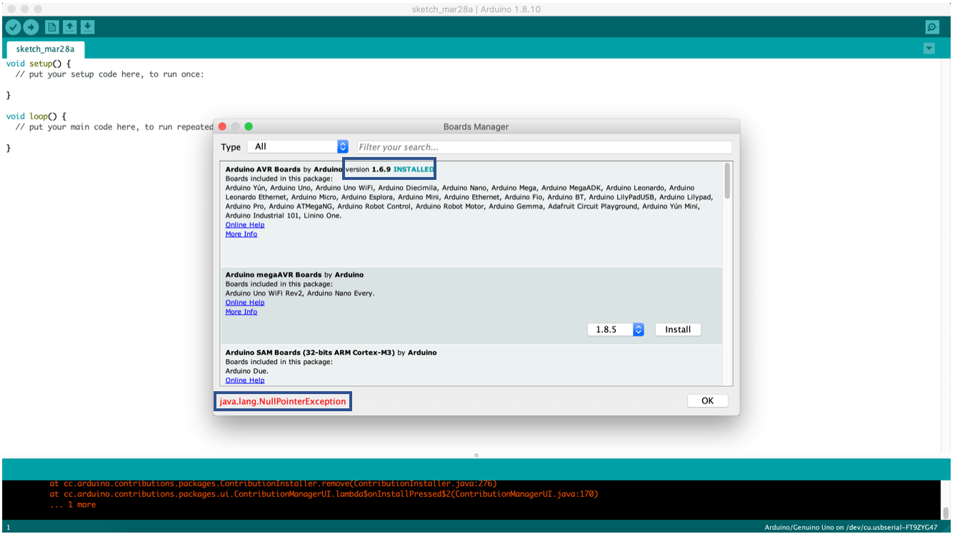
I took a lot of time before I found the solution, and begin able to work or uploading codes. This link helped me in debugging and finding the solution.
The solution to this problem is to install the newest version, from board manager –> update/ install select version.
but whenever I tried to do so, I’m getting the error shown above as I mentioned before. The suggested solution was to delete the 1.6.9 version, and easiest way to find and delete it, to open one of the codes as shown below the steps:
Select an Arduino UNO board from the Tools > Board menu.
File > Examples > EEPROM > eeprom_clear
Sketch > Show Sketch Folder
So I just have to move up folders until I get to the Arduino version 1.6.9, after I reach the folder and delete it, I restart the Arduino IDE.
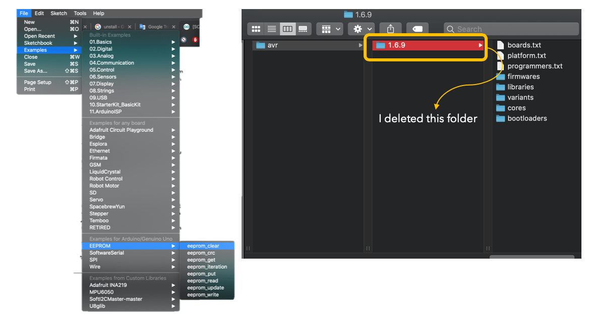
Afterward, I reopened Ardunio IDE, and go to the Tools –> Board –> Board Manager, I found the lastest version I needed already installed. Finally the problem was solved.

Next, I tried to re-upload the code and upload was done successfully, but I’m getting another error now.

The second error I was having, related to the I2C communication between the sensor and the board as shown below screenshot of the serial monitor with the error:
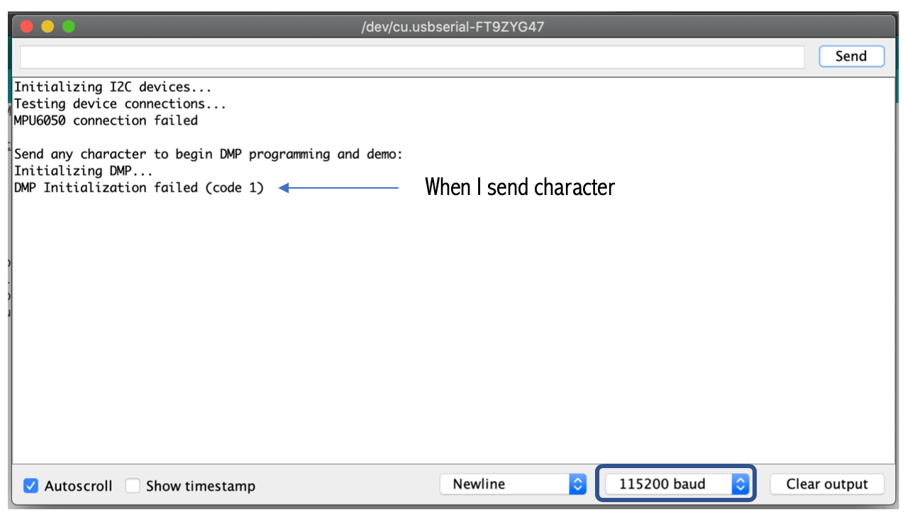
I did set the baud rate to 115200 as this code working with this baud. the code start by testing device connection its shows MPU6050 connection failed. However, I read on the internet that some people had the same message but when they send any character the program working well, so I tried to send by still the code not working.
As MPU6050 using the I2C connection, Instructor Hashim advice me to check the pull-up resistors. The pull-up resistors are usually in the range of 5kΩ to 10kΩ, they are needed for each of the two bus lines.
An I2C bus will not operate without the pull-up resistors. Because when there is no activity on the bus, the clock and data lines must be in the high state. If this is not the case, the data transfers can not be initiated.
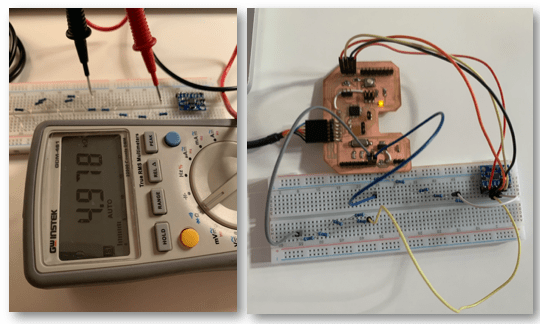
So I did add external pull resistors in case the embedded resistors in the MPU6050 module is damaged.
The exact resistor value needed to be was not available with me, As I’m working from home, but happily, I found in my Arduino kit 10kΩ and 1kΩ resistors.
I did start by trying 10kΩ and I almost was near to burning the sensor smoke start coming out from the sensor, I removed from the laptop quickly.
Hopefully, the sensor has not burned the power LED is still on when I plugin.
Next, I did connect 5 resistors in series of the 1kΩ value in the breadboard and I checked using the multimeter it the value of the total resistor is correct, it was ~ 5kΩ, most of the people using 4.7kΩ for pull-resistors so it was fine.
But still, the error was there, and it was the same with and without the resistors.
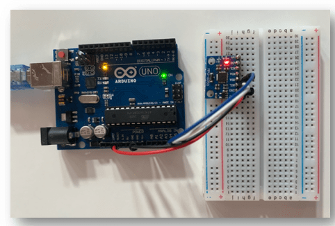
Then, I tried the sensor with Arduino UNO board in case the problem is from my board, but still the error was there.
I tried different 2 extra code to check if the problem from the code or something else all the codes were not working properly:
// I2C device class (I2Cdev) demonstration Arduino sketch for MPU6050 class
// 10/7/2011 by Jeff Rowberg <jeff@rowberg.net>
// Updates should (hopefully) always be available at https://github.com/jrowberg/i2cdevlib
//
// Changelog:
//      2013-05-08 - added multiple output formats
//                 - added seamless Fastwire support
//      2011-10-07 - initial release

/* ============================================
I2Cdev device library code is placed under the MIT license
Copyright (c) 2011 Jeff Rowberg

Permission is hereby granted, free of charge, to any person obtaining a copy
of this software and associated documentation files (the "Software"), to deal
in the Software without restriction, including without limitation the rights
to use, copy, modify, merge, publish, distribute, sublicense, and/or sell
copies of the Software, and to permit persons to whom the Software is
furnished to do so, subject to the following conditions:

The above copyright notice and this permission notice shall be included in
all copies or substantial portions of the Software.

THE SOFTWARE IS PROVIDED "AS IS", WITHOUT WARRANTY OF ANY KIND, EXPRESS OR
IMPLIED, INCLUDING BUT NOT LIMITED TO THE WARRANTIES OF MERCHANTABILITY,
FITNESS FOR A PARTICULAR PURPOSE AND NONINFRINGEMENT. IN NO EVENT SHALL THE
AUTHORS OR COPYRIGHT HOLDERS BE LIABLE FOR ANY CLAIM, DAMAGES OR OTHER
LIABILITY, WHETHER IN AN ACTION OF CONTRACT, TORT OR OTHERWISE, ARISING FROM,
OUT OF OR IN CONNECTION WITH THE SOFTWARE OR THE USE OR OTHER DEALINGS IN
THE SOFTWARE.
===============================================
*/

// I2Cdev and MPU6050 must be installed as libraries, or else the .cpp/.h files
// for both classes must be in the include path of your project
#include "I2Cdev.h"
#include "MPU6050.h"

// Arduino Wire library is required if I2Cdev I2CDEV_ARDUINO_WIRE implementation
// is used in I2Cdev.h
#if I2CDEV_IMPLEMENTATION == I2CDEV_ARDUINO_WIRE
    #include "Wire.h"
#endif

// class default I2C address is 0x68
// specific I2C addresses may be passed as a parameter here
// AD0 low = 0x68 (default for InvenSense evaluation board)
// AD0 high = 0x69
MPU6050 accelgyro;
//MPU6050 accelgyro(0x69); // <-- use for AD0 high

int16_t ax, ay, az;
int16_t gx, gy, gz;


// uncomment "OUTPUT_READABLE_ACCELGYRO" if you want to see a tab-separated
// list of the accel X/Y/Z and then gyro X/Y/Z values in decimal. Easy to read,
// not so easy to parse, and slow(er) over UART.
#define OUTPUT_READABLE_ACCELGYRO

// uncomment "OUTPUT_BINARY_ACCELGYRO" to send all 6 axes of data as 16-bit
// binary, one right after the other. This is very fast (as fast as possible
// without compression or data loss), and easy to parse, but impossible to read
// for a human.
//#define OUTPUT_BINARY_ACCELGYRO


#define LED_PIN 13
bool blinkState = false;

void setup() {
    // join I2C bus (I2Cdev library doesn't do this automatically)
    #if I2CDEV_IMPLEMENTATION == I2CDEV_ARDUINO_WIRE
        Wire.begin();
    #elif I2CDEV_IMPLEMENTATION == I2CDEV_BUILTIN_FASTWIRE
        Fastwire::setup(400, true);
    #endif

    // initialize serial communication
    // (38400 chosen because it works as well at 8MHz as it does at 16MHz, but
    // it's really up to you depending on your project)
    Serial.begin(38400);

    // initialize device
    Serial.println("Initializing I2C devices...");
    accelgyro.initialize();

    // verify connection
    Serial.println("Testing device connections...");
    Serial.println(accelgyro.testConnection() ? "MPU6050 connection successful" : "MPU6050 connection failed");

    // use the code below to change accel/gyro offset values
    /*
    Serial.println("Updating internal sensor offsets...");
    // -76  -2359   1688    0   0   0
    Serial.print(accelgyro.getXAccelOffset()); Serial.print("\t"); // -76
    Serial.print(accelgyro.getYAccelOffset()); Serial.print("\t"); // -2359
    Serial.print(accelgyro.getZAccelOffset()); Serial.print("\t"); // 1688
    Serial.print(accelgyro.getXGyroOffset()); Serial.print("\t"); // 0
    Serial.print(accelgyro.getYGyroOffset()); Serial.print("\t"); // 0
    Serial.print(accelgyro.getZGyroOffset()); Serial.print("\t"); // 0
    Serial.print("\n");
    accelgyro.setXGyroOffset(220);
    accelgyro.setYGyroOffset(76);
    accelgyro.setZGyroOffset(-85);
    Serial.print(accelgyro.getXAccelOffset()); Serial.print("\t"); // -76
    Serial.print(accelgyro.getYAccelOffset()); Serial.print("\t"); // -2359
    Serial.print(accelgyro.getZAccelOffset()); Serial.print("\t"); // 1688
    Serial.print(accelgyro.getXGyroOffset()); Serial.print("\t"); // 0
    Serial.print(accelgyro.getYGyroOffset()); Serial.print("\t"); // 0
    Serial.print(accelgyro.getZGyroOffset()); Serial.print("\t"); // 0
    Serial.print("\n");
    */

    // configure Arduino LED for
    pinMode(LED_PIN, OUTPUT);
}

void loop() {
    // read raw accel/gyro measurements from device
    accelgyro.getMotion6(&ax, &ay, &az, &gx, &gy, &gz);

    // these methods (and a few others) are also available
    //accelgyro.getAcceleration(&ax, &ay, &az);
    //accelgyro.getRotation(&gx, &gy, &gz);

    #ifdef OUTPUT_READABLE_ACCELGYRO
        // display tab-separated accel/gyro x/y/z values
        Serial.print("a/g:\t");
        Serial.print(ax); Serial.print("\t");
        Serial.print(ay); Serial.print("\t");
        Serial.print(az); Serial.print("\t");
        Serial.print(gx); Serial.print("\t");
        Serial.print(gy); Serial.print("\t");
        Serial.println(gz);
    #endif

    #ifdef OUTPUT_BINARY_ACCELGYRO
        Serial.write((uint8_t)(ax >> 8)); Serial.write((uint8_t)(ax & 0xFF));
        Serial.write((uint8_t)(ay >> 8)); Serial.write((uint8_t)(ay & 0xFF));
        Serial.write((uint8_t)(az >> 8)); Serial.write((uint8_t)(az & 0xFF));
        Serial.write((uint8_t)(gx >> 8)); Serial.write((uint8_t)(gx & 0xFF));
        Serial.write((uint8_t)(gy >> 8)); Serial.write((uint8_t)(gy & 0xFF));
        Serial.write((uint8_t)(gz >> 8)); Serial.write((uint8_t)(gz & 0xFF));
    #endif

    // blink LED to indicate activity
    blinkState = !blinkState;
    digitalWrite(LED_PIN, blinkState);
}

// (c) Michael Schoeffler 2017, http://www.mschoeffler.de

#include "Wire.h" // This library allows you to communicate with I2C devices.

const int MPU_ADDR = 0x68; // I2C address of the MPU-6050. If AD0 pin is set to HIGH, the I2C address will be 0x69.

int16_t accelerometer_x, accelerometer_y, accelerometer_z; // variables for accelerometer raw data
int16_t gyro_x, gyro_y, gyro_z; // variables for gyro raw data
int16_t temperature; // variables for temperature data

char tmp_str[7]; // temporary variable used in convert function

char* convert_int16_to_str(int16_t i) { // converts int16 to string. Moreover, resulting strings will have the same length in the debug monitor.
  sprintf(tmp_str, "%6d", i);
  return tmp_str;
}

void setup() {
  Serial.begin(9600);
  Wire.begin();
  Wire.beginTransmission(MPU_ADDR); // Begins a transmission to the I2C slave (GY-521 board)
  Wire.write(0x6B); // PWR_MGMT_1 register
  Wire.write(0); // set to zero (wakes up the MPU-6050)
  Wire.endTransmission(true);
}
void loop() {
  Wire.beginTransmission(MPU_ADDR);
  Wire.write(0x3B); // starting with register 0x3B (ACCEL_XOUT_H) [MPU-6000 and MPU-6050 Register Map and Descriptions Revision 4.2, p.40]
  Wire.endTransmission(false); // the parameter indicates that the Arduino will send a restart. As a result, the connection is kept active.
  Wire.requestFrom(MPU_ADDR, 7*2, true); // request a total of 7*2=14 registers

  // "Wire.read()<<8 | Wire.read();" means two registers are read and stored in the same variable
  accelerometer_x = Wire.read()<<8 | Wire.read(); // reading registers: 0x3B (ACCEL_XOUT_H) and 0x3C (ACCEL_XOUT_L)
  accelerometer_y = Wire.read()<<8 | Wire.read(); // reading registers: 0x3D (ACCEL_YOUT_H) and 0x3E (ACCEL_YOUT_L)
  accelerometer_z = Wire.read()<<8 | Wire.read(); // reading registers: 0x3F (ACCEL_ZOUT_H) and 0x40 (ACCEL_ZOUT_L)
  temperature = Wire.read()<<8 | Wire.read(); // reading registers: 0x41 (TEMP_OUT_H) and 0x42 (TEMP_OUT_L)
  gyro_x = Wire.read()<<8 | Wire.read(); // reading registers: 0x43 (GYRO_XOUT_H) and 0x44 (GYRO_XOUT_L)
  gyro_y = Wire.read()<<8 | Wire.read(); // reading registers: 0x45 (GYRO_YOUT_H) and 0x46 (GYRO_YOUT_L)
  gyro_z = Wire.read()<<8 | Wire.read(); // reading registers: 0x47 (GYRO_ZOUT_H) and 0x48 (GYRO_ZOUT_L)

  // print out data
  Serial.print("aX = "); Serial.print(convert_int16_to_str(accelerometer_x));
  Serial.print(" | aY = "); Serial.print(convert_int16_to_str(accelerometer_y));
  Serial.print(" | aZ = "); Serial.print(convert_int16_to_str(accelerometer_z));
  // the following equation was taken from the documentation [MPU-6000/MPU-6050 Register Map and Description, p.30]
  Serial.print(" | tmp = "); Serial.print(temperature/340.00+36.53);
  Serial.print(" | gX = "); Serial.print(convert_int16_to_str(gyro_x));
  Serial.print(" | gY = "); Serial.print(convert_int16_to_str(gyro_y));
  Serial.print(" | gZ = "); Serial.print(convert_int16_to_str(gyro_z));
  Serial.println();

  // delay
  delay(1000);
}
Moreover, I did run code to scan if there is connected I2C device, the code reference:
// I2C Scanner

#include <Wire.h>

void setup() {
Serial.begin (9600);
Serial.println ();
Serial.println ("I2C scanner. Scanning ...");
byte count = 0;

Wire.begin();
for (byte i = 8; i < 120; i++)
{ Wire.beginTransmission (i);
if (Wire.endTransmission () == 0)
{
Serial.print ("Found address: ");
Serial.print (i, DEC);
Serial.print (" (0x");
Serial.print (i, HEX);
Serial.println (")");
count++;
delay (1);
} // end of good response
} // end of for loop
Serial.println ("Done.");
Serial.print ("Found ");
Serial.print (count, DEC);
Serial.println (" device(s).");
}

void loop() {}
Sadly with all attempts I made to let the sensor works it did not work, I read a lot of articles to try to fix it but without avail.
The final conclusion I came with as I mention before it’s a hardware problem.
This week I was planning to finish the assignment as quickly as possible, to catch up on other stuff I didn’t complete. as finalizing idea for my final project, but it’s okay at least I was trying.
“Defeat is not the worst of failures. Not to have tried is the true failure.” ― George E. Woodberry ____
As the sensor I was planning to use to didn’t work, and I have Arduino kit there are some sensors coming with it, I found a water sensor so think I will try to test it.
First, I did watch and follow this tutorial to test the sensor.
The datasheet of the water sensor had a lot of useful information about it, water sensor is used to detect the amount of water induced contact between the grounded and sensor traces, Moreover, this sensor is compatible with Arduino UNO、Arduino mega2560、 Arduino ADK, etc.
Water sensor can:
Measures water level through with a series of exposed parallel wires stitch to measure the water size.
Change the water size to an analog signal, and output analog value that can directly be used in the program function.
Function as a water level alarm.
Three pins are needed for the connection:
VCC.
GND.
Analog input.
The below codes measures the amount of water. Zero indicates no water and as I increase the water the reading is increasing. I did try to run two codes for testing purpose but both of them are doing the same job.
int h20 = 0;


void setup() {

  pinMode(h20, INPUT);

  Serial.begin(9600);


}


void loop() {

 int i = analogRead(h20);

 Serial.println(i);

 delay(1000);

}/*
Analog input, analog output, serial output
Reads an analog input pin, maps the result to a range from 0 to 255 and uses
the result to set the pulse width modulation (PWM) of an output pin.
Also prints the results to the Serial Monitor.
The circuit:
- potentiometer connected to analog pin 0.
Center pin of the potentiometer goes to the analog pin.
side pins of the potentiometer go to +5V and ground
- LED connected from digital pin 9 to ground
created 29 Dec. 2008
modified 9 Apr 2012
by Tom Igoe
This example code is in the public domain.
http://www.arduino.cc/en/Tutorial/AnalogInOutSerial
*/
// These constants won't change. They're used to give names to the pins used:
const int analogInPin = A0; // Analog input pin that the potentiometer is attached to
const int analogOutPin = 9; // Analog output pin that the LED is attached to
int sensorValue = 0; // value read from the pot
int outputValue = 0; // value output to the PWM (analog out)
void setup() {
// initialize serial communications at 9600 bps:
Serial.begin(9600);
}
void loop() {
// read the analog in value:
sensorValue = analogRead(analogInPin);
// map it to the range of the analog out:
outputValue = map(sensorValue, 0, 1023, 0, 255);
// change the analog out value:
analogWrite(analogOutPin, outputValue);
// print the results to the Serial Monitor:
Serial.print("sensor = ");
Serial.print(sensorValue);
Serial.print("\t output = ");
Serial.println(outputValue);
// wait 2 milliseconds before the next loop for the analog-to-digital
// converter to settle after the last reading:
delay(2);
}
| Files | Link |
|---|---|
| I2C development library. | |
| MPU-6050 library. |
