Project Proposal
Research
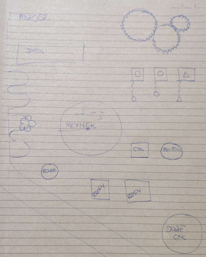
My first idea is inspired by sensory boards that are available on the market. The thing that made me make on own boards is price of the available boards on the makert and lack of electronic accesories.Sketches
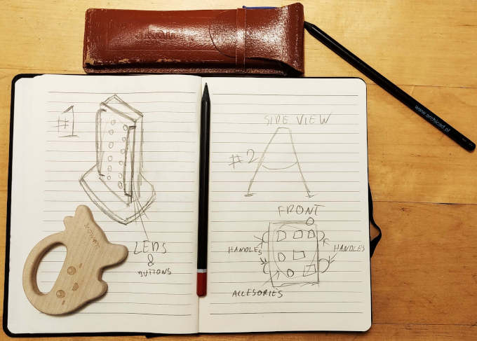
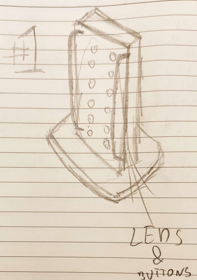
Sketch of the first idea.
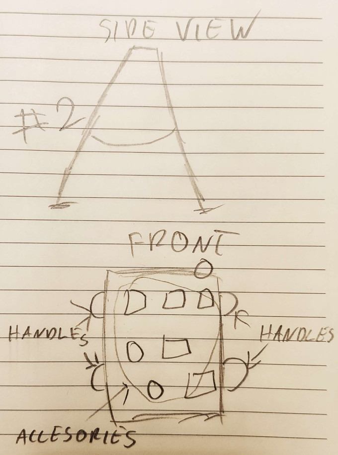
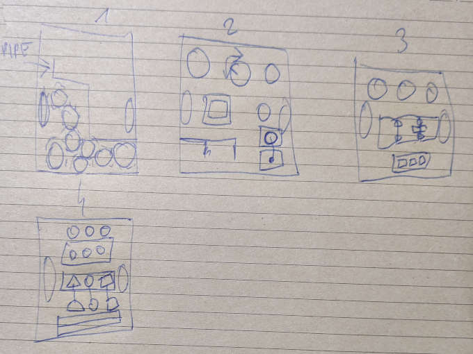
Sketch of the second idea.
This idea stuck with me for few weeks. In meantime I have started to add some more components into it to make it more complex.
Project Developement
After few improvements I realised I have made it a bit overloaded with stuff and things. So the idea got recuded.During work over weekly assigments I was still taking few minutes to think about the final project and how it should looks like.
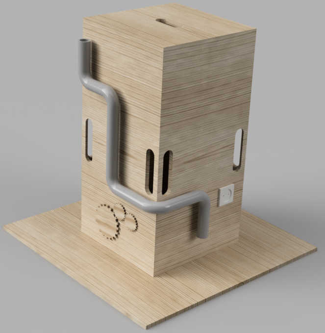
One day a very crazy idea came up to my mind. I designed the board to look more like a big monolith...
Fusion 360 design render:
But after I showed it to my wife I had to completly redesign it and change the way of my thinking. My wife told me that she would rather get something way smaller, even maybe "portable ?". I tought it might be cool to be able to take such "moblie sensory board" everywhere.
So I started designing and trying different things. In the end I came up with very simple idea.
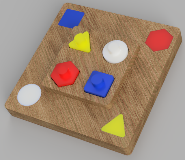
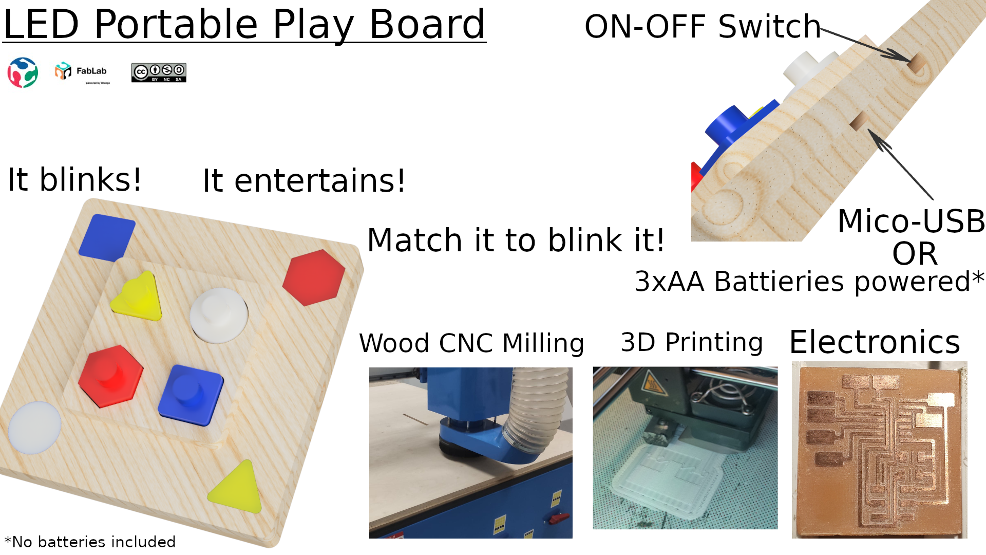
Maybe the design is not so small to make it completly portable but it have internal power source with option to be supplied externaly.
I think about this project and design as a beginning of some bigger project that will produce a small and complex protable , interactive sensory board.
This prototype will let me gain some experience in designing the sensory boards and understanding the behaviour of toddlers, in my son's age.
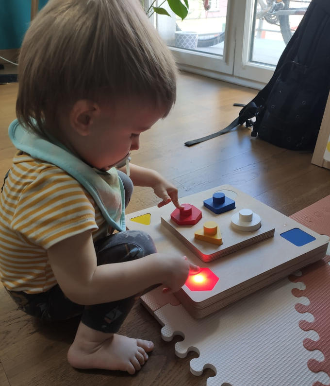
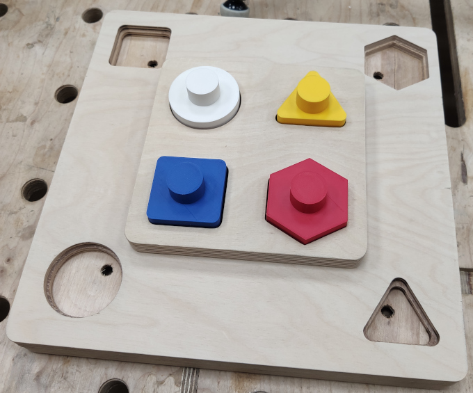
The idea behind the board is very simple. 4 different shapes, 4 wholes with shapes and buttons and the end of the holes. Each button lights up the LED on the board to encurage the toddler to play with the board.
Final Project Fabrication
Fusion 360 Design
The project I have started with 3D design in Fusion 360.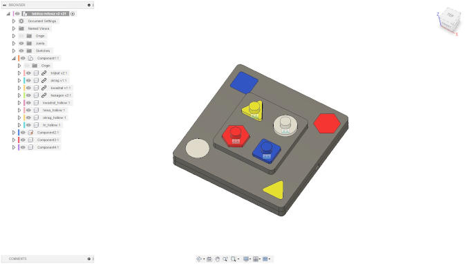
3D printing
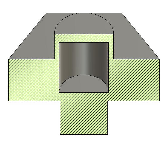
All four shapes that are used to be pressed into the holes were 3D printed. Also the covers for LED lights where 3D printed with a thin wall so the LED light might come through.The shapes also have a empty space inside, inside it during the print I added steel screw nuts so it might work also as a rattle.
Milling
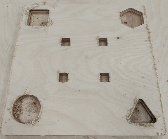
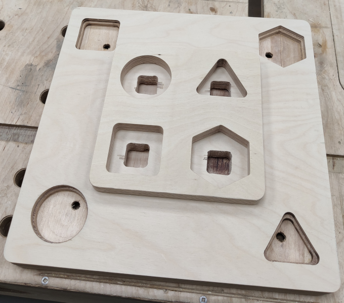
The main body of the board is milled in 18mm ply wood. Path files for were made in Fusion 360 and milled on our big CNC Milling Machine. One of the parts right after milling.
PCBs manufacture
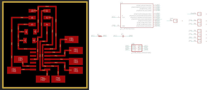
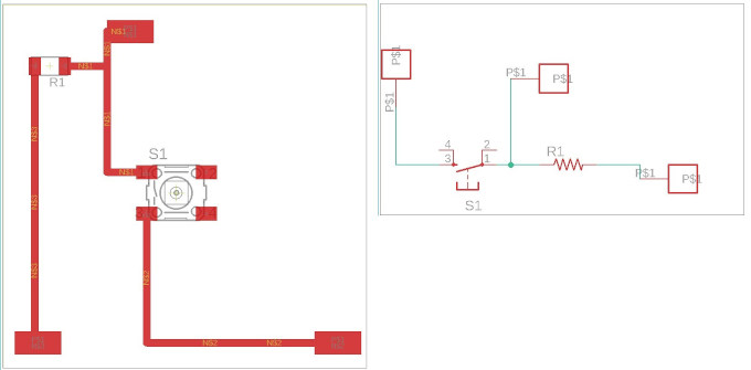
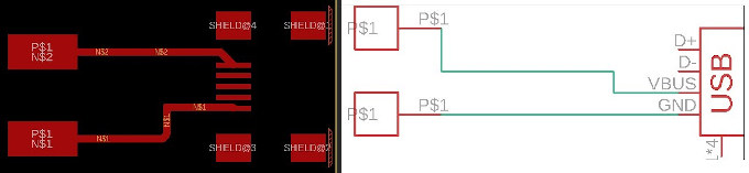
To make the board works I had to make also PCBs. The design was made in Eagle software.
I needed 6 PCBs. One main board with MCU, 4 buttons and one with Micro-USB socket.
After that I had to export the PNG image of the design and process it though mods to get SVG file.
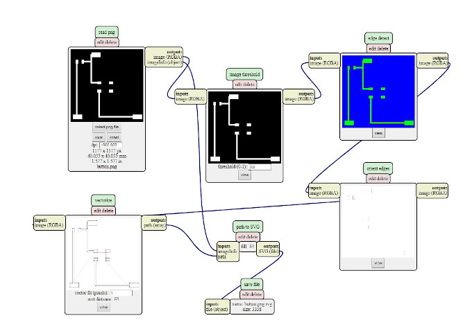
Now I can process the SVG with GIMP to make it into DXF. The ready DXF I process with "Ucancam" software that is designed for our CNC Milling Machine.
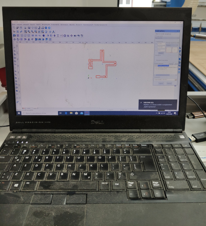
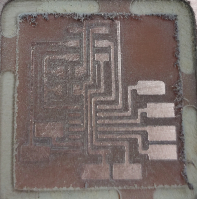
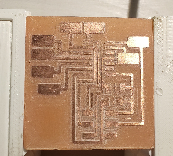
So let's mill it!
Milled main PCB:
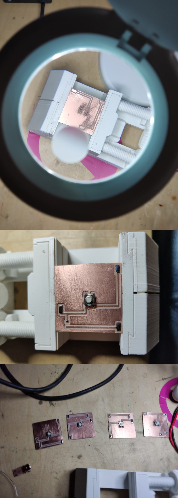
Soldering:
Wood post-processing and gluing
So when I already have all parts I can start to post process the wood and glue the wooden parts togahter.
Cleaning all the sharp egdes to make the toy as safe as possible!
After making sure that there are no splinters that might come out and be a potential danger to the toddler it is time for gluing the parts.
Before gluing I had to make sure that everything fits so I made a tryout fit with 3D printed shapes.
Assembly
Now when the all parts are ready it is time to assemble the toy.
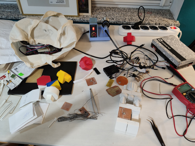
But 1st I need to take care of the mess...
As 1st I placed the button PCBs and USB.
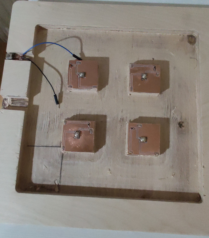
Then main board and some cables.
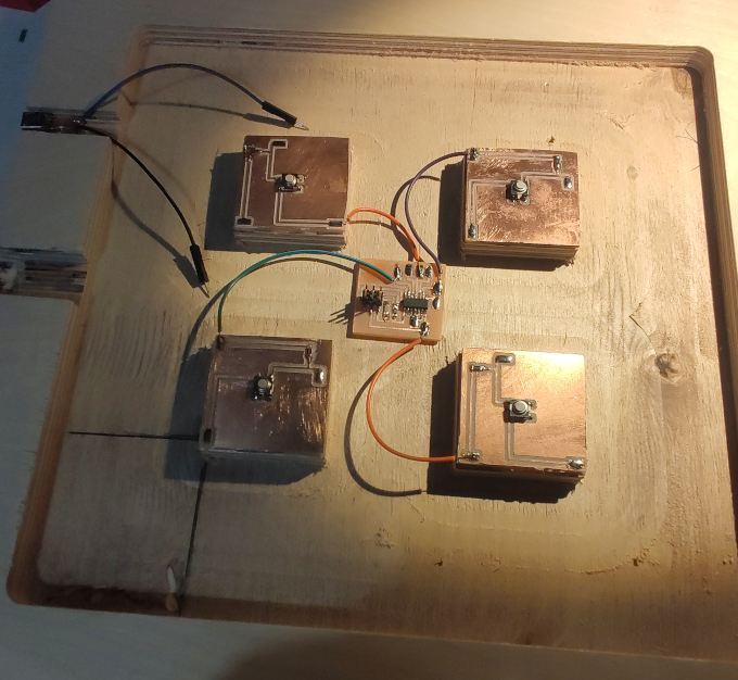
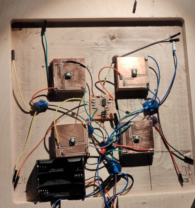
And even more cables... At that point I realised that my cable management skill is not so good. I need to work on that in future projects.
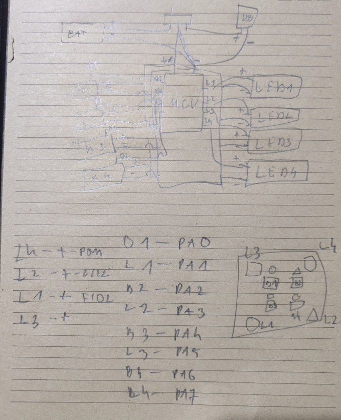
To make sure that I dont get lost in the cables and pins I made myself a sketch with a "map" for calbes and pins :)
After the assembly is half done I made some testing with premade sketch to check if everything is going OK.
After connecting all the cables I connected my FabISP that I made in previus assigments and uploaded the code that I wrote before:
	const int ledPin1 = 5; //LED triangle
const int ledPin2 = 1; //LED rectangle
const int ledPin3 = 7; //LED circle
const int ledPin4 = 3; //LED hexagon
const int buttonPin1 = 4; //button triangle
const int buttonPin2 = 0; //button rectangle
const int buttonPin3 = 2; //button circle
const int buttonPin4 = 6; //button hexagon
int buttonStatus1 = 0;
int buttonStatus2 = 0;
int buttonStatus3 = 0;
int buttonStatus4 = 0;

void setup() {
  pinMode(ledPin1, OUTPUT);
  pinMode(ledPin2, OUTPUT);
  pinMode(ledPin3, OUTPUT);
  pinMode(ledPin4, OUTPUT);
  pinMode(buttonPin1, INPUT);
  pinMode(buttonPin2, INPUT);
  pinMode(buttonPin3, INPUT);
  pinMode(buttonPin4, INPUT);
}

void loop() {
  buttonStatus1 = digitalRead(buttonPin1)
  buttonStatus2 = digitalRead(buttonPin2)
  buttonStatus3 = digitalRead(buttonPin3)
  buttonStatus4 = digitalRead(buttonPin4)
  if (buttonStatus1 == HIGH) {
    digitalWrite(ledPin1, HIGH);
    delay(100);
    digitalWrite(ledPin1, LOW);
    }
  else if (buttonStatus2 == HIGH) {
    digitalWrite(ledPin2, HIGH);
    delay(100);
    digitalWrite(ledPin2, LOW);
    }
  else if (buttonStatus3 == HIGH) {
    digitalWrite(ledPin3, HIGH);
    delay(100);
    digitalWrite(ledPin3, LOW);
    }
  else if (buttonStatus4 == HIGH) {
    digitalWrite(ledPin4, HIGH);
    delay(100);
    digitalWrite(ledPin4, LOW);
    }
  }
I uploaded the code via Arduino IDE: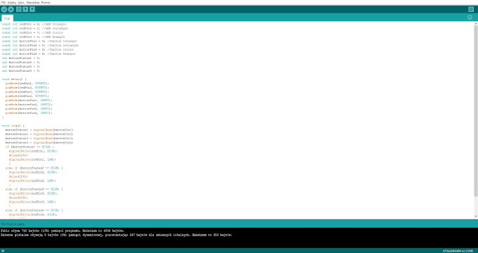
While the code is uploaded and testes all is left is to close the wooden box and give the toy to the "testing department".