
Week_8 - Embedded Programming
Assigment
- group assignment:
- compare the performance and development workflows
- for other architectures
- individual assignment:
- read a microcontroller data sheet
- program your board to do something,
- with as many different programming languages
- and programming environments as possible
Group Assignment
Our task for group in this week was to test the performance and developement workflows for other architectures.
Types of architectures
To make this assigment undestandable for all it is the best to 1st show what kind of different architectures we can use in this assigment and most importantly what is the architecture of microcontroller.
What is microcontroller?
"A microcontroller is essentially a small computer on a chip. Like any computer, it has memory, and can be programmed to do calculations, receive input, and generate output. Unlike a PC, it incorporates memory, a CPU, peripherals and I/O interfaces into a single chip. Microcontrollers are ubiquitous, found in almost every electronic device from ovens to iPods."[1]What is an architecture of microcontroller?
Architecture is a set of attributes of the microcontroller visible by the developer. Those attributes have impact on the logical execution of commands. Example attributes are orders list, in and out operations or methods of addressing the memory.Types of architectures
We can distinguish two most common types:Differences between two Harvad and Von-Neumann architectures
Von-Neumann Architecture Scheme[2]:
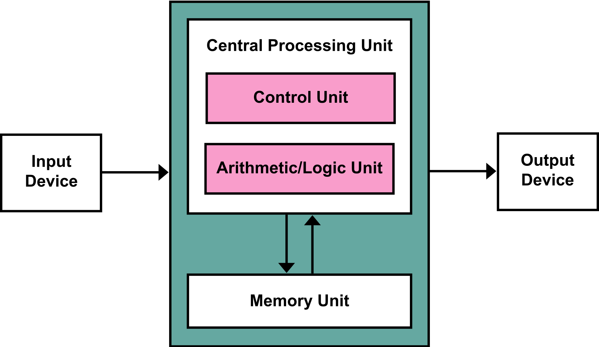 The Von Neumann architecture consists of a single, shared memory for programs and data, a single bus for memory access, an arithmetic unit, and a program control unit. The Von Neumann processor operates fetching and execution cycles seriously.
Harvard Architecture Scheme[3]:

The Harvard architecture has two separate memory spaces dedicated to program code and to data, respectively, two corresponding address buses, and two data buses for accessing two memory spaces. The Harvard processor offers fetching and executions in parallel.
Test
AVR Microcontrollers on Arduino UNO
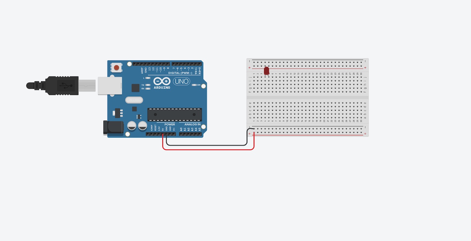
I programed my board and tested on an Arduino in virtual enviroment in Tinkercad Cirtucts on www.tinercad.com. Since I have already a board made there I decided to reuse it. I will make the old board use the LED supplied already plus additional one and say "HELLO WORLD" in Morse code after pushing the button. So one LED on will be a short signal and two LEDs on will be a long signal.
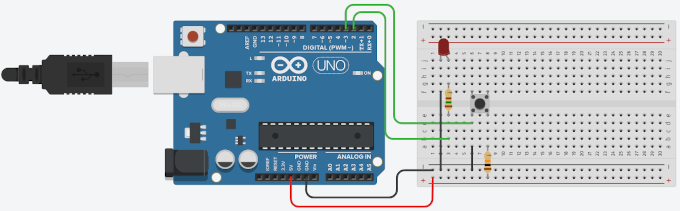
So 1st thing that I have to do is to add new LED to the current setup.
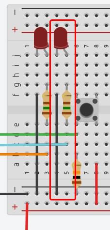
The new LED is connected with the board via turquoise wire and thats make the board complete and ready to get programed.
All is left is to write the code... and yeah, learn Morse Code!!!
So lets 1st look at the Morse Code Graph[1].
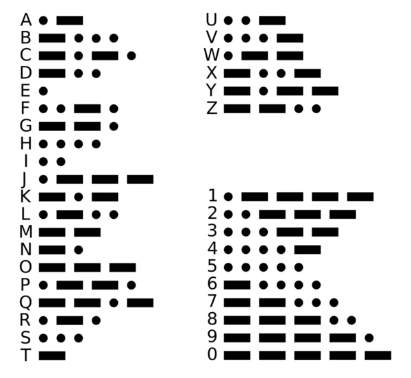
I will use this graph as a reference for making the code.
So lets dig into code! The code we will use C language.
I will start from reusing the previous code so I will simply add the new LED as an output on PIN number 4 (turquoise wire).
		const int buttonPin = 3; //Pin for the button
	const int LEDPin = 2; //Pin for the LED
	const int LEDPin2 = 4; //Pin for the LED2 (added line)

	void setup()
	{
		pinMode(buttonPin, INPUT); //setting the input PIN
		pinMode(LEDPin, OUTPUT); //setting the output PIN
		pinMode(LEDPin2, OUTPUT); //(added line)
		Serial.begin(9600); // Serial console setup
	}
individual assignment:
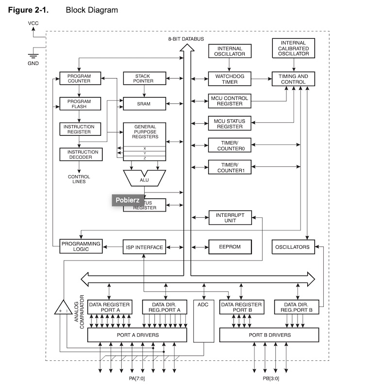
THE data Sheet
Data sheet to attiny is quite a thick book and has a function
a bit like a phone book we don't need to know it all by heart
but we need to know how to move around in it and search for
the most important things. And another plus is that there
are a lot of colorful pictures, which definitely makes it
easier to accept complicated technical knowledge!
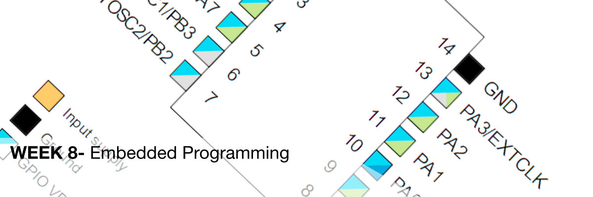
Already on page 13 we encounter the most interesting scheme
or pinout - it can be compared to the road map:)
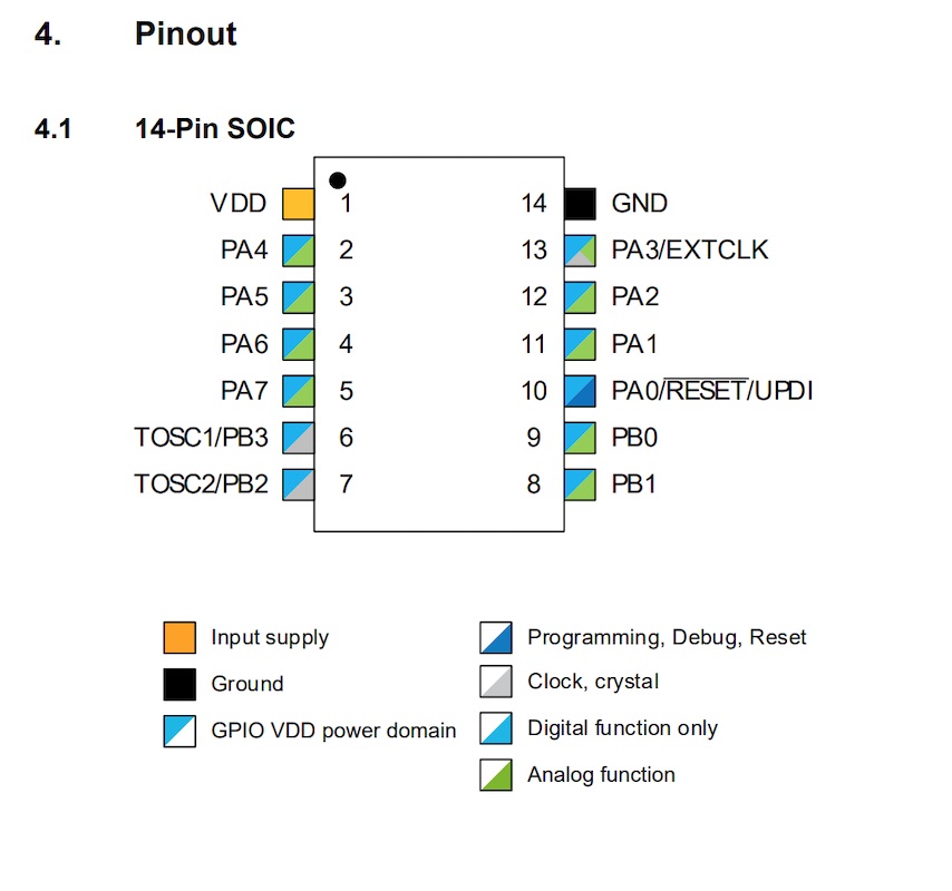
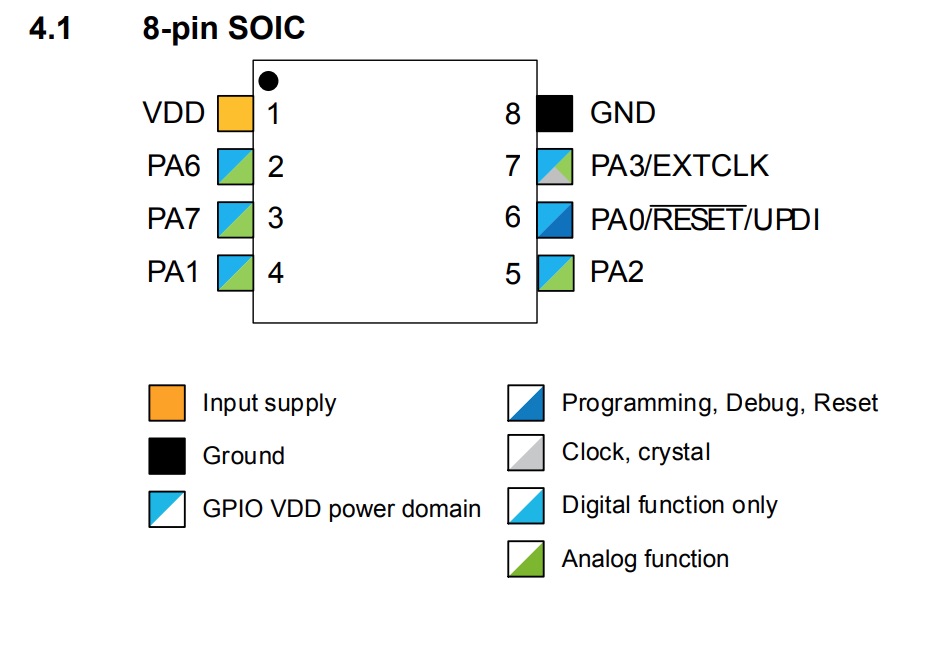
Attiny Diagram
Programing in Tinkercad / Arduino
The project was programmed and tested on Tinkercad Circuits
emulator using simplified C-coding for Arduino.
The idea of the project was to create a virtual dice which,
after pressing a button, will draw any number, and then
blinked the LED as many times as it came out when drawing
any number between 1 and 8.
First, he defined in the code to which pin the button and LED
will be connected and whether there will be input or output.
I connected everything in the diagram using the tutorial on
the button.
I created a loop in which if the button is pressed,
the program will draw a number between 1 and 8.
Once it is drawn, it will repeat a simple code with
flashing LEDs.
Code
	const int button = 10;
	const int LED = 11;
	int num = 0;

	int counter;

	void setup()
	{
	  pinMode(button, INPUT);
	  pinMode(LED, OUTPUT);
	  Serial.begin(9600);
	}

	void loop()
	{
	  if (digitalRead(button) == HIGH) {
	      num = random(1, 8 + 1);
	Serial.println(num);
	    for (counter = 0; counter < num; ++counter) {
	      digitalWrite(LED, HIGH);
	      delay(250); // Wait for 1000 millisecond(s)
	      digitalWrite(LED, LOW);
	      delay(250); // Wait for 1000 millisecond(s)
	    }
	  }
	}
TEST
I thought to myself why not add a 7-segment screen to
this project, which would display the numbers drawn!
I read an article on how to connect such a display.
I found out there which pins to connect with each other
and how the segment screen works. Below is some important
information when writing the code:
Code
			#include "SevSeg.h"
			SevSeg sevseg;

			const int button = 10;
			const int LED = 11;
			int num = 0;

			int counter;

			void setup()
			{
			  pinMode(button, INPUT);
			  pinMode(LED, OUTPUT);
			  Serial.begin(9600);

			  byte numDigits = 1;
			    byte digitPins[] = {};
			    byte segmentPins[] = {6, 5, 2, 3, 4, 7, 8, 9};
			    bool resistorsOnSegments = true;

			    byte hardwareConfig = COMMON_CATHODE;
			    sevseg.begin(hardwareConfig, numDigits, digitPins, segmentPins, resistorsOnSegments);
			    sevseg.setBrightness(90);
			}

			void loop()
			{
			  if (digitalRead(button) == HIGH) {
			      num = random(1, 8 + 1);
			Serial.println(num);
			sevseg.setNumber(num);
			        sevseg.refreshDisplay();
			    for (counter = 0; counter < num; ++counter) {
			      digitalWrite(LED, HIGH);
			      delay(250); // Wait for 1000 millisecond(s)
			      digitalWrite(LED, LOW);
			      delay(250); // Wait for 1000 millisecond(s)
			    }
			  }
			}