
Week_3 - Computer Controlled Cutting
Assigment
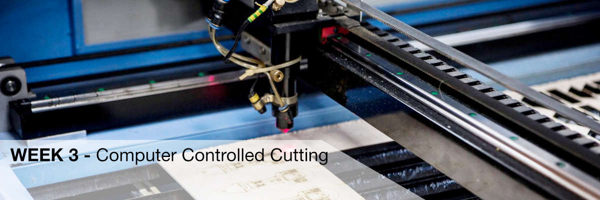
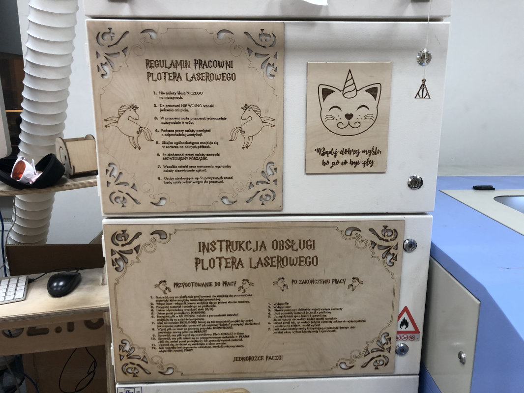
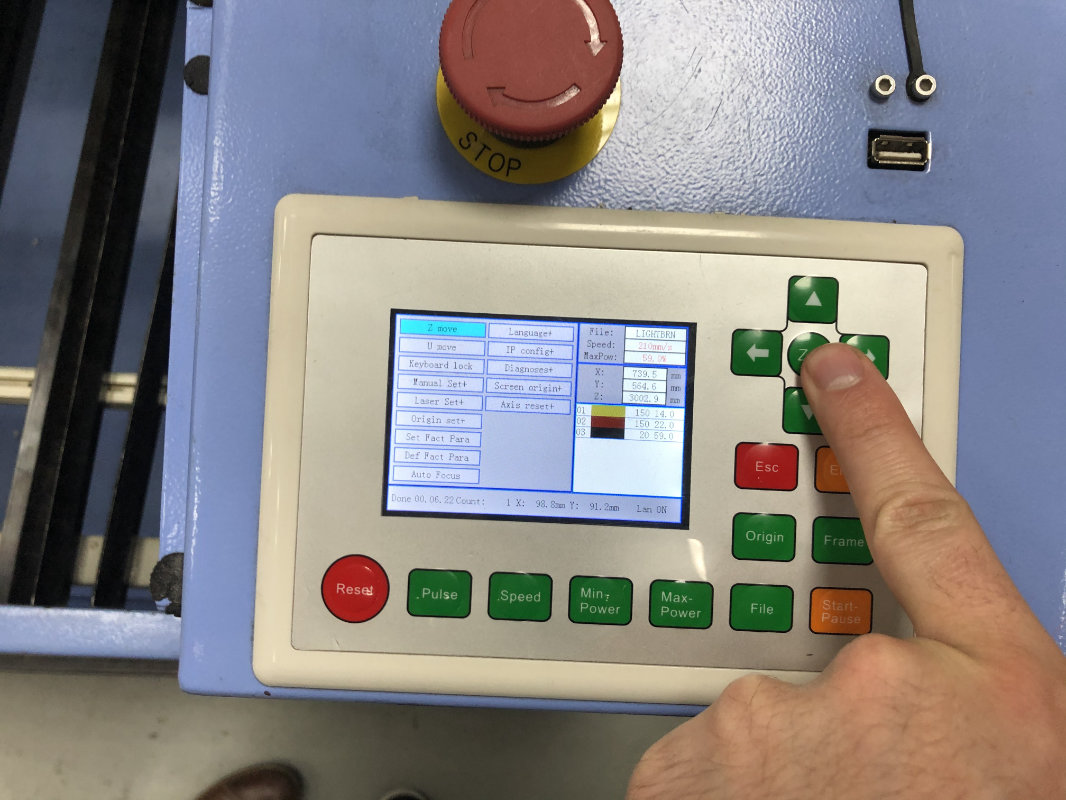
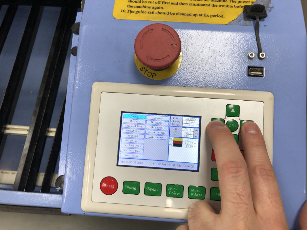
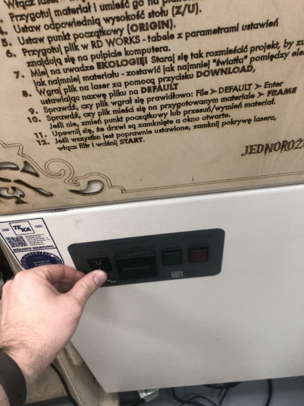
Next week in the fabacademy, this time a little calmer and finally with more practice. The task for this week was to analyze the laser settings in Fablab and create a parametric construction based on repetitive elements cut out on the laser. Moreover, we were supposed to cut something on the vinyl cutter.A few words about the plotter we used:
Kerf
Kerf is defined as the width of material that is removed by a cutting process. It was originally used to describe how much wood was removed by a saw, because the teeth on a saw are bent to the side, so that they remove more material than the width of the saw blade itself, preventing the blade from getting stuck in the wood.
Why kerf width is important

When cutting parts on a CNC plasma or laser machine, you want to produce accurate cut parts, with final dimensions as close as possible to the programmed shape. So if you program a 6” by 6” square, and the plasma arc removes 0.200” of material, as it cuts, then the resulting part is going to be 5.8” by 5.8”. So the actual tool path has to be compensated by 0.100” to the side of the programmed path, all the way around the part.
Rather than re-program the part at a different dimension, the CNC will take care of this automatically just by telling it which direction to offset, and by how much. Most modern CNCs take the actual kerf amount and automatically offset the tool path by 1/2 of that amount, so that the finished part comes out very close to the programmed dimensions. That is why the kerf value is often referred to as “kerf offset”.
source:
https://www.esabna.com/us/en/education/blog/what-is-cutting-kerf.cfm
Kerf testing
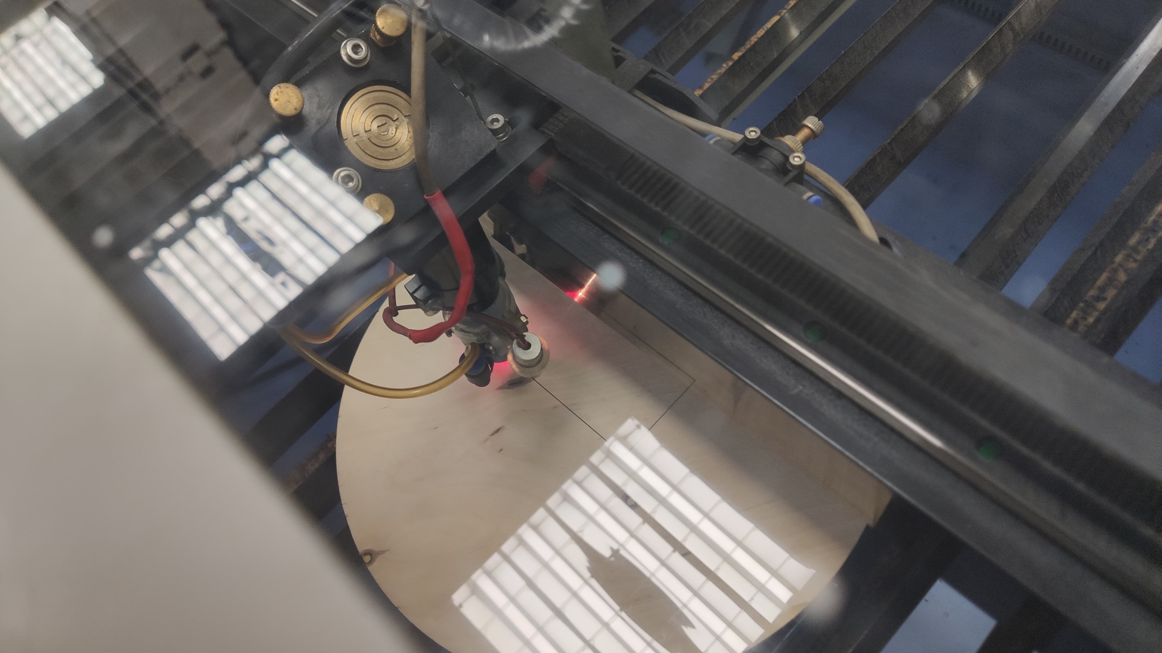
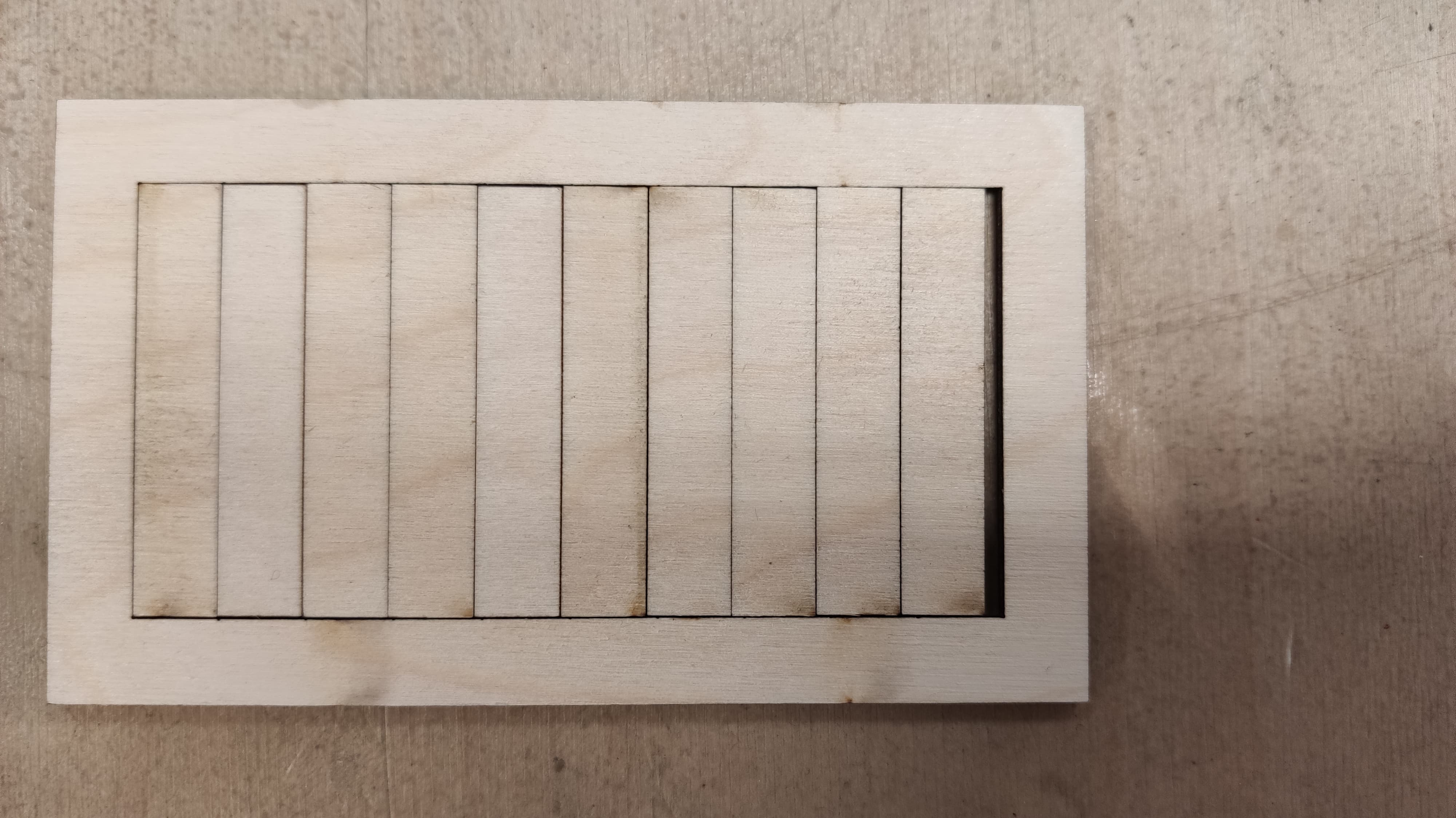
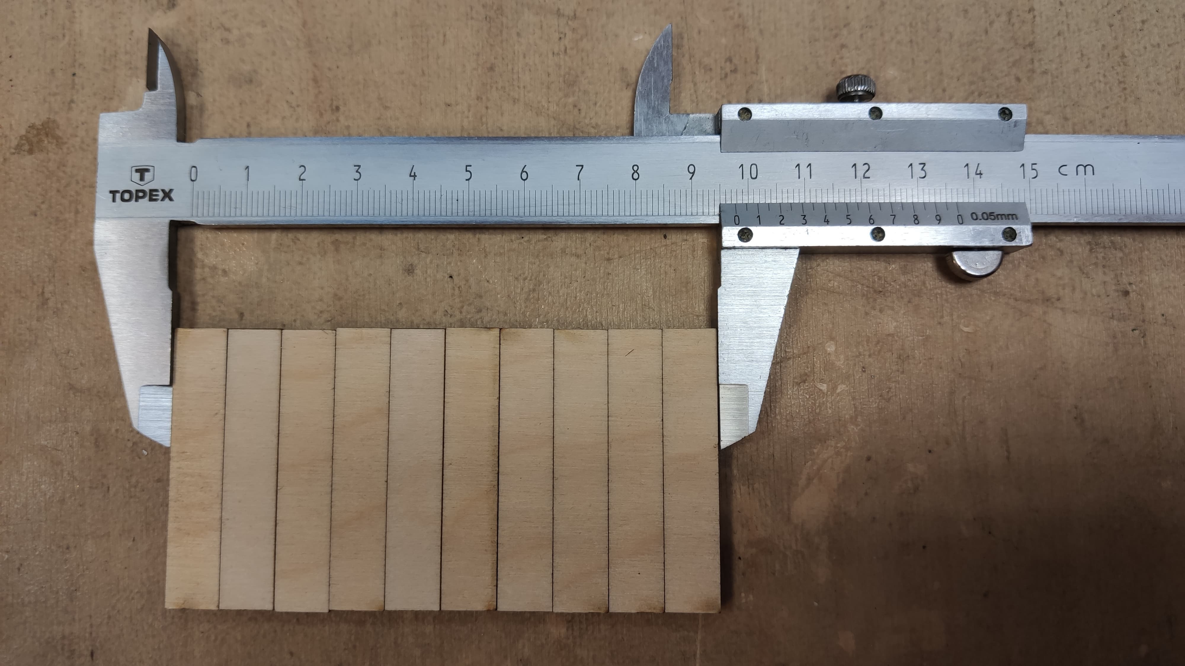
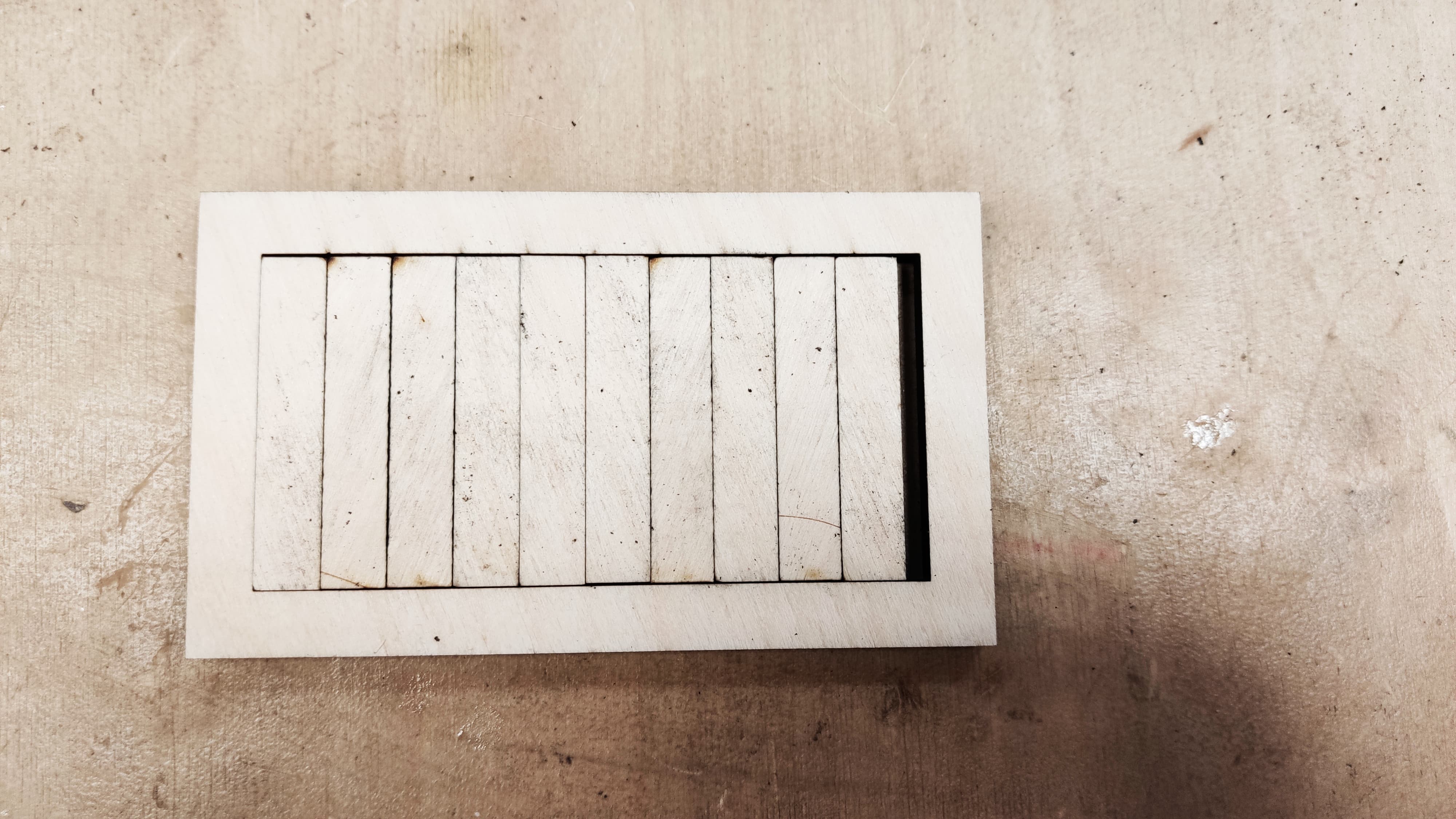
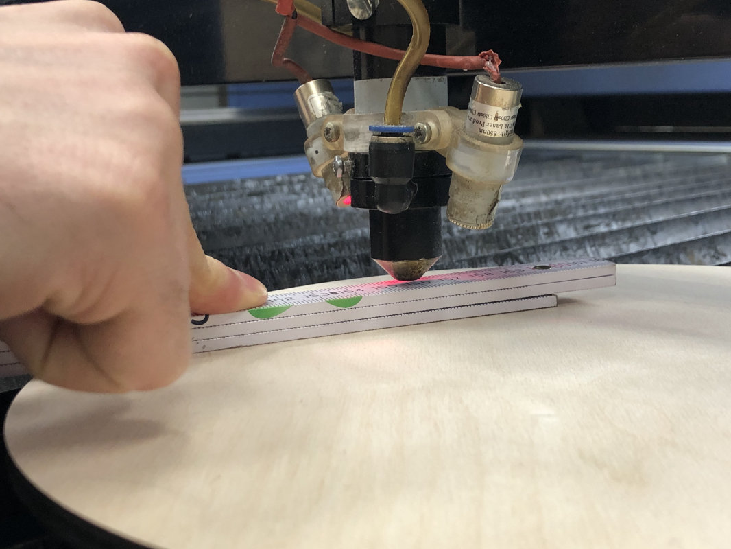
During the tests with kerf we used plywood with a thickness of 3 and 6 mm, which is the material most often used in our Fablab. The test was carried out by cutting out 10 equal-sized rectangles placed next to each other and calculating the difference between the design and the cut out elements on the laser plotter. For the test we used the best possible settings.
The results on 3mm thick plywood did not surprise us. The value that came out is more or less in line with what we assumed. After cutting ten 10 mm rectangles we came out with 97.7 mm of material, i.e. the value of burnt material came out with 2.3 mm divided by the number of cuts (11) gave us kerf value 0.2 mm.
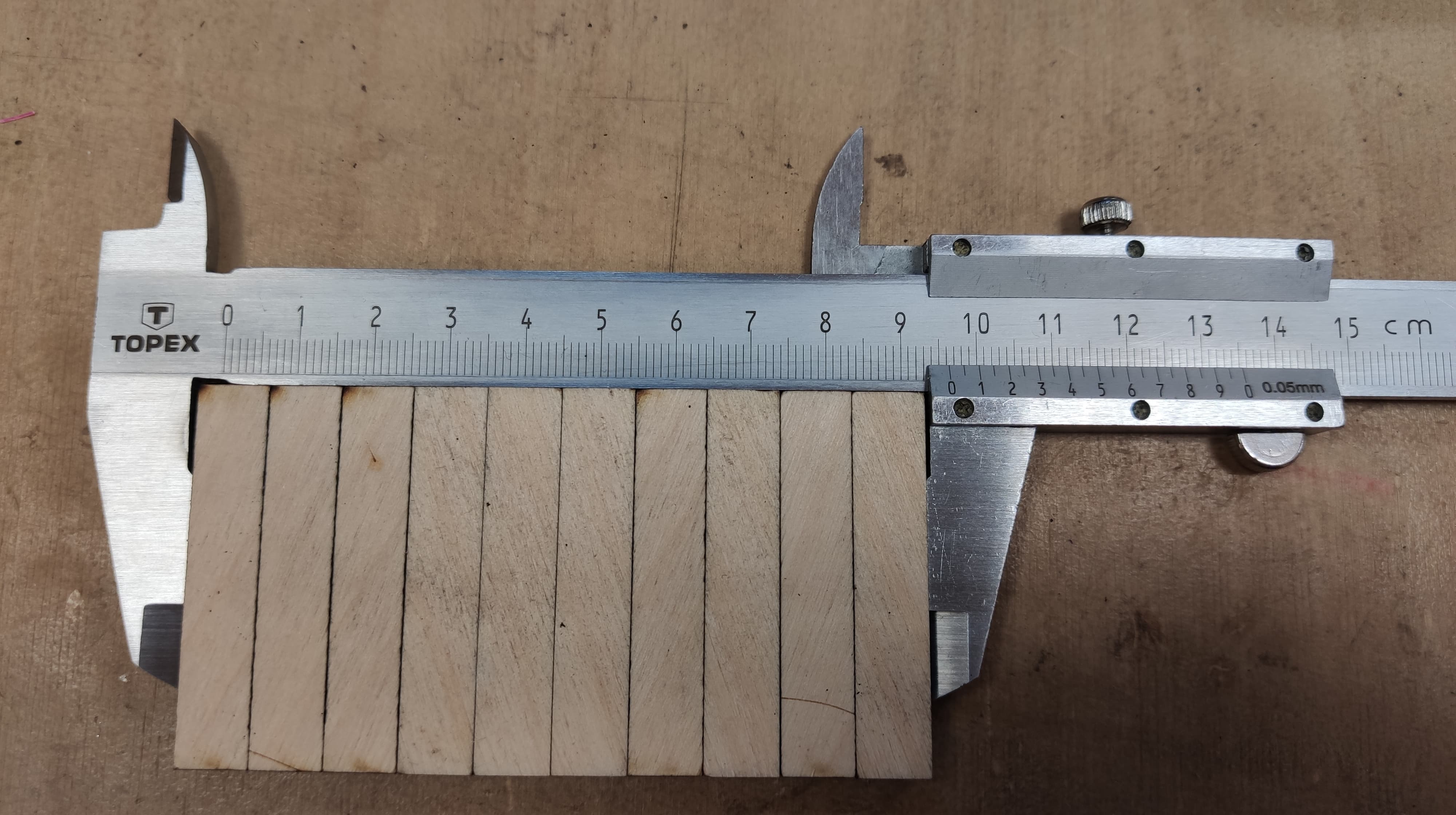
When it comes to 6 mm thick plywood we set Speed 8 mm/sec Power 60%.
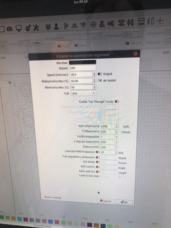
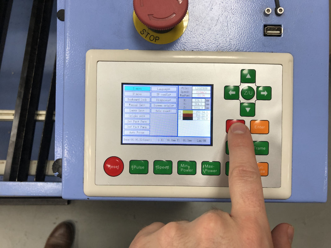
Laser settings
Below is a table with laser settings tested by our fablab community.
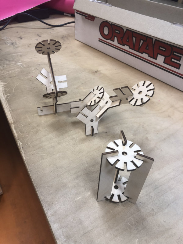
After the laser tests and the Kerf study, it's time for design. I started with a simple object that could be useful in construction workshops. One of the big problems of every fablab is the large number of outcuts from the laser plotter and cnc milling machines. On the former we mainly use 3mm thick plywood on the latter 18mm. The question is why not use these small pieces of plywood to create amazing constructions by workshop participants, just give them the right tool, which in this case will be a connector. I know you can combine everything on hot glue, but sometimes even hot glue may not be enough, and moreover, these connectors can be disassembled and reused after class.
So my assumptions are as follows:
3D Modeling
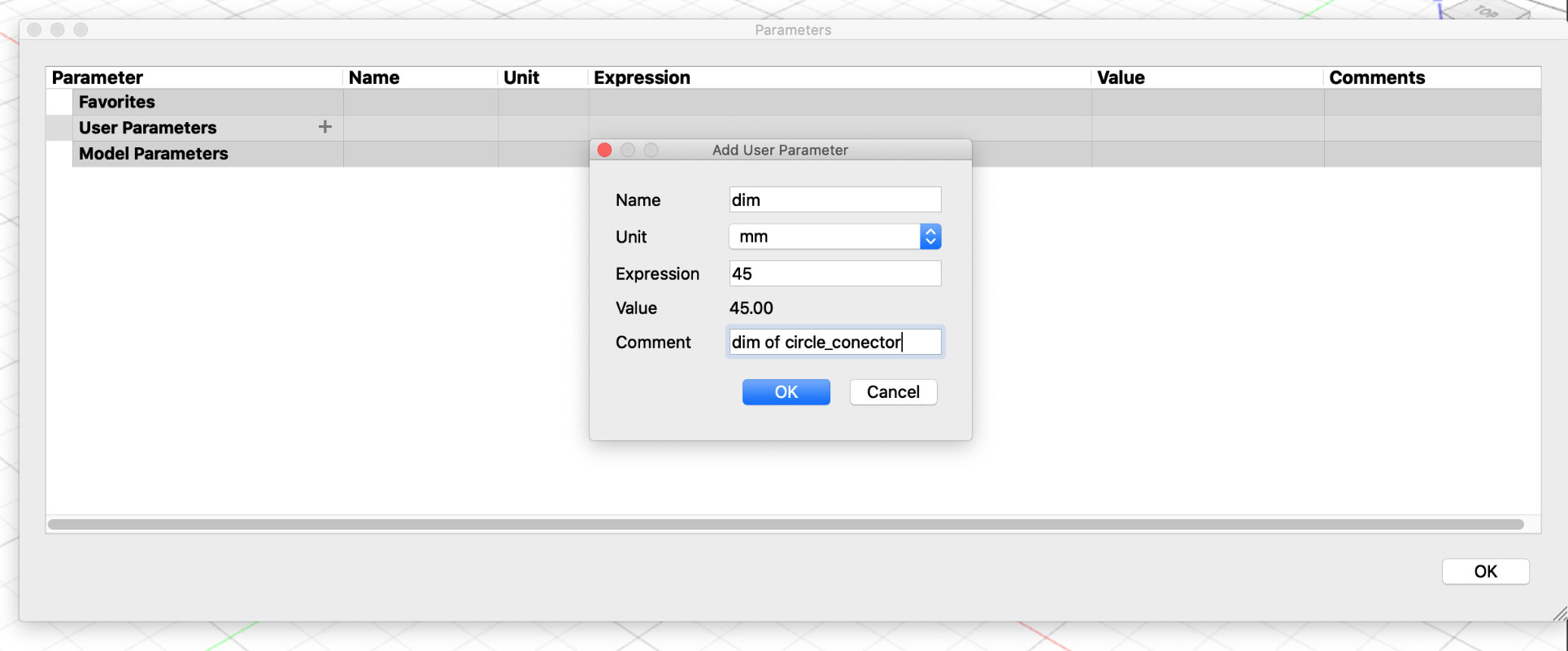
Best practice at the start of parametric design is always to set the parameters and give the initial values with comments.
Modify => Change Parameters
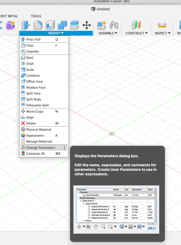
and affter that you have to add a parameters
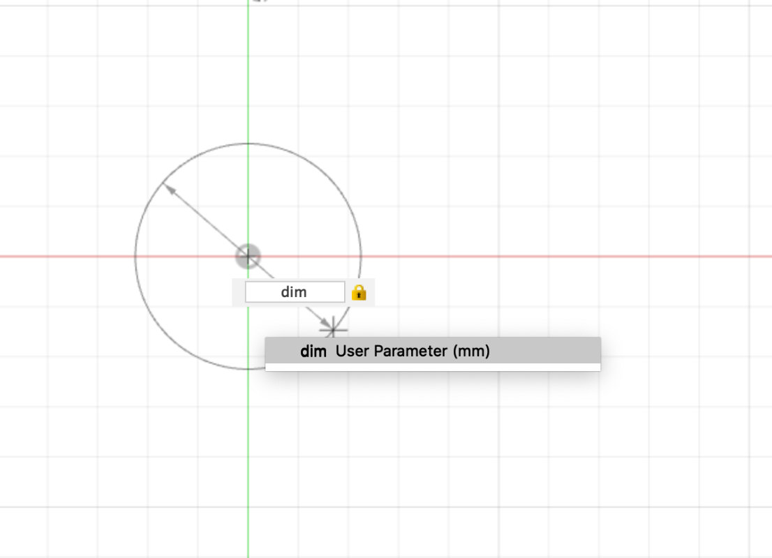
After giving the parameters I drew a circle this time instead
of entering a certain value I gave the variable
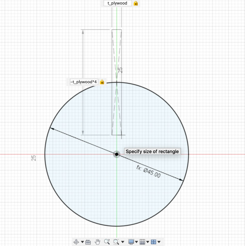
I drew a rectangle of variable material width and created a
pattern using the pattern function.
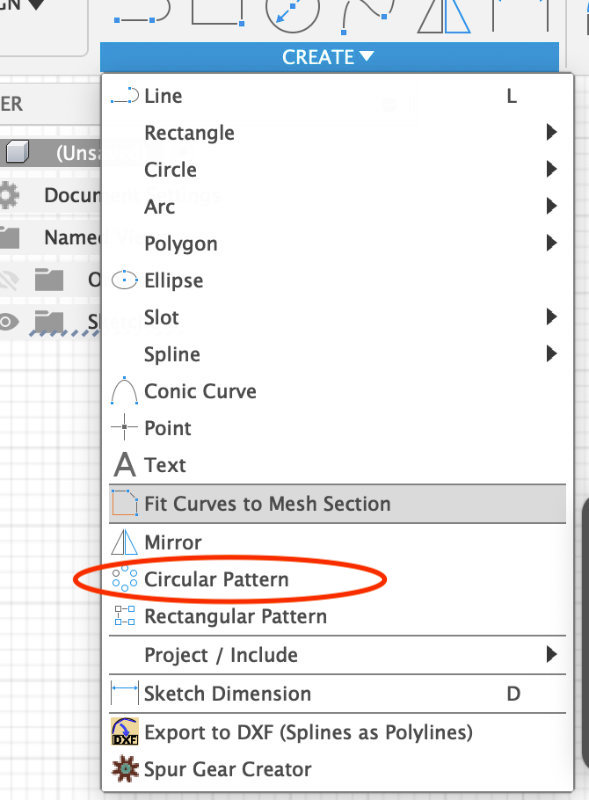
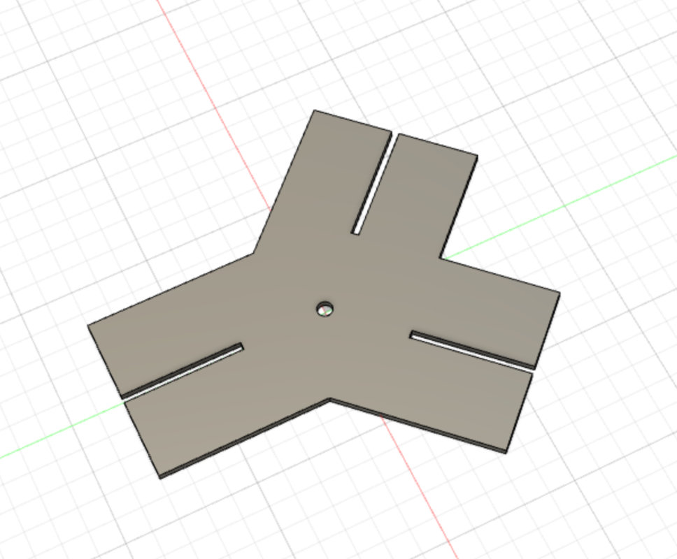
Circular Pattern
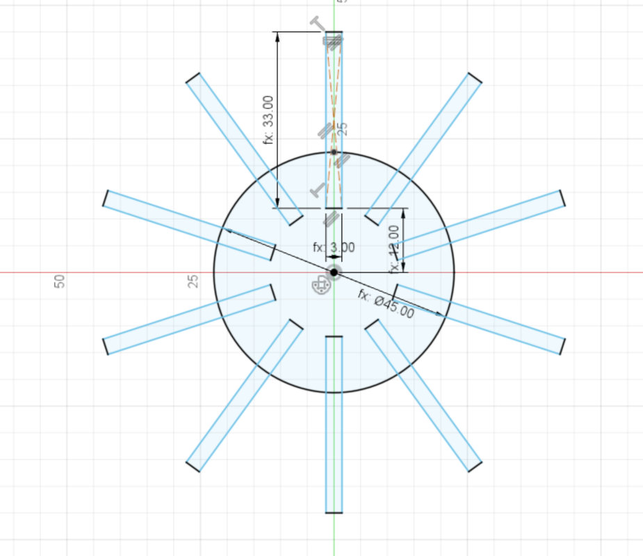
Later, I made a circle in the middle with the diameter of the material thickness to be
used for the later possible mounting of slats or cylindrical profiles.
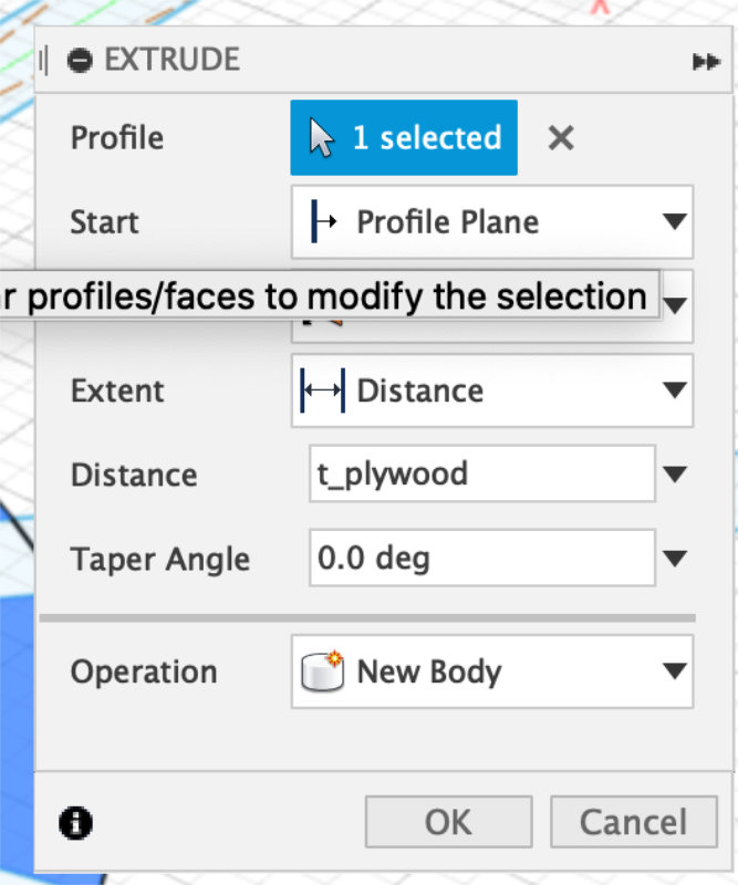
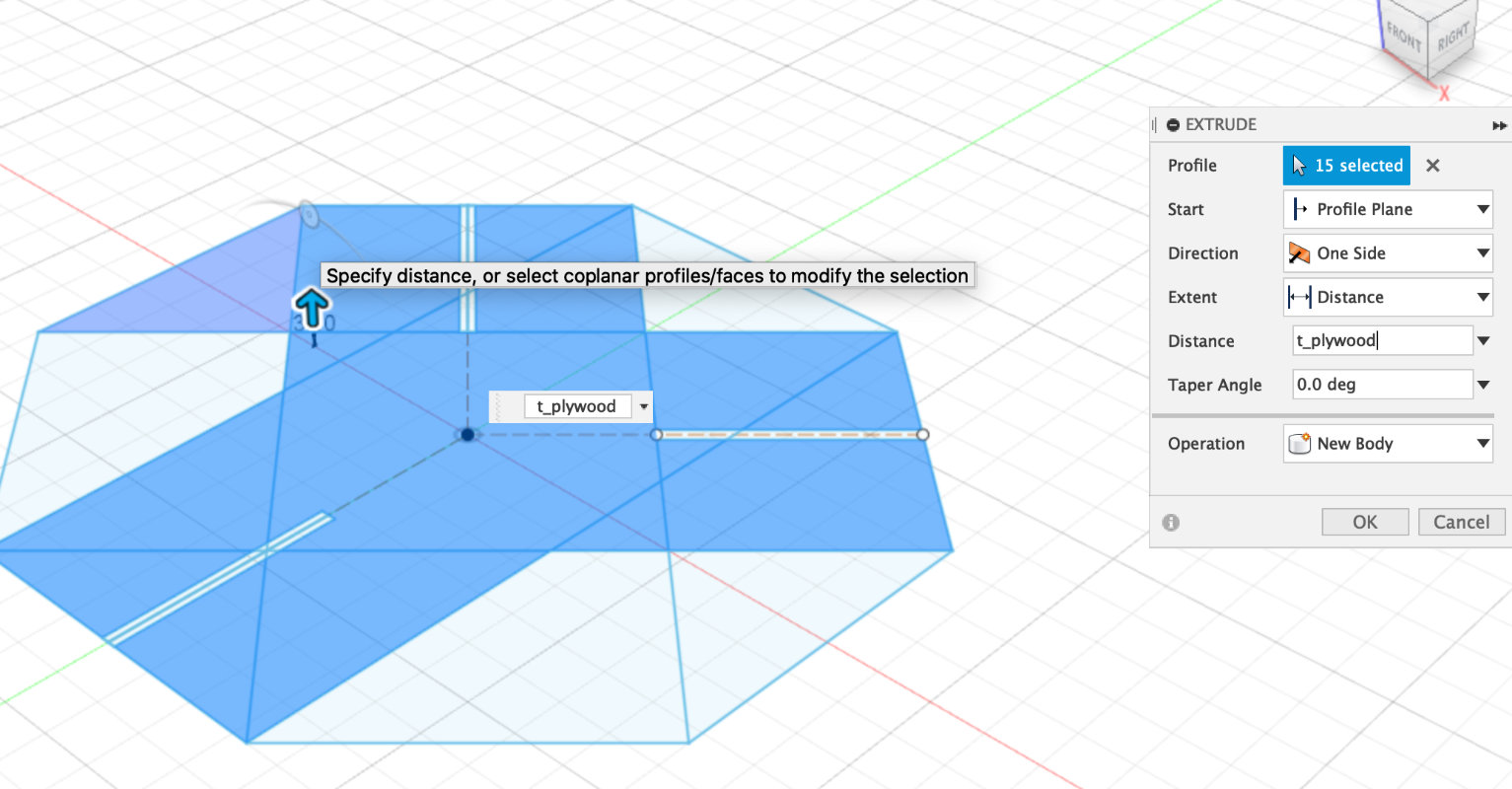
Extrude
After creating this sketch,
I used the extrude function and pulled out the profiles to
a thickness previously defined as the thickness of the material.
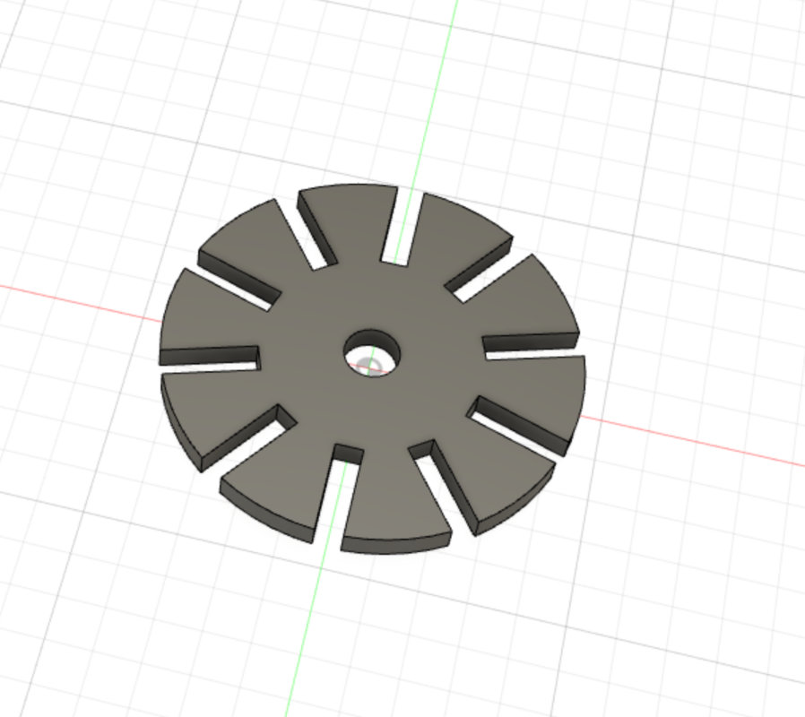
Using the same functions, another connector was created
lasercutting parametric project
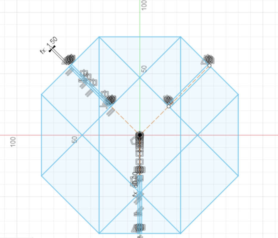
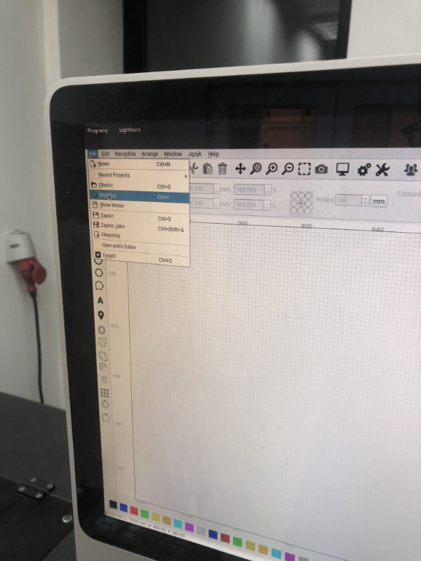
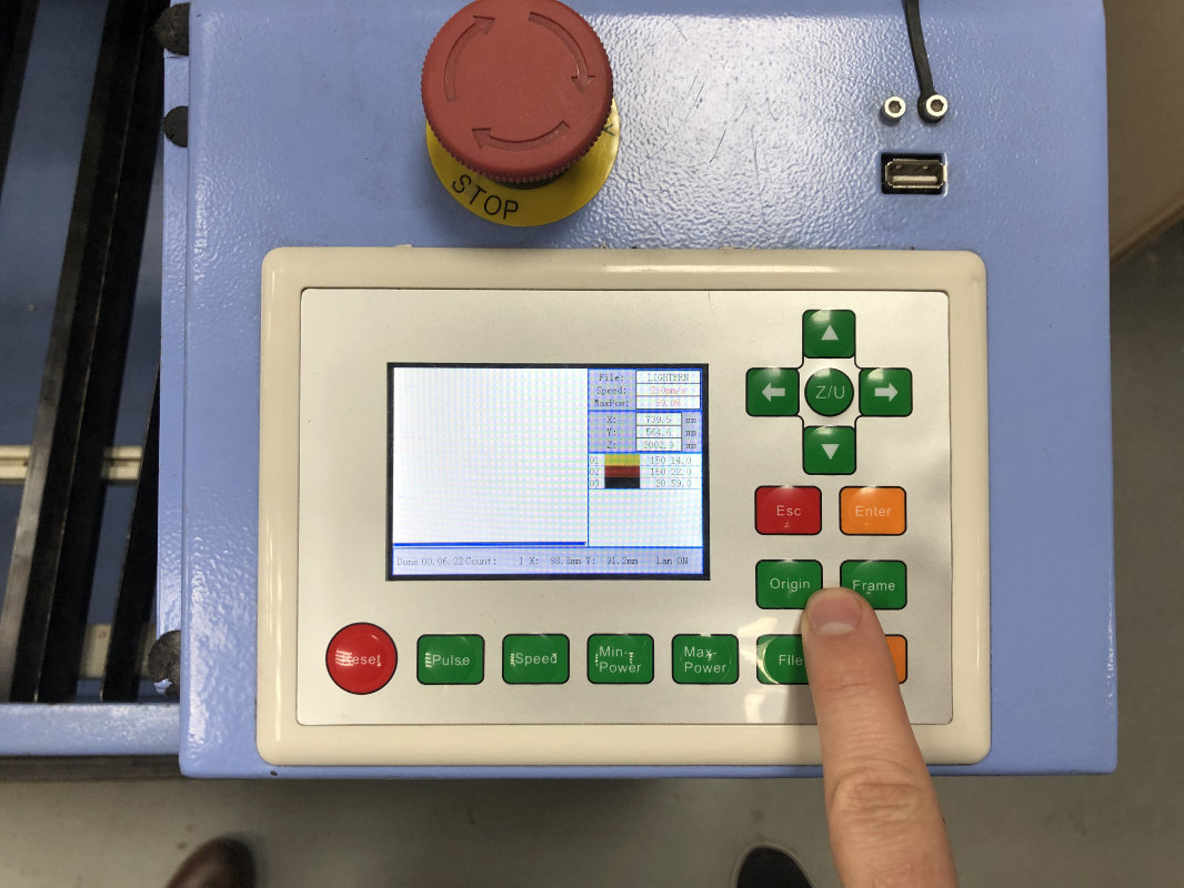
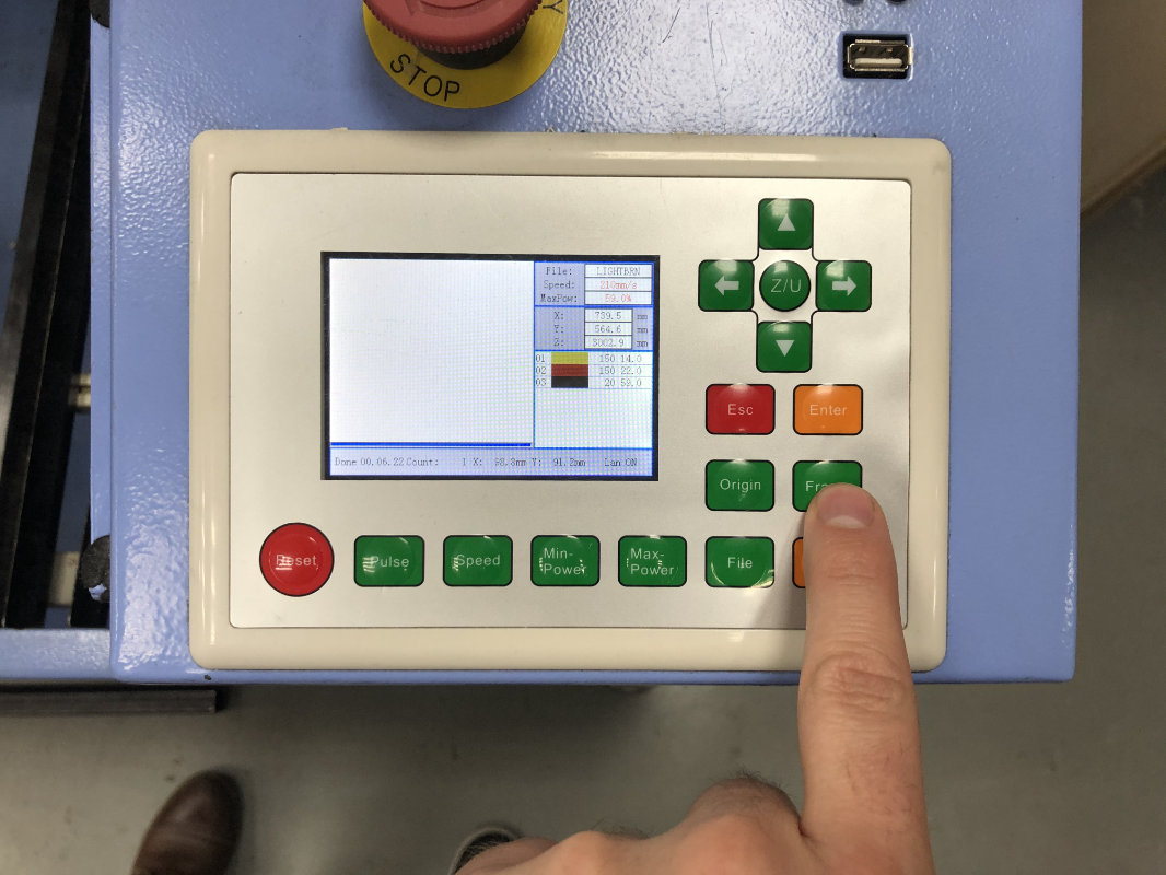
Once designed, it is time to cut out the elements on
the laser plotter.
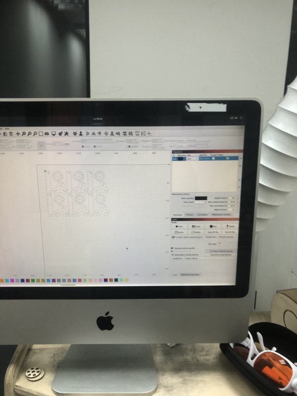
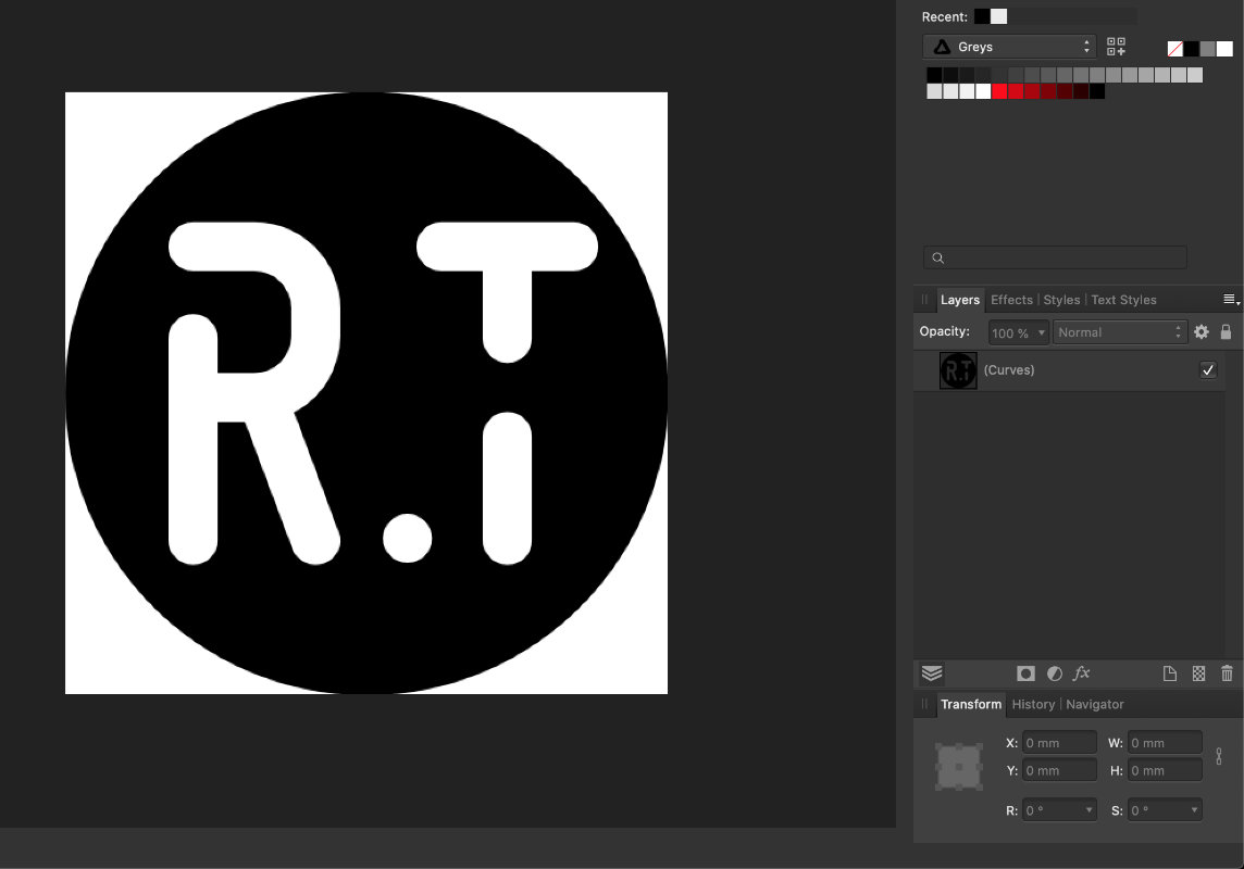
Making Project for vinyl cutter in Affinity
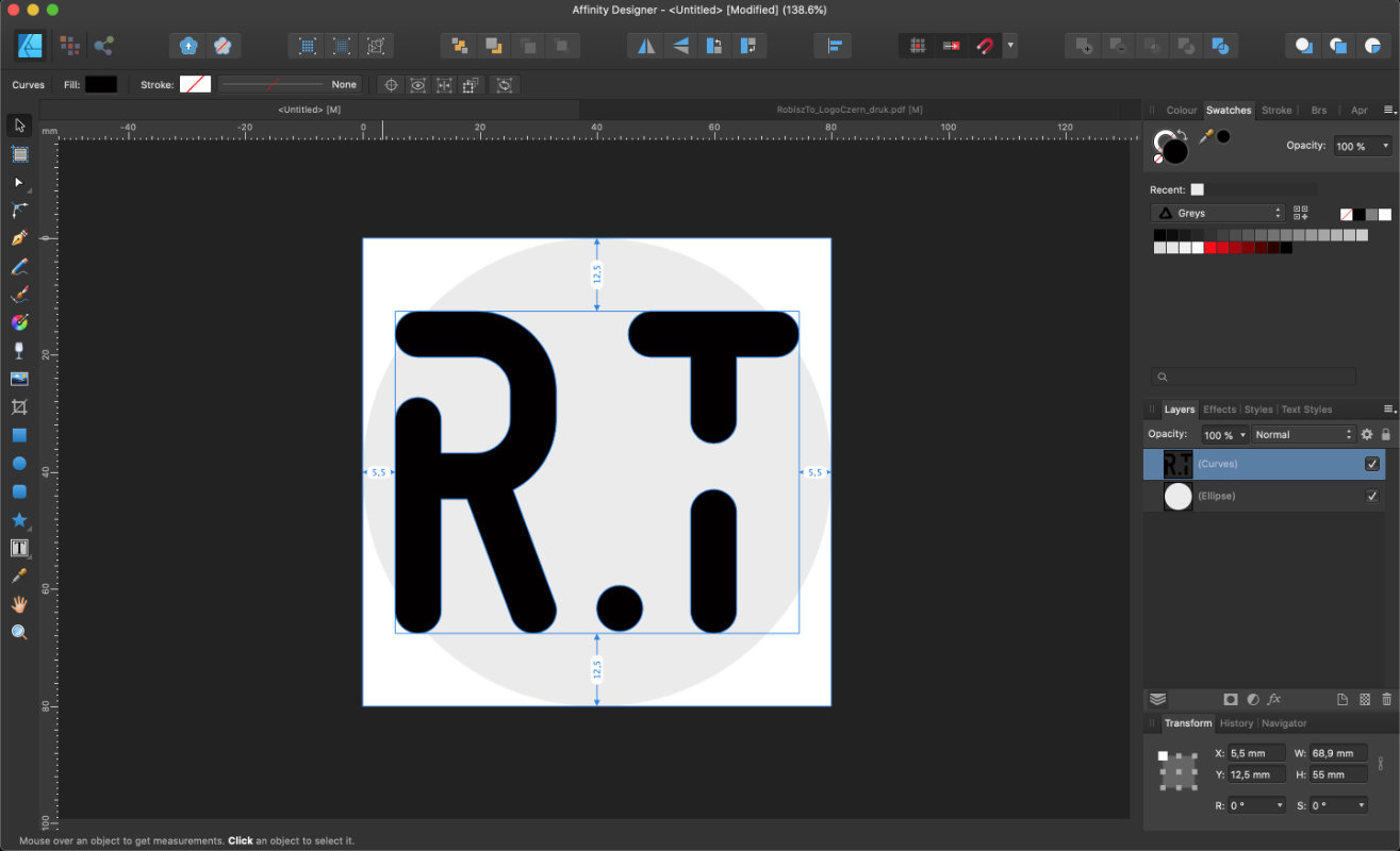
To prepare a file in vectors for vinyl cutter I used a
program which I use every day is a paid equivalent of
Adobe Illustrator, Affinity Design.
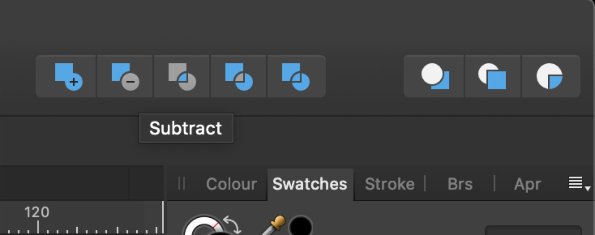
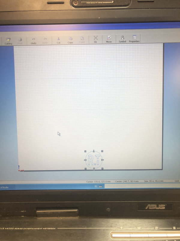
I used a ready-made Robisz.to logo and cut it out to with
the boolean option in the circle.
then I saved it in the svg. Unfortunately I needed a file
in AI so I used a free online converter.
svg to ai
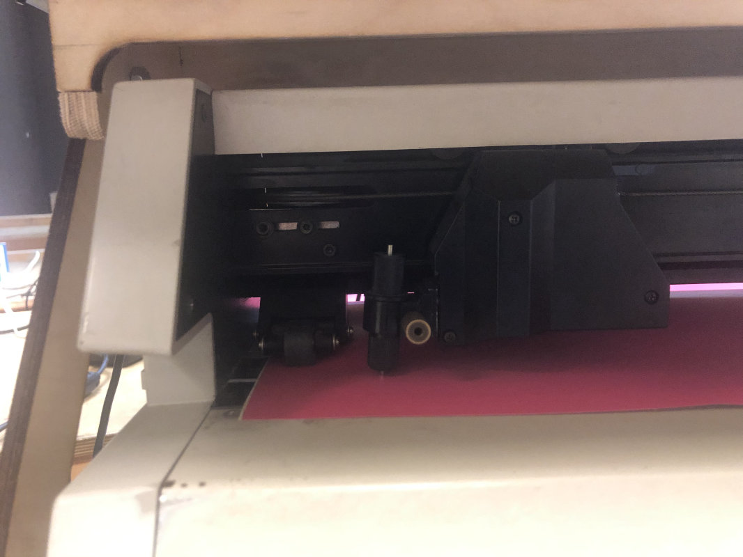
Vinyl Cutter
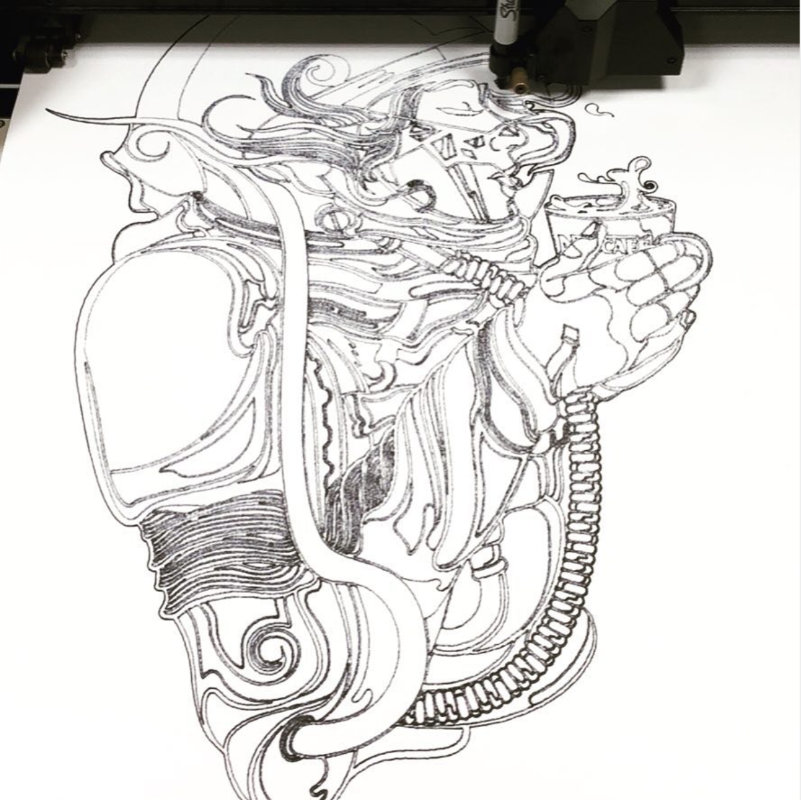
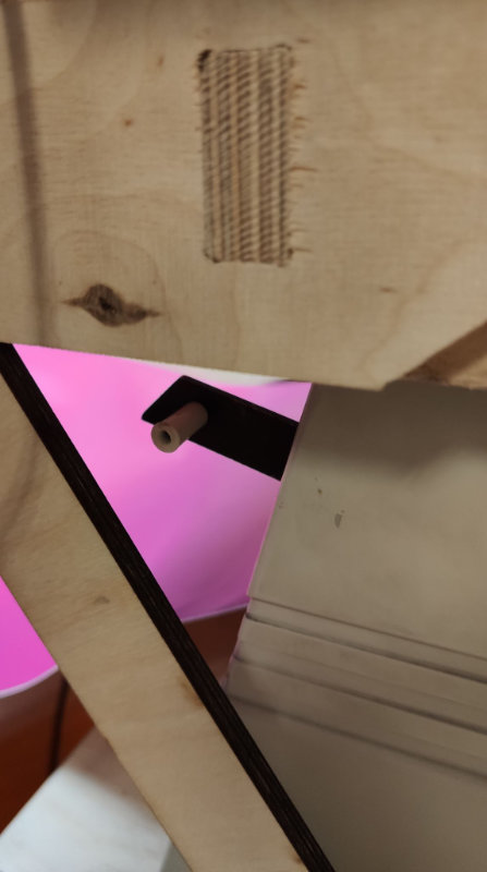
Vinyl cutter is a machine which has always fascinated me in a very fast way we can cut something in a self-adhesive foil to stick everything around:Q But... that's not all this machine can do at the beginning of my acquaintance with this machine I was playing with drawing my projects and some extra once from internet using markers on large format paper, I must admit it was a lot of fun.
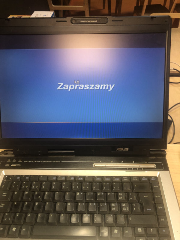
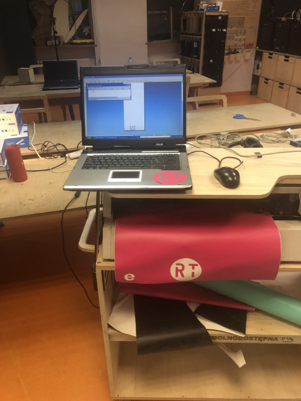
It's been a long time since we've used a vinyl cutter in fablab and it turned out that the only computer that has an LPT connector (necessary to operate this machine) was formatted and installed on it win 7. ehhh... it's not easy to be a marker. After a few moments I found a proper Linux distribution (ubuntu mate) and an interesting article how to get started with almost every vinyl cutter. To create a bootable disk for ubuntu I used Belena Etcher very simple program to flash OS to usb and SD cards.
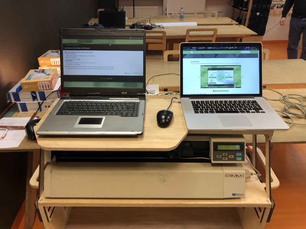
But...... after many attempts to install appropriate drivers and repositories, unfortunately I had to go back to the original windows XP, which was on that old laptop.
I will certainly try alternative options but unfortunately one week is not enough to experiment if you want to finish the task. I'll probably come back to this task and hopefully add some interesting information about Roland and linux.
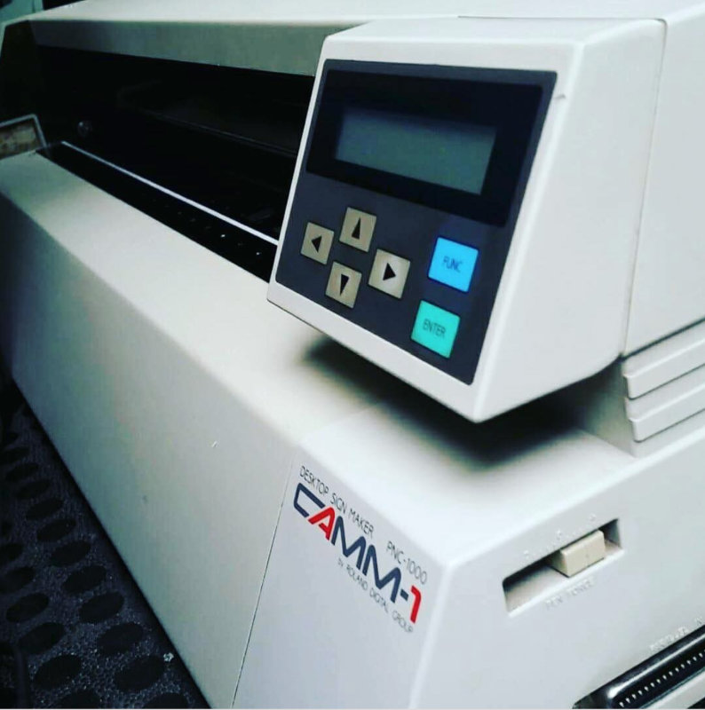
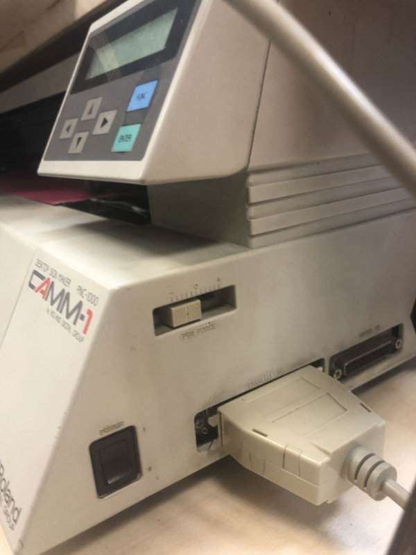
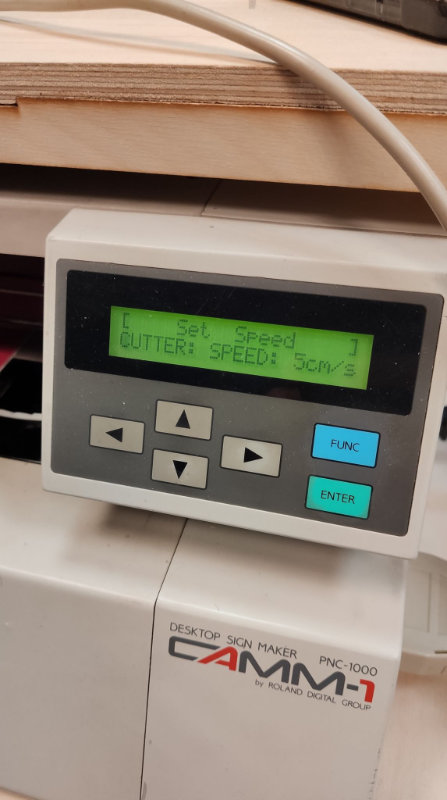
Roland CAMM-1 PNC 1000
foil transfer to objects
To transfer the cut foil intact to the surface we need the transfer foil.