
Week_14 - Networking and Communications

Assigment
Individual assignment
Group assignment:
Group assignment:
Individual assignment:
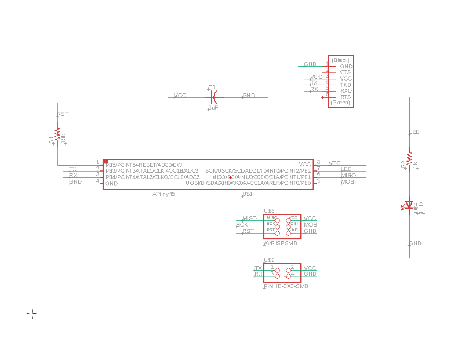
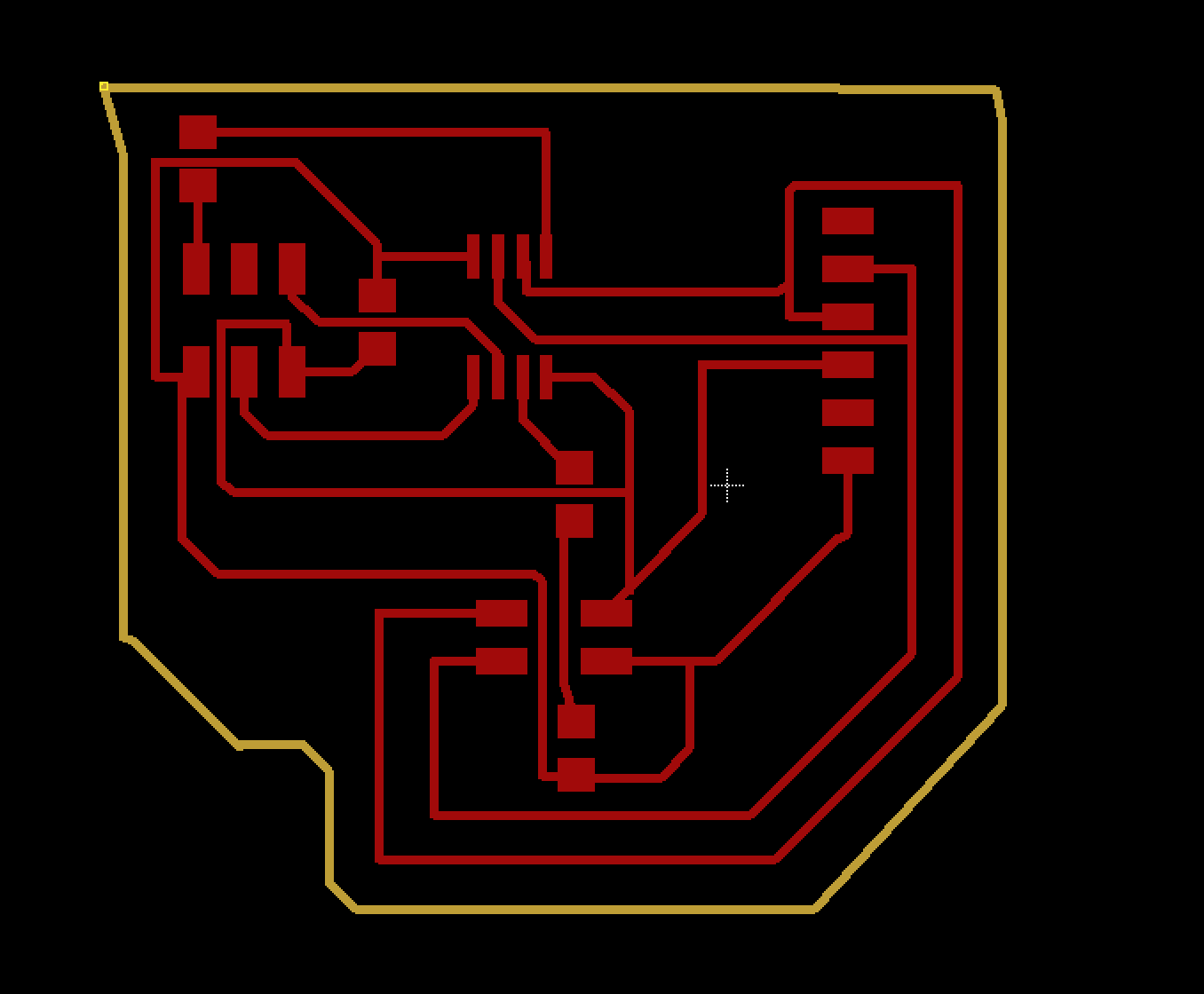
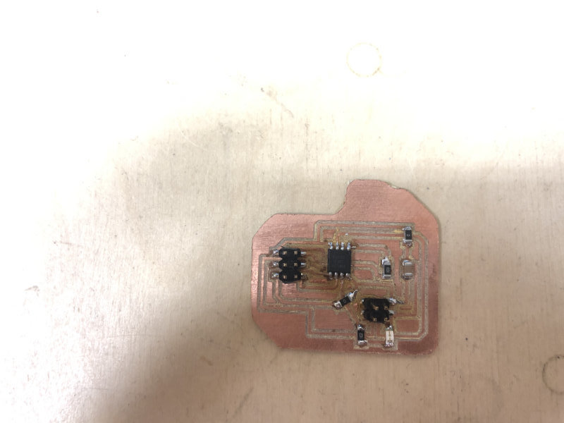
For this week i created two boards Bridge master board and node slave board. My master board simply had an ATTiny45, FTDI to comunicate with tx, rx, ground and vcc . Additionaly my board had a Pinhd-2x2 for communication with another board. Here is the board and schematic:
Bridge
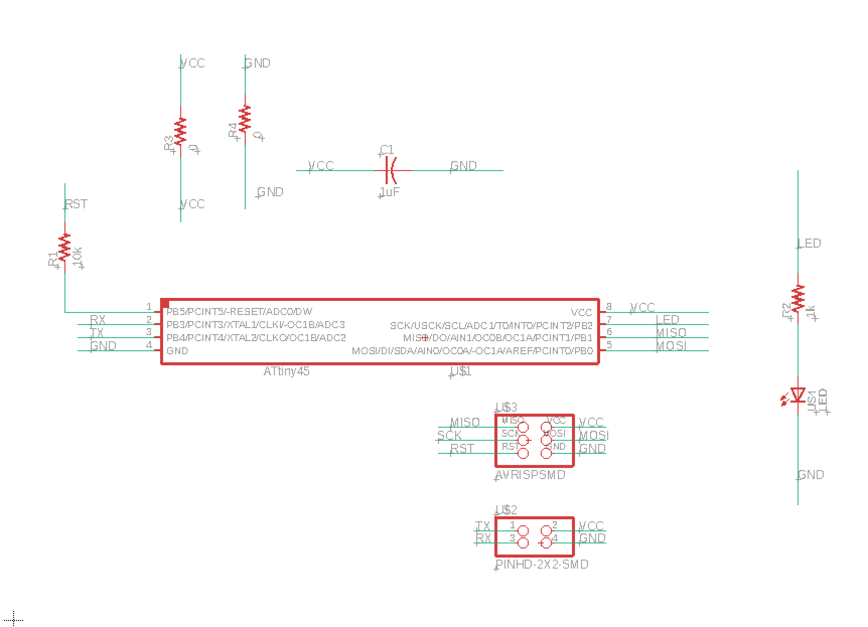
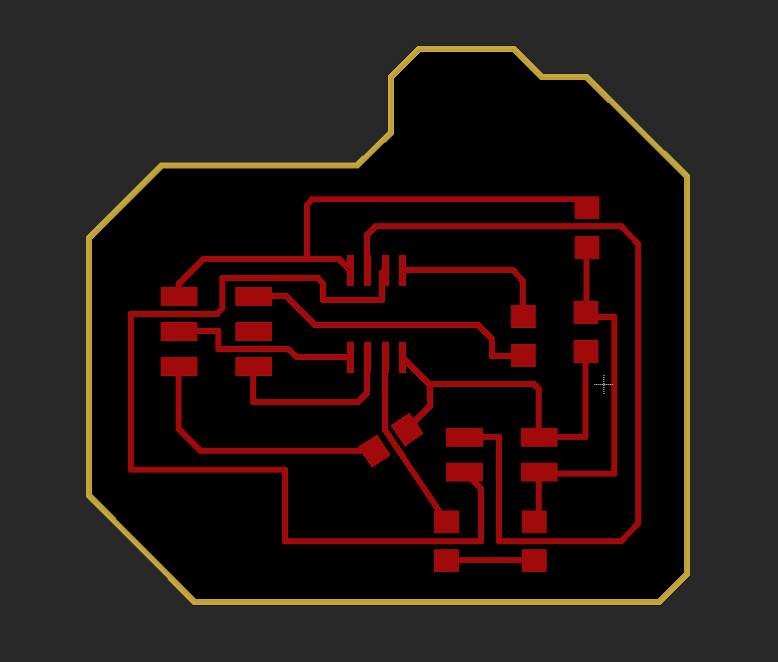
For my node board i used also ATTiny 45 and Pinhd-2x2 for communication. And ofcourse i used LED to show the resulete of the assignment.Here is the board and schematic:
Node
New Beginning: Arduino
Unfortunately, I made some mistakes while designing the pcb board and I waited for the weekend (FR1 is very difficult to get in Poland and i dont known why the shipment from Germany took more time than usual). Another problem was that the deadline was coming, which was already extended many times anyway, so I decided to do this task on arduino and possibly complete it in the future for documentation purposes and for next generations of fabacademy.Meanwhile, below I present the process I undertook while working with Arduino.
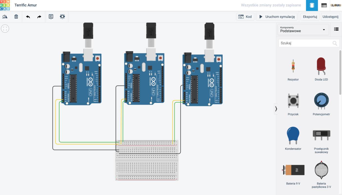
The first thing was, of course, testing the circuit in Tinkercad, which has already helped me many times this year in Fabacademy! I started with a simple circuit to see if what I know is enough to get a little bit more out of it later. That is, a simple flashing of the led on pin 13.
I put in 3 arduino and 3 breadboards. The whole system will consist of a bus and two nodes. Communication will be done using I2C protocol.
I2C (Inter-Integrated Circuit) is a serial communication protocol, so data is transferred bit by bit along a single wire (the SDA line). Like SPI, I2C is synchronous, so the output of bits is synchronized to the sampling of bits by a clock signal shared between the master and the slave. The clock signal is always controlled by the master.
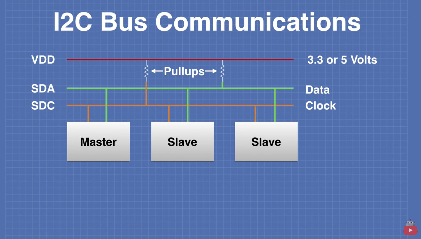
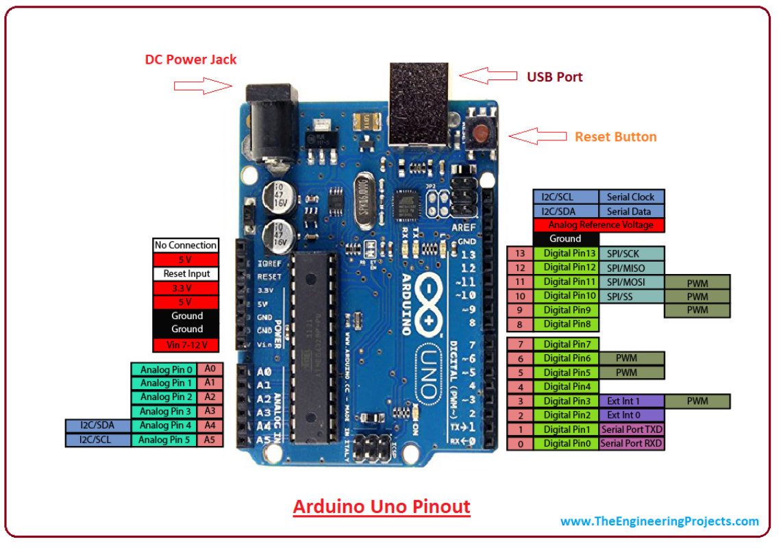
All Arduino have to be connected to common GND , SCL clock line(A5) and SDA data line (A4) (using Analog 5 and 4)It is very important to connect SCL and SDA to the appropriate pins, of course we can check everything on the appropriate diagram.
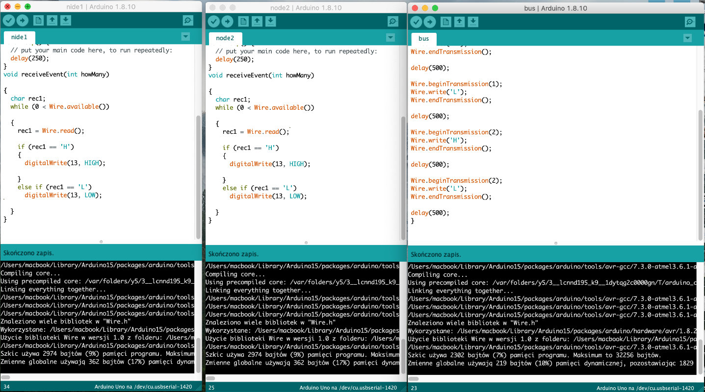
The next step was to write the code for this. I knew for sure I have to add Wire.h library, which is responsible for I2C / TWI communication:)
Then at the beginning of the program you had to call the Wire Wire.begin() library; after such a designation, we know that the arduino data will be a bus and will control the whole system by giving any number in brackets. In my case it will be 1 and 2.
Then we start the data transmission using Wire.beginTransmission(id_of_the_reciver); where we start communication with the specific device.
By starting the broadcast, you can use the Wire.write('H') function to give a high state.
Then you end the transmission with the Wire.endTransmission(id_of_the_reciver) function;
Node Code:
We need to name the reciver
Wire.begin(1);
and set it to receive status with the command
Wire.onReceive(receiveEvent);
And of course, as always when listening to
Serial.begin(9600);
We can also print out what signals the start of the program:)
Serial.println("Command me my master");
At this point we start the listening program void receiveEvent()
we give the name of the constant, which will be received from the bus in our case these are the letters, so it will be best to set the char and name it.
char rec1= Wire.read();
Of course, then type what was received
Serial.println(rec1);
Bus arduino code
		#include Wire.h>

void setup() {
  // put your setup code here, to run once:
  Wire.begin();

}

void loop() {
  // put your main code here, to run repeatedly:
Wire.beginTransmission(1);
Wire.write('H');
Wire.endTransmission();

delay(500);

Wire.beginTransmission(1);
Wire.write('L');
Wire.endTransmission();

delay(500);

Wire.beginTransmission(2);
Wire.write('H');
Wire.endTransmission();

delay(500);

Wire.beginTransmission(2);
Wire.write('L');
Wire.endTransmission();

delay(500);
}
Node Code
		#include Wire.h>

void setup() {
  // put your setup code here, to run once:
  Wire.begin(1);
  Wire.onReceive(receiveEvent);

  pinMode (13, OUTPUT);
  digitalWrite (13, LOW);

  Serial.begin (9600);
}

void loop() {
  // put your main code here, to run repeatedly:
  delay(250);
}
void receiveEvent(int howMany)

{
  char rec1;
  while (0 < Wire.available())

  {
    rec1 = Wire.read();

    if (rec1 == 'H')
    {
      digitalWrite(13, HIGH);

    }
    else if (rec1 == 'L')
      digitalWrite(13, LOW);

  }
}
TEST
After a successful attempt I decided to build a system in which the bus reads data from the potentiometer and because of the reading it turns on either the led on arduino number 2 or 3. needed components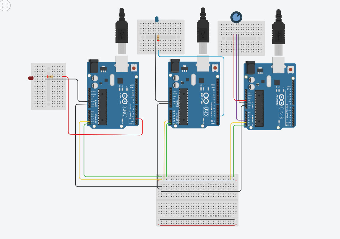
Arduino are connected to each other as in the previous example, i.e. they share GND, SLC and SDA. Additionally, the two nodes are connected to the leds one to pin 3 and the other to pin 2.
Bus code
#include  Wire.h>
int analogPin = 3; //alalog pin setup
int inputValue= 0; // value

void setup() {
  // put your setup code here, to run once:
  Wire.begin();
 Serial.begin(9600);
}

void loop() {

inputValue=map(analogRead(analogPin),0,1023,255,1); //maping the range

Wire.beginTransmission(1);
Wire.write(inputValue);
Wire.endTransmission();

delay(500);

Wire.beginTransmission(2);
Wire.write(inputValue);
Wire.endTransmission();

delay(500);

}
node1
		#include Wire.h>
int rec1;
void setup() {
  Wire.begin(1);
  Wire.onReceive(receiveEvent);
  pinMode (3, OUTPUT);
  digitalWrite (3, LOW);

  Serial.begin (9600);
}

void loop()
{
  // put your main code here, to run repeatedly:
  delay(250);
}
void receiveEvent(int howMany)

{
  rec1 = Wire.read();
  Serial.println(rec1);


  if (rec1 > 100)
  {
    digitalWrite(3, HIGH);

  }
  else if (rec1 < 100)
    digitalWrite(3, LOW);

}
		#include  Wire.h>
int rec1;
void setup() {
  Wire.begin(2);
  Wire.onReceive(receiveEvent);
  pinMode (2, OUTPUT);
  digitalWrite (2, LOW);

  Serial.begin (9600);
}

void loop()
{
  // put your main code here, to run repeatedly:
  delay(250);
}
void receiveEvent(int howMany)

{
  rec1 = Wire.read();
  Serial.println(rec1);


  if (rec1 < 100)
  {
    digitalWrite(2, HIGH);

  }
  else if (rec1 > 100)
    digitalWrite(2, LOW);

}
Arduino Networking
Group Assigment
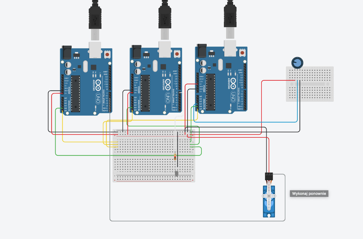
The group task this week was to connect two projects so that they could communicate with each other.My project was a modified individual project.
Project structure:
The bus sends a potentiometer value message to Node1.
Node1 lights up the led if the value is above 100
and also sends a message to the bus in the form of a "fire" phrase.
The bus receives this information and sends a message '1' to Node2
Node2 is changing the position of the motor servo to 180.
If the value on the potentiometer is below 100,
Node1 does not light up the LED
and sends a "nooo" phrase that is not "fire",
so the bus sends a 0 statement to Node2,
which means a shift to position 0 of the servo.
The new function that was used was Wire.onRequest();
Register a function to be called when a master requests data from this slave device.
What will be needed:
diagram below:
Bus code
#include Wire.h>
#define answersize 4

int analogPin = 3; //alalog pin setup
int inputValue= 0; // value

void setup() {
  // put your setup code here, to run once:
  Wire.begin();
 Serial.begin(9600);
}

void loop() {

inputValue=map(analogRead(analogPin),0,1023,255,1); //maping the range

Wire.beginTransmission(1);
Wire.write(inputValue);
Wire.endTransmission();
Serial.println("Turn on the servo");
Wire.requestFrom(1,answersize);

String response="";
while (Wire.available()){
  char b= Wire.read();
  response +=b;
}
  Serial.println(response);
  if (response == "fire"){

Wire.beginTransmission(2);
Wire.write(1);
Wire.endTransmission();
  }
  else
  {
  Wire.beginTransmission(2);
Wire.write(0);
Wire.endTransmission();

  }
  delay(500);
}
Node1 Code
#include Wire.h>
#define answersize 4
String answer="fire";
String answer1="nooo";
int rec1;
void setup() {
  Wire.begin(1);
  Wire.onRequest(requestEvent);
  Wire.onReceive(receiveEvent);
  pinMode (7, OUTPUT);
  digitalWrite (7, LOW);

  Serial.begin (9600);
}

void receiveEvent(int howMany)

{
  while (0 100)
  {
    digitalWrite(7, HIGH);

  }
  else if (rec1 < 100)
    digitalWrite(7, LOW);
  }

  }

  void requestEvent()
  {
    byte response[answersize];

    if (rec1 > 100)
  {

    for (byte i=0; ianswersize;i++)
{
      response[i] = (byte)answer1.charAt(i);
    }
    Wire.write(response,sizeof(response));

    }


    void loop()
    {
      delay(500);
      }
Node2 Code-with servomotor
			#include
#include
Servo servo1;
int move_servo;
int servo=5;
void setup() {
  Wire.begin(2);
  Wire.onReceive(receiveEvent);
  Serial.begin (9600);
   servo1.attach(servo);
}

void loop()
{
  // put your main code here, to run repeatedly:
  delay(250);
}
void receiveEvent(int howMany)

{
  move_servo = Wire.read();
  Serial.println(move_servo);


  if (move_servo == 1)
  {
    servo1.write(180);

  }
  else if (move_servo == 0)
    servo1.write(0);

}
Simulation in tinkercad
Arduino Video