Tieing up loose ends for the 3D printing week.
During my original week I managed to explore various scanning techniques and went through basic printing shape limitations.
What I thought I could focus on this week is to explore more sophisticated means of scanning and printing. It is ironic that exactly this week I had both another MRI and a dental 3D-scan.
Inspiration
Exactly this week in IAAC there were presentations of Master program specializing in Clay 3D printing. This was a huge inspiration for the topic:
.jpg) – IAAC OTF presentations –
– IAAC OTF presentations –
.jpg)
.jpg)
.jpg)
.jpg) – IAAC OTF Results –
– IAAC OTF Results –
MRI
It just so happened that exactly this week I had to do MRI.
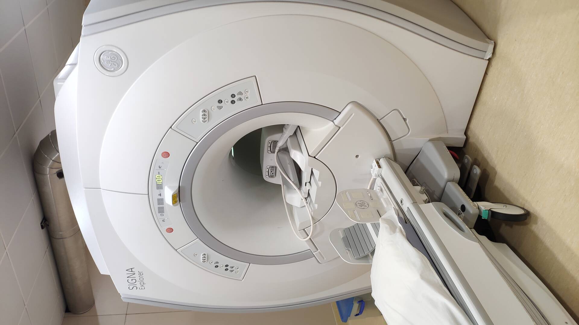 – MRI machine –
It would still be a while till I manage to get the scans. So for now I continue with the previous scans I had.
Mesh resulting from slicing the scan was barely usable: extremely heavy mesh is hard to open not to mention do anything with it.
My first approach was to through as many smart algorithms to clean it up. However, mesh resolution is extremely high but scanning not as much. This result in very detailed mesh with a lot of noise that is hard to discard since it spans multiple local features. After using standalone tools like Meshroom as discribed in last post on the topic, I turned to something I was a bit more comfortable with - Rhino7. While it might not be optimized for the task it gives you opportunity to manipulate mesh in a very broad spectrum of ways.
– TODO: screenshot of input mesh – – TODO: screenshot of input mesh –
One thing I tried to use was Rhno7’snew geometry type - SubD - a format that is a vector representation of geometry but designed to include topology-centric features of mesh type. I followed these tutorials to learn about this new feature: TODO: put links.
Being vector type it can codify complicated geometry with way less data-density than a mesh thus making it more manageable. Some abstraction is obviously to be done, but ultimately this is happening anyway when we’re talking about 3d scanning.
Converting directly to SubD did not result in usable results if managed to complete at all. Using a “Quad Remesh” tool that analyzes the topology and simplifies surface into better suited for SubD quad elements - I started to get some results. But either due to my computer being not apt for job or potential bugginess of the new feature, the process was getting stuck in what seems like a loop for days with no visible progress. I tried remeshing the scan to reduce resolution - before the command, but since it is fairly low level algorithm it did not preserve enough details.
– TODO: screenshot of loop –
This was clearly not enough to reduce complexity so What I thought I could try is to run this on a smaller portion of the scan. Using “Trim Mesh” I narrowed the scan down to a slice.
– TODO: screenshot of slice of MRI mesh –
What I thought I could try with the slice is to treat the surfaces as separators for solid volumes, thus get some sense of the volumetric composition of the insane geometry in the scan. For this I turned to Grasshopper.
TODO: The script is still in progress
Dental
Dental scan however turned out to be way easier to manage, cause their scanning software is capable of producing an [.stl] directly, which made it way more usable.
To go from a surface to a printable geometry I did relatively crude processing in Grasshopper: I extracted naked edges of the mesh which I then rebuilt with a height on the bottom bounds of the scan with some offset - that I could use to generate projected loop that can be lofted back to the original and stiched up. This however introduces various self intersections since the original loop is in 3D and is fairly windy. I found that by actually pushing the points down instead of lofting additional sides I could significantly reduce open wholes I was getting after closing the mesh. Also default component to extract naked vertices was not behaving as expected so I extracted Naked edges and got point from there, which I then found back in the list of points in mesh deconstruction.
– TODO: Dental print: screenshot –
Ultimately cleaning it up as much as I could using very handy Mesh Repair tool in Rhino. I passed it to BCN Cura slicer to confirm it can manage it.
At the moment lab has offloaded many printers for an external event. So I only had Sigma at my disposition. Of the broad library of leftover fillaments in the lab I picked something that should suit printing fake teeth the most :) - semi-transparent HIPS based [TODO Find material name]. After going through [the documentation] on the material - I found that I should set the bed to heat up to 60 degrees, heat extruder to 215. I set the resolution to be .1 mm, infill [TODO name] and added [breem TODO: confirm].
– TODO: Material picture –
.jpg) – Material Loaded –
– Material Loaded –
.jpg) – Sigma Printer –
– Sigma Printer –
.jpg) – Print Settings –
– Print Settings –
.jpg)
.jpg)
.jpg)
.jpg) – Dental print process –
– Dental print process –
The result was impressive and having a look from outside I noticed things I never really payed attention to.
.jpg)
.jpg)
.jpg)
.jpg) – Dental Print Details –
– Dental Print Details –
.jpg)
.jpg) – Dental Print Results –
– Dental Print Results –
There were a couple of problems with the print:
- Print has partially lifted off the bed. From reading about the issue I found that this is most likely cause: since the room in which the printer is not well conditioned, air temperature varies a lot between day and night, which in turn changes print conditions. The solution should be to close off the print chamber and to more steadily control air conditions in the lab while printing.
.jpg)
.jpg) – Partial lift off from the bed –
– Partial lift off from the bed –
- Print had small artifacts on the surface. At first I thought it could have been dur to imperfections in scan, but some research into the matter showed it could have been cause by a problem with retraction settings for the material.
.jpg) – TODO: surface artefacts –
– TODO: surface artefacts –