First attempts on fabrication of CNC-cut custom circuits.
theory
// TODO: transfer some data from conspects
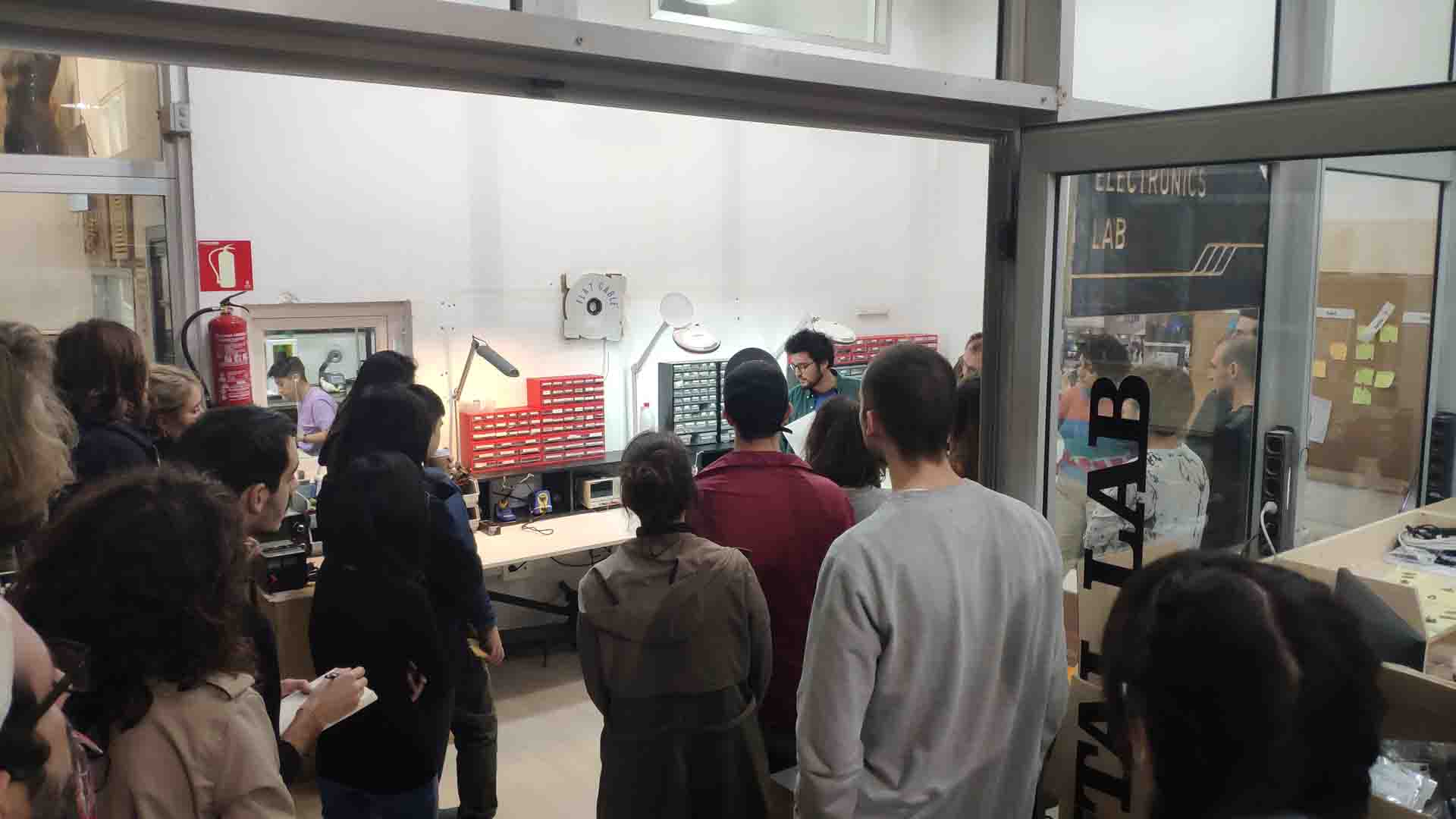 – Presentation of Electronics Lab –
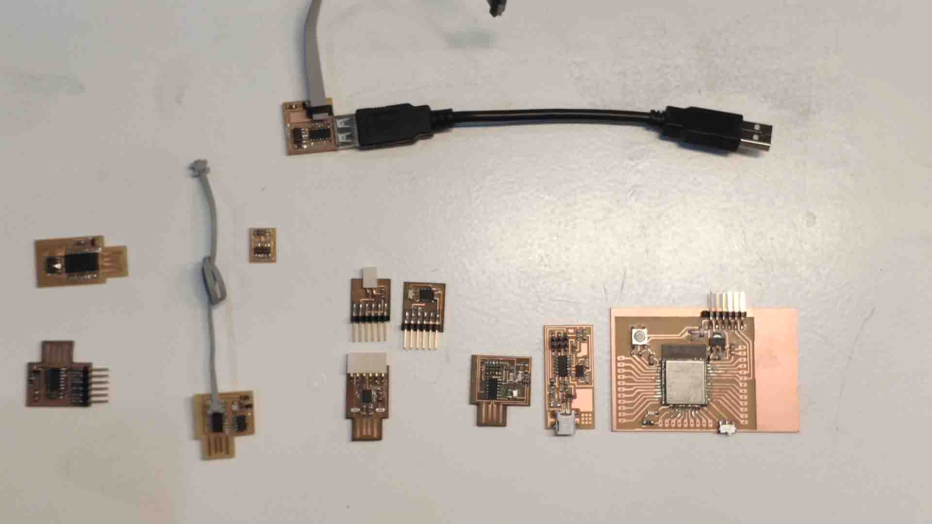 – Examples of Custom PCBs –
personal conclusions
The biggest revelation for me was the accessibility and relative ease of fabricating of a custom board. Out world today is so interwoven with the electronics at any field at any function. The further we go the more layers of abstraction we introduce. Most often this results in the isolation of hardware, low-level, logics and generalization of technical concepts into increasingly simple form. Coding is a good example - from direct 1s and 0s, to assembler, to human language-like coding languages, to huge libraries and even more powerful tools. However, there is another way, way of actually democratizing details, and decentralizing knowledge to a community - a very close logic to FabAcademy ideology. In this framework making a PCB is not an unnecessary complication requiring extreme quantities of experience and highly specific knowledge, but a tool, like any other there to be used when the task matches, While the process is indeed full of jargon and new concepts it is true testament to the framework that in two days from introduction to it I managed to cut my first board!
reality
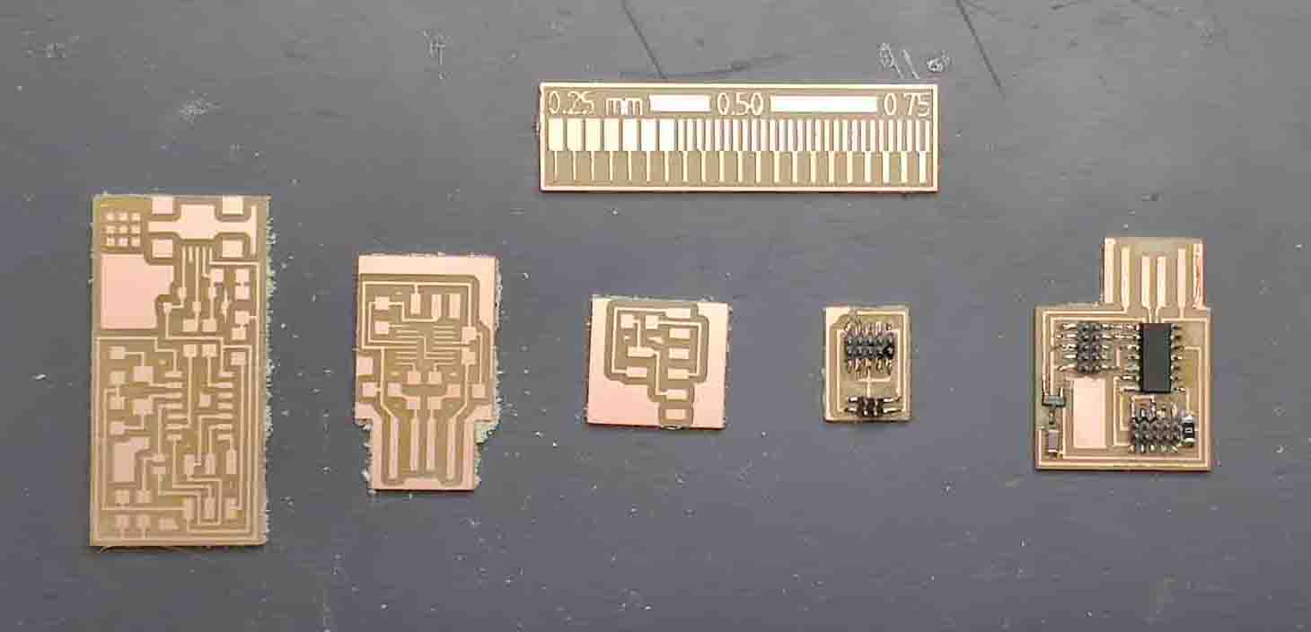
testing the limits
To start the week I decided to generate a small Grasshopper Script that generates a test file - a set of grooves and stand-alone lines to see how big (or rather small) a geometry can be made through this tool - both to fix conclusion of mine with the imperial measurement system and to be able to have it as a practice for generation of PCBs for future. Testing both machine and bit capabilities revealed that Roland SDM-20 with 1/64 inch bit can basically handle without problem lines of 0.25 mm and potentially less, but cannot make cuts less than 0,4 mm. This became obvious when I visualized the bit sizes next to the pattern and saw that 1/64’ bit is approximately 0,4 mm.
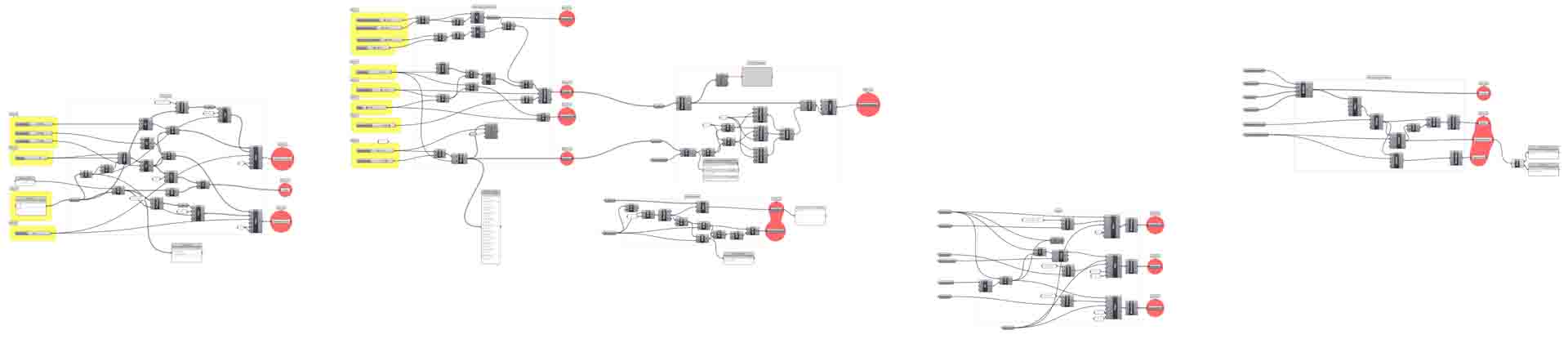 – Grasshopper Definition to Create Test File –
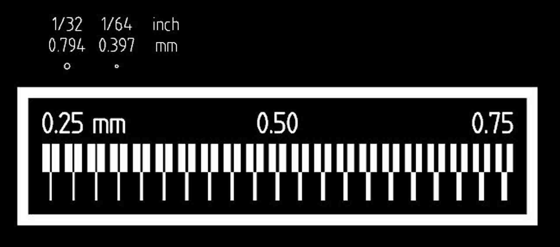 – An image for scale of Bits compared to the Test –
 – Test File in millimeters: Traces –
 – Test File in millimeters: Outline –
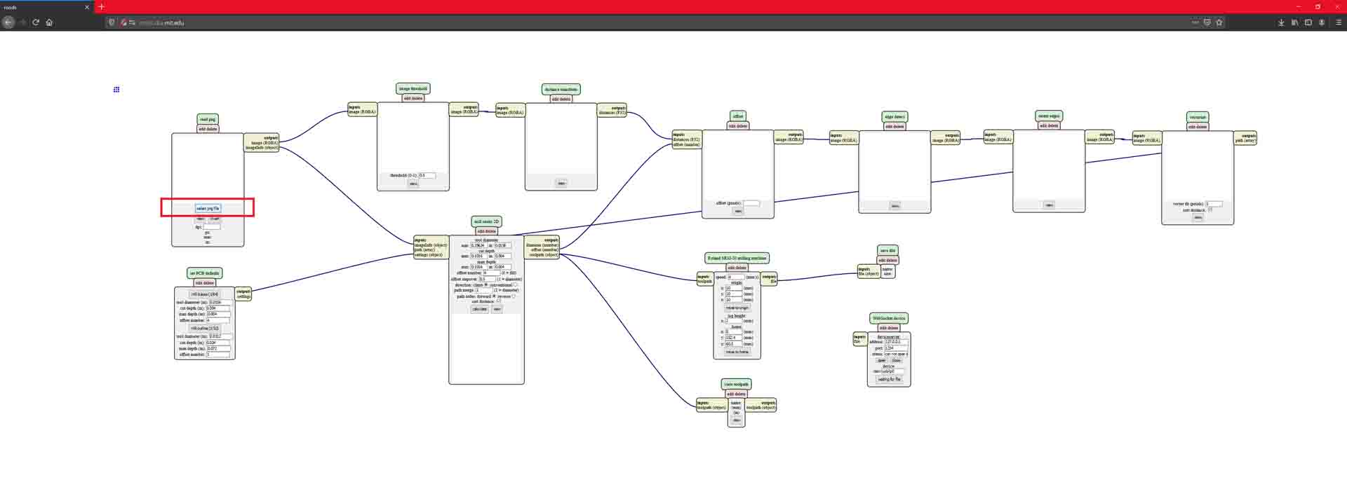
modifying the Mods
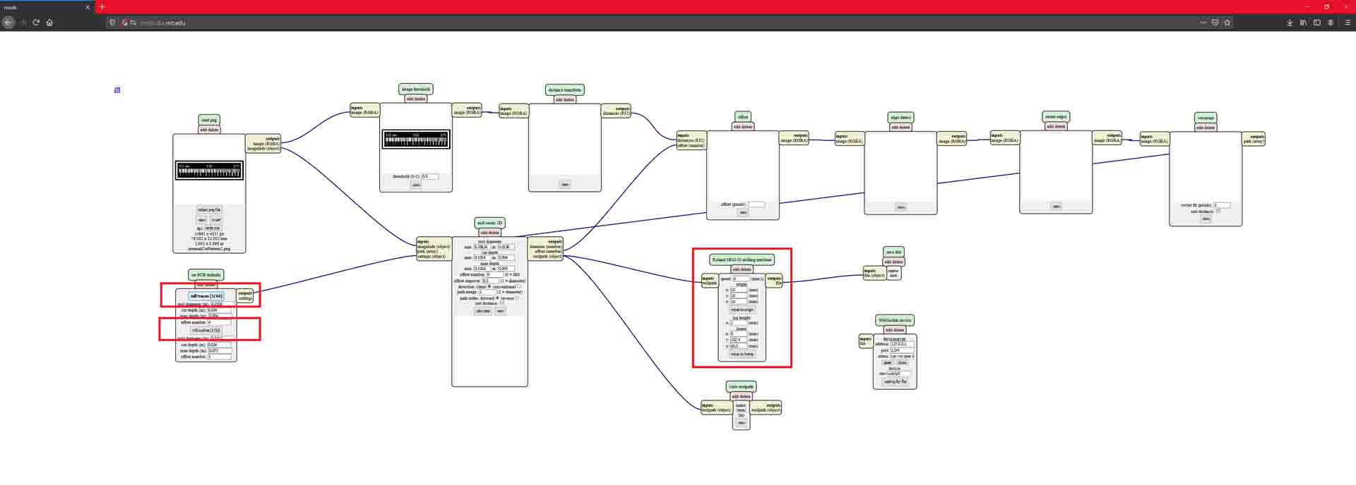
Next step in the process is to convert the design into a path for the machine to fabricate it. Following the guides of FabAcademy tutorials I first loaded a program used by default on server. To better understand what is happening inside I organized it so the tangled mess of wires is not cross referencing (famous in Grasshopper environment as Spaghetti) and applying local changes - adding two machines (to choose on the go if one or the other is busy), and adding file saving mod instead of web-interface.
 – Cleaned and Organized Mods for Fabrication in FabLab Barcelona –
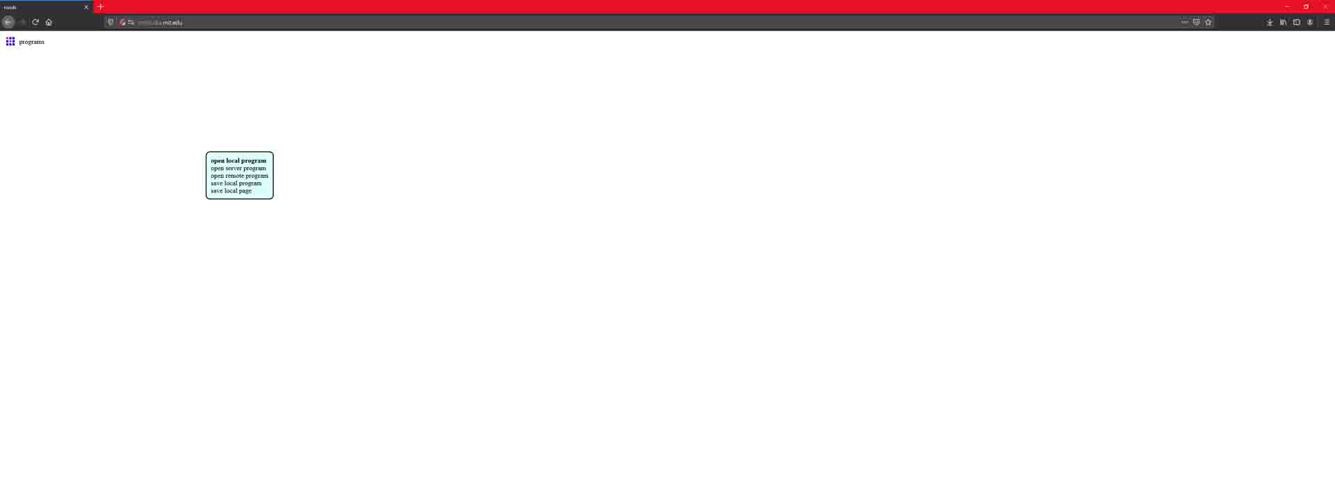
Following set of images shows step by step process of generating a file:
 – Step 1: open Mods –
 – Step 2: Right click to open program –
 – Step 3: select program type –
 – Step 4: Select program (in this case local) –
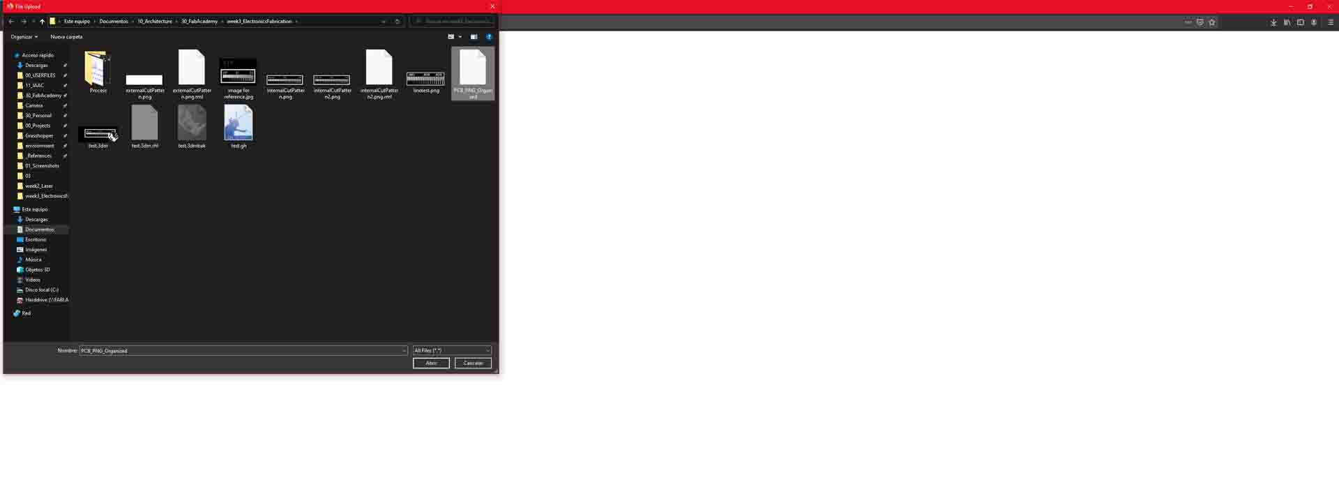
 – Step 5: Load a PNG to prepare from –
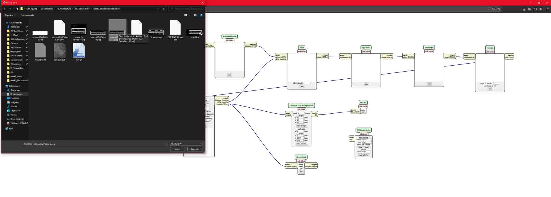 – Step 6: Select PNG image –

 – Step 7: Select Type of Milling, Set Machine Settings –
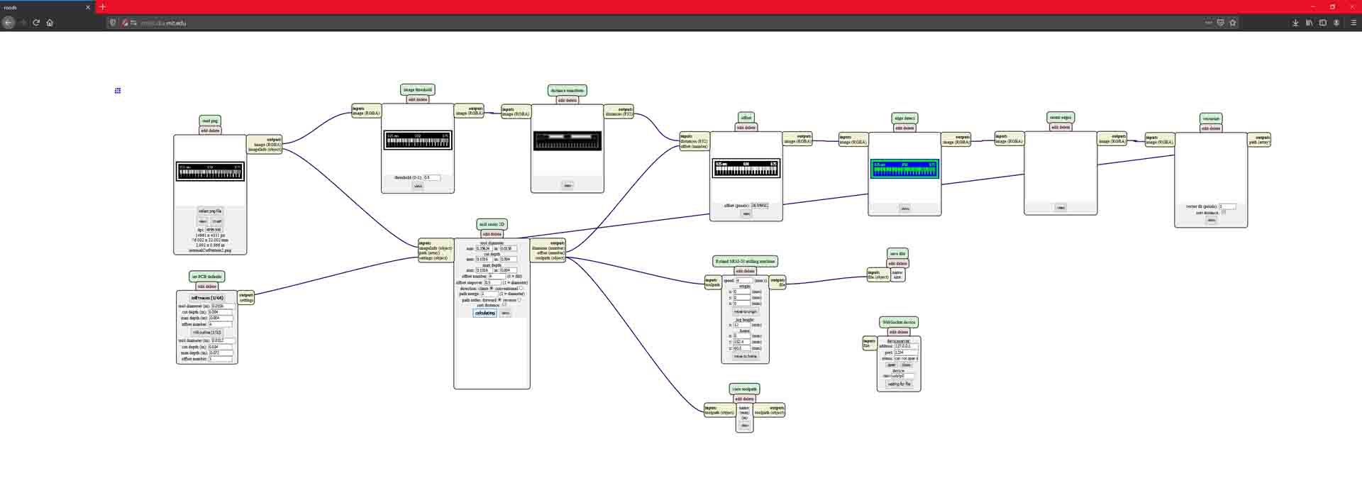
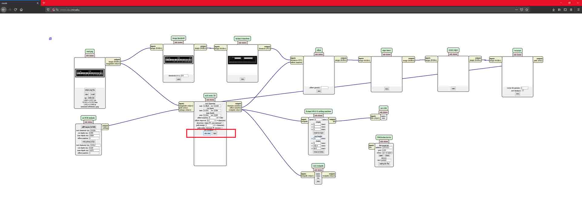 – Step 8: Calculate the path –
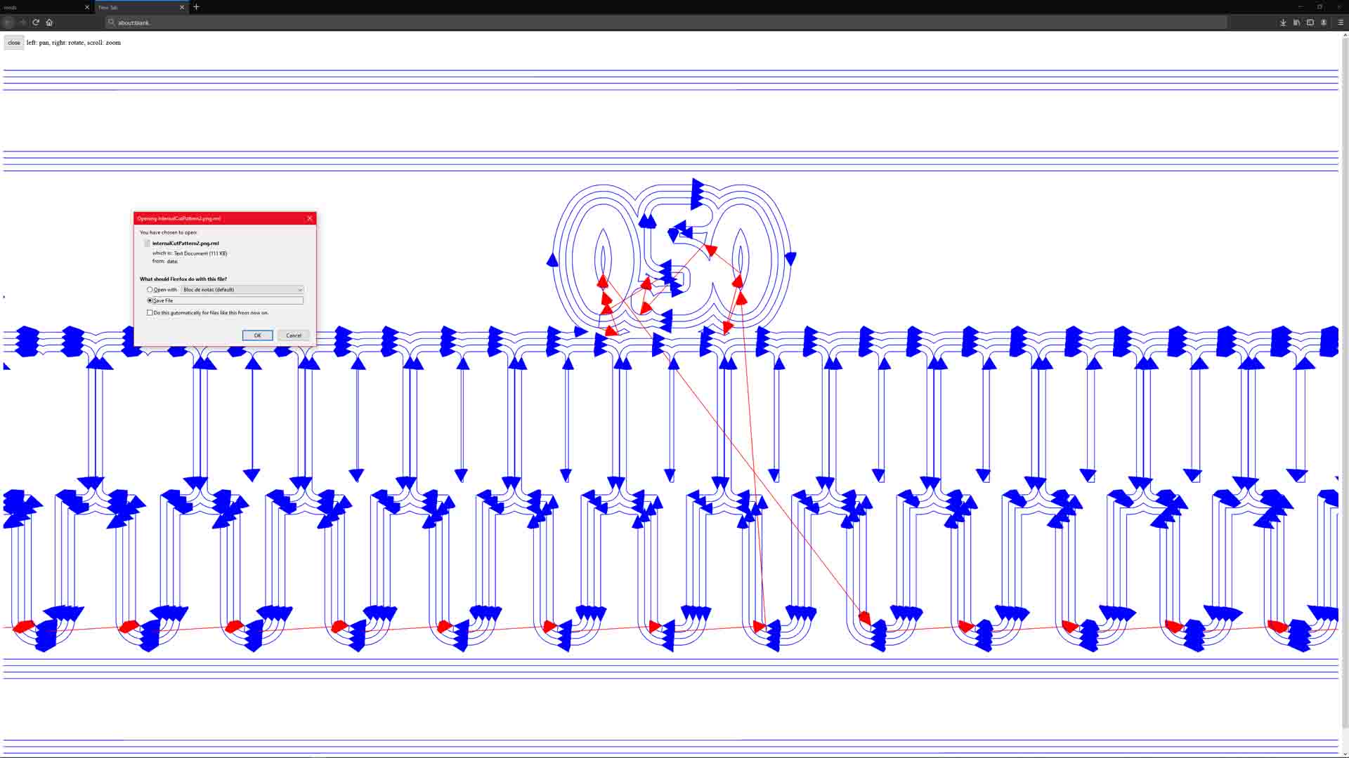 – Step 9: Check Path and Save File –
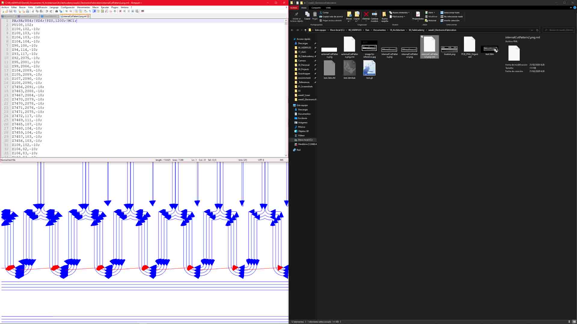 – RML File Contents –
applying the knowledge
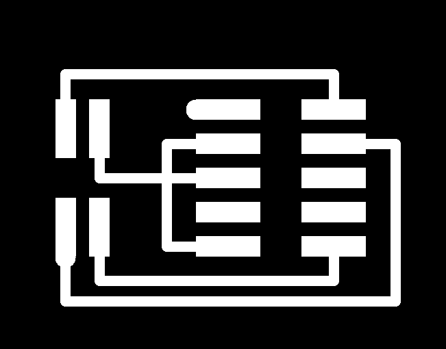
To further practice the process I gathered all the circuit programmers referenced in the program and developed RML files for all of them for both machines. As an example I show here the traces for the board we agreed in group I would have to do so we have at least one of each of them.
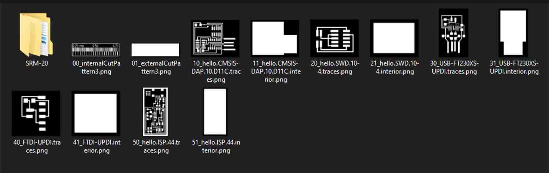 – Collected Files for Fabrication –
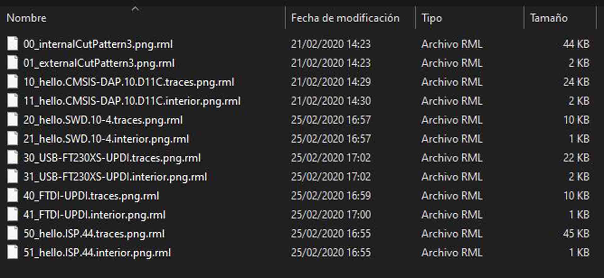 – Generated Files to Cut on SRM-20 –
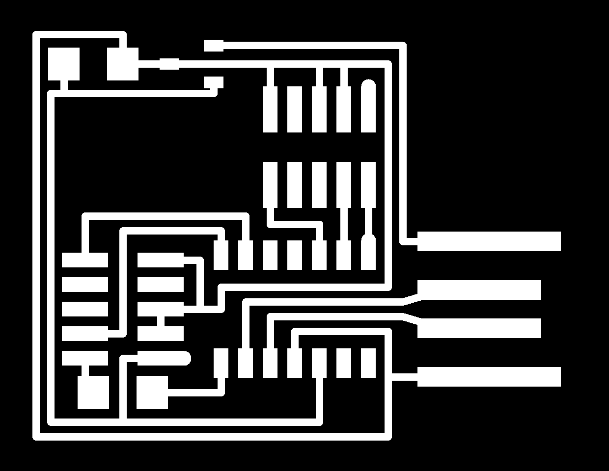 – CMSIS: traces –
 – CMSIS: outline –
 – SWD: traces –
 – SWD: outline –
the moment of truth
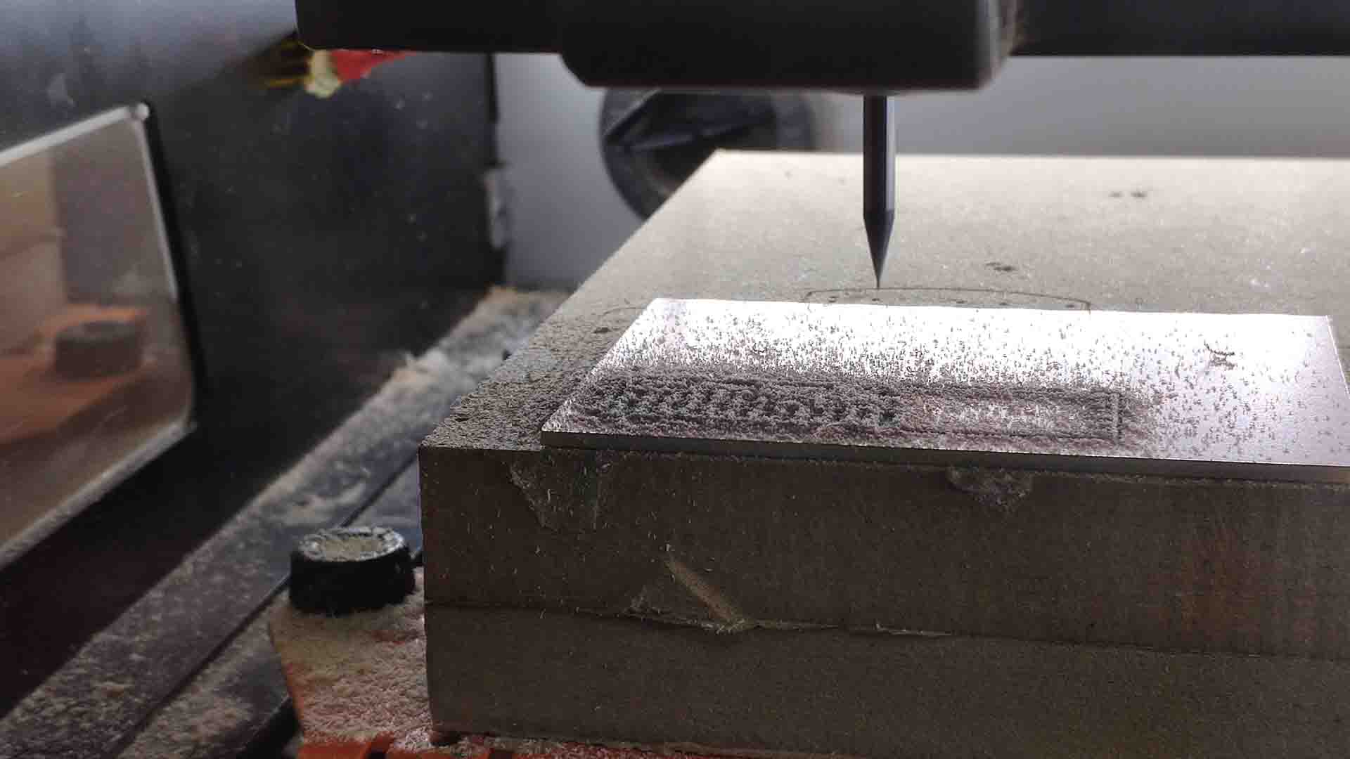
It is curiously nerve-racking to see such a tiny piece of metal touch the material for the first time and than the difficult (TODO: CONTINUE)
After successfully making a test but with a small miscalculation with the offsets (third board went too close to the first and was cut through on the cutting of the outlines) - I had to split them and pass the rest into two separate jobs for the small boards that we have to fabricate on.
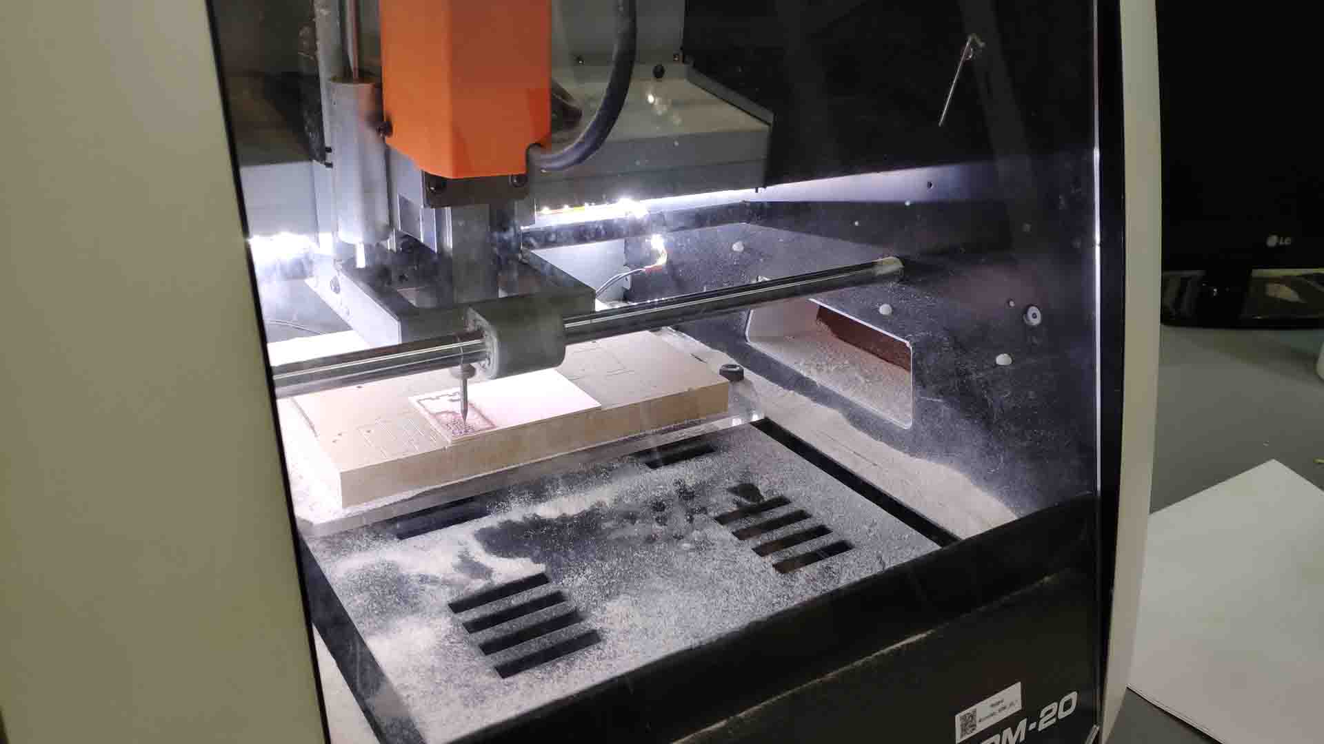 – PCB CNC Setup –
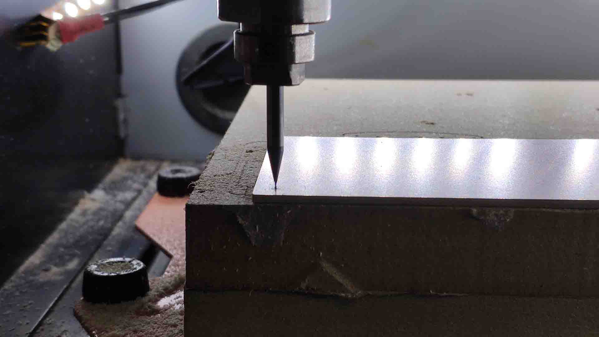 – First Contact of 1/64’ bit –
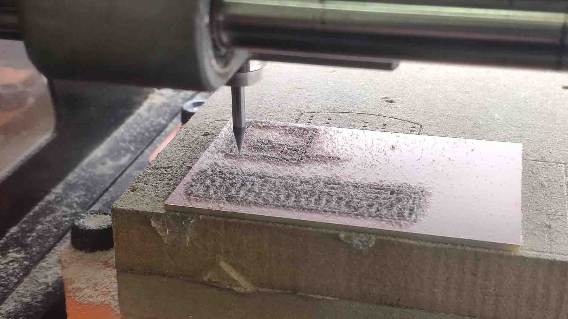
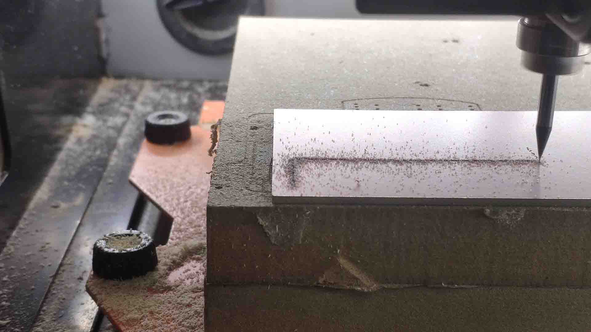 – First Cut Line –
 – Cut –
 – Nesting in one go multiple PCBs –
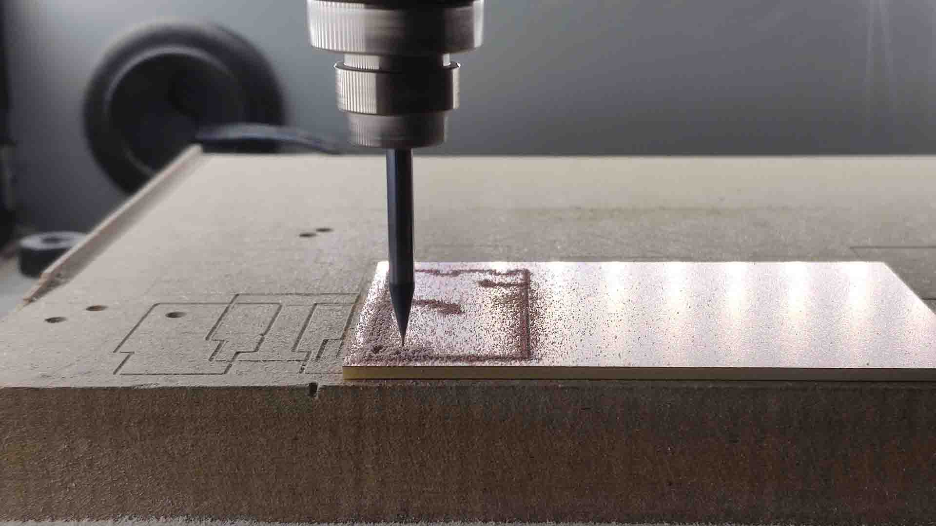 – Cut –
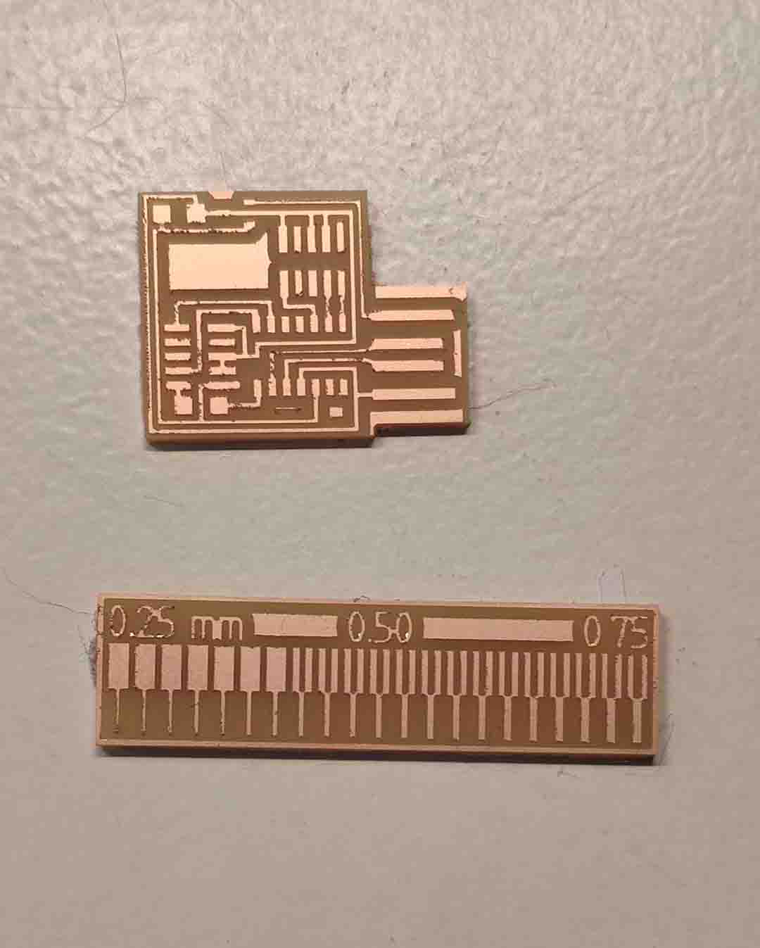 – First Cut Results –
//
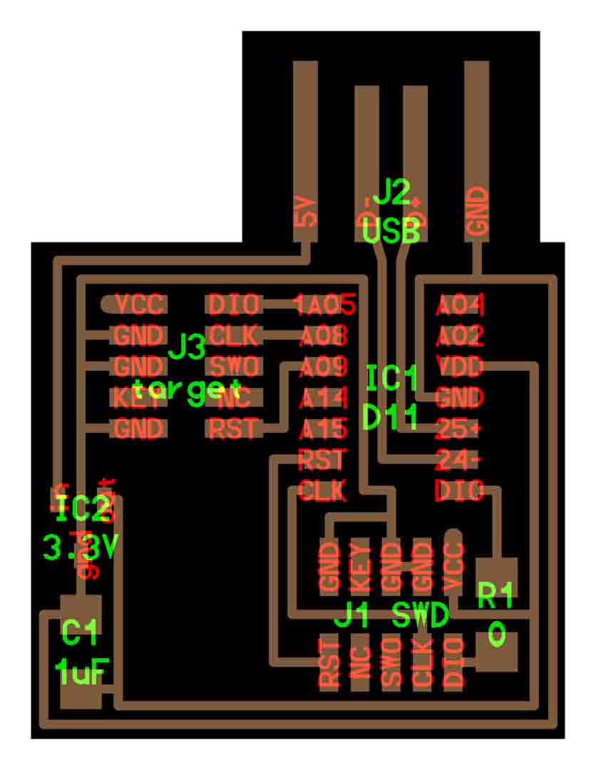 – CMSIS: Schema –
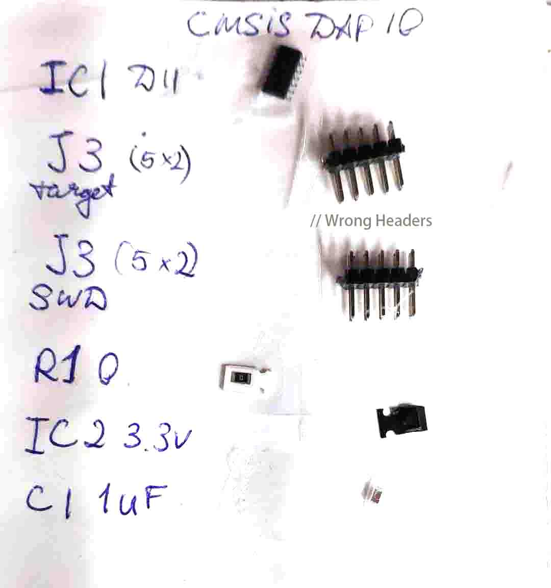 – CMSIS: Shopping List –
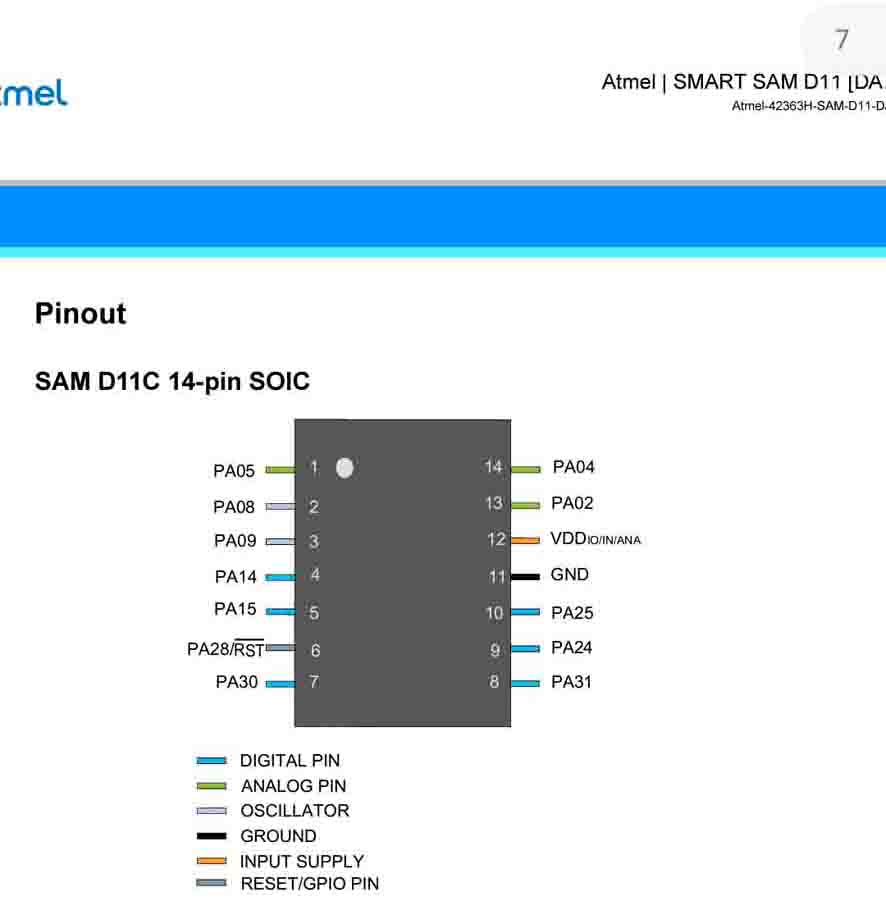 – CMSIS Controller Pinout from datasheet –
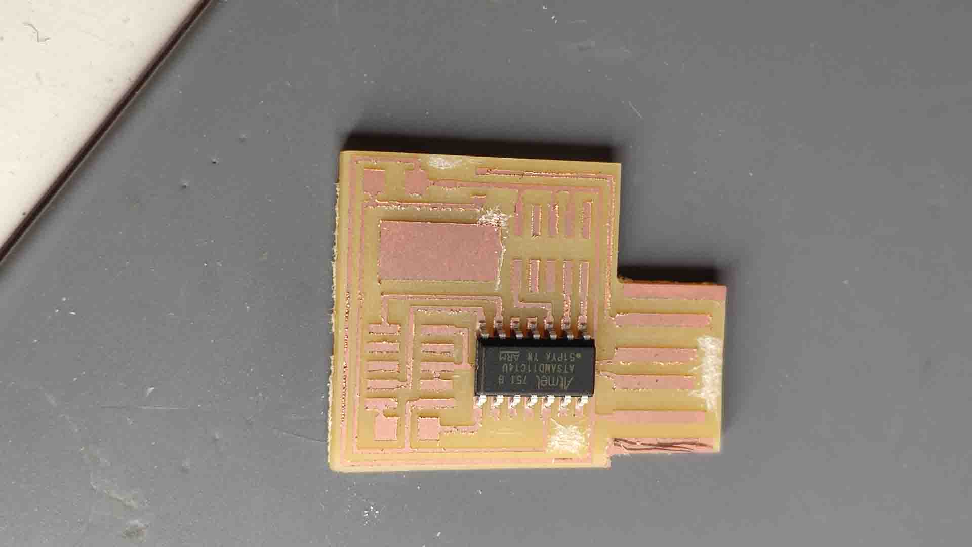 – CMSIS: Controller Placement –
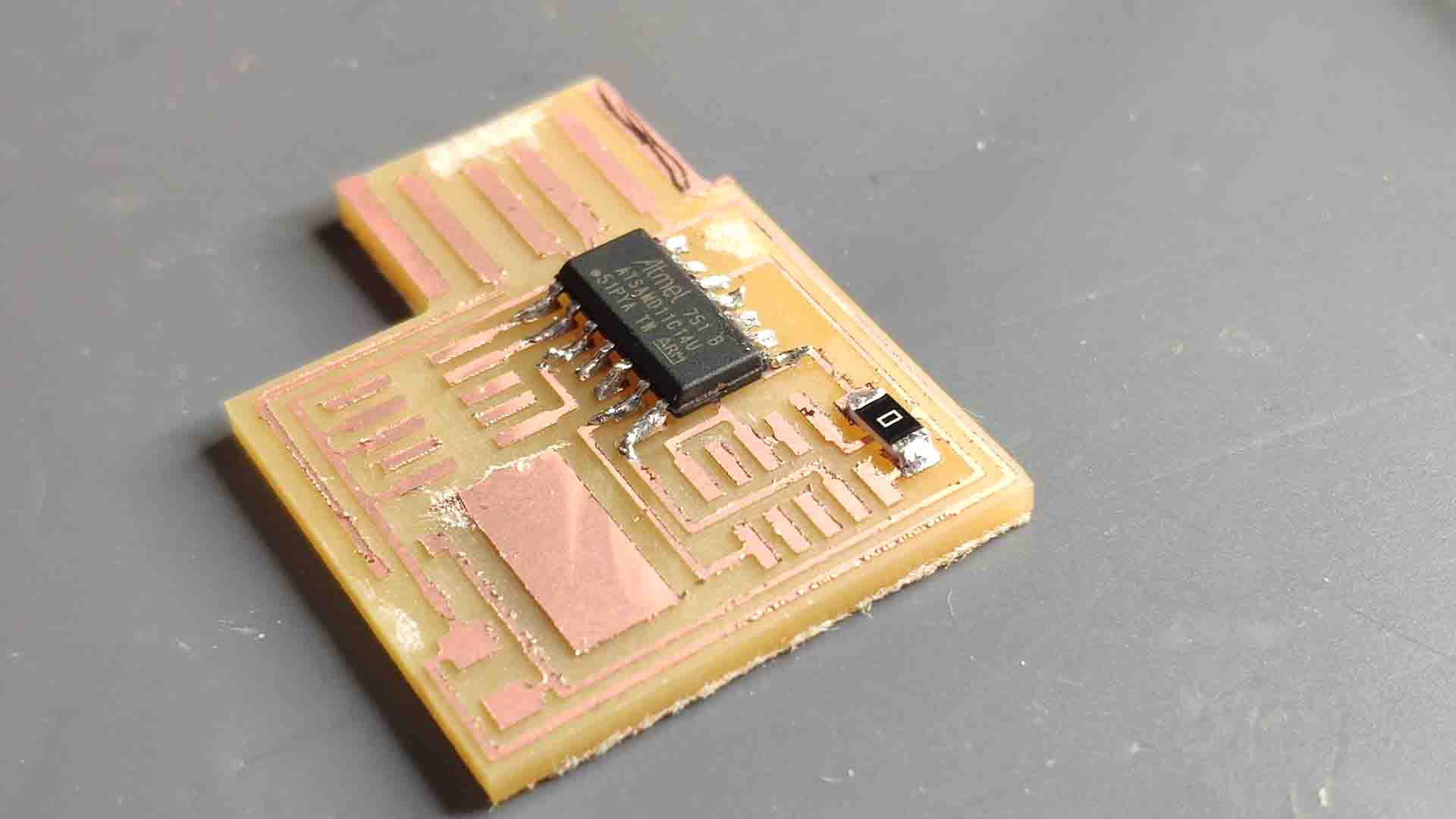
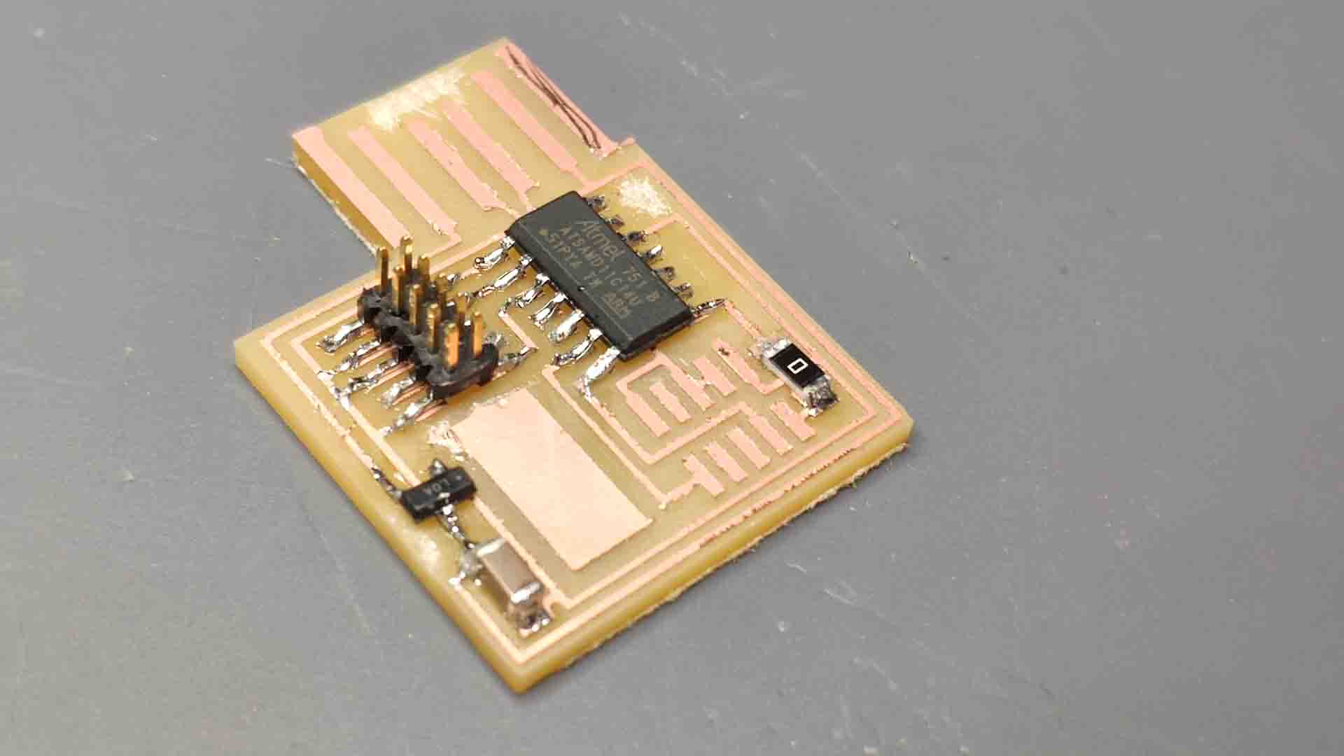 – CMSIS: Soldering –
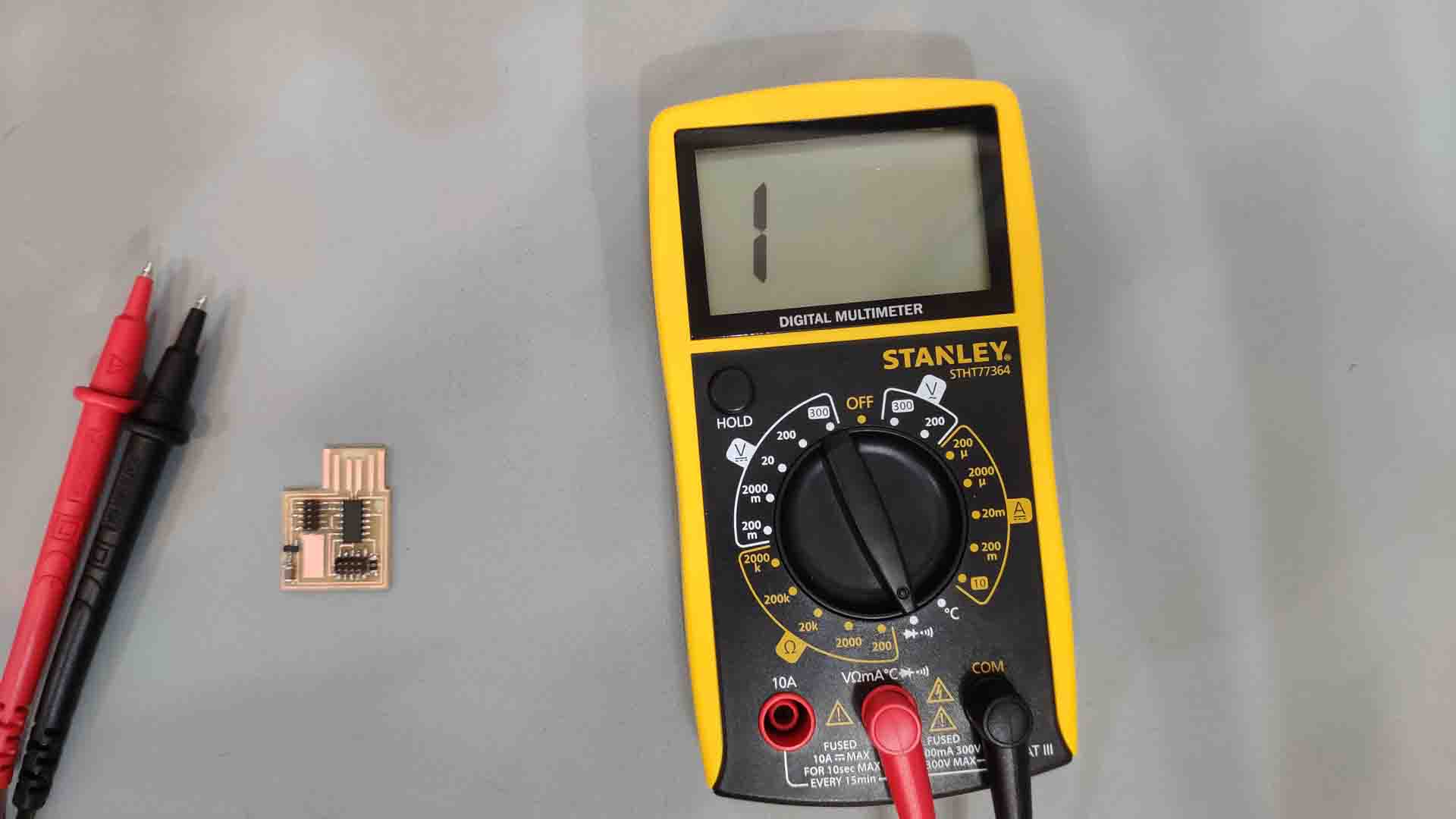 – CMSIS: Multimeter Testing –
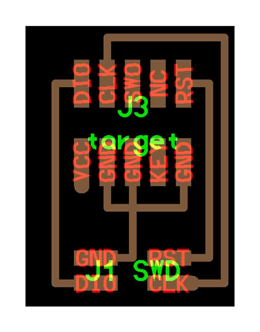 – SWD: Schema –
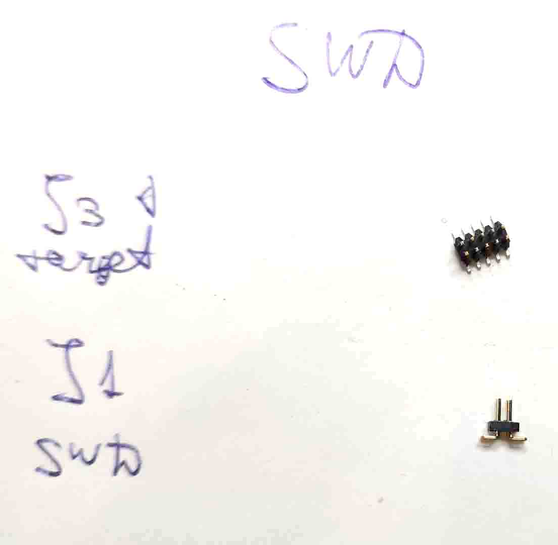 – SWD: Shopping List –
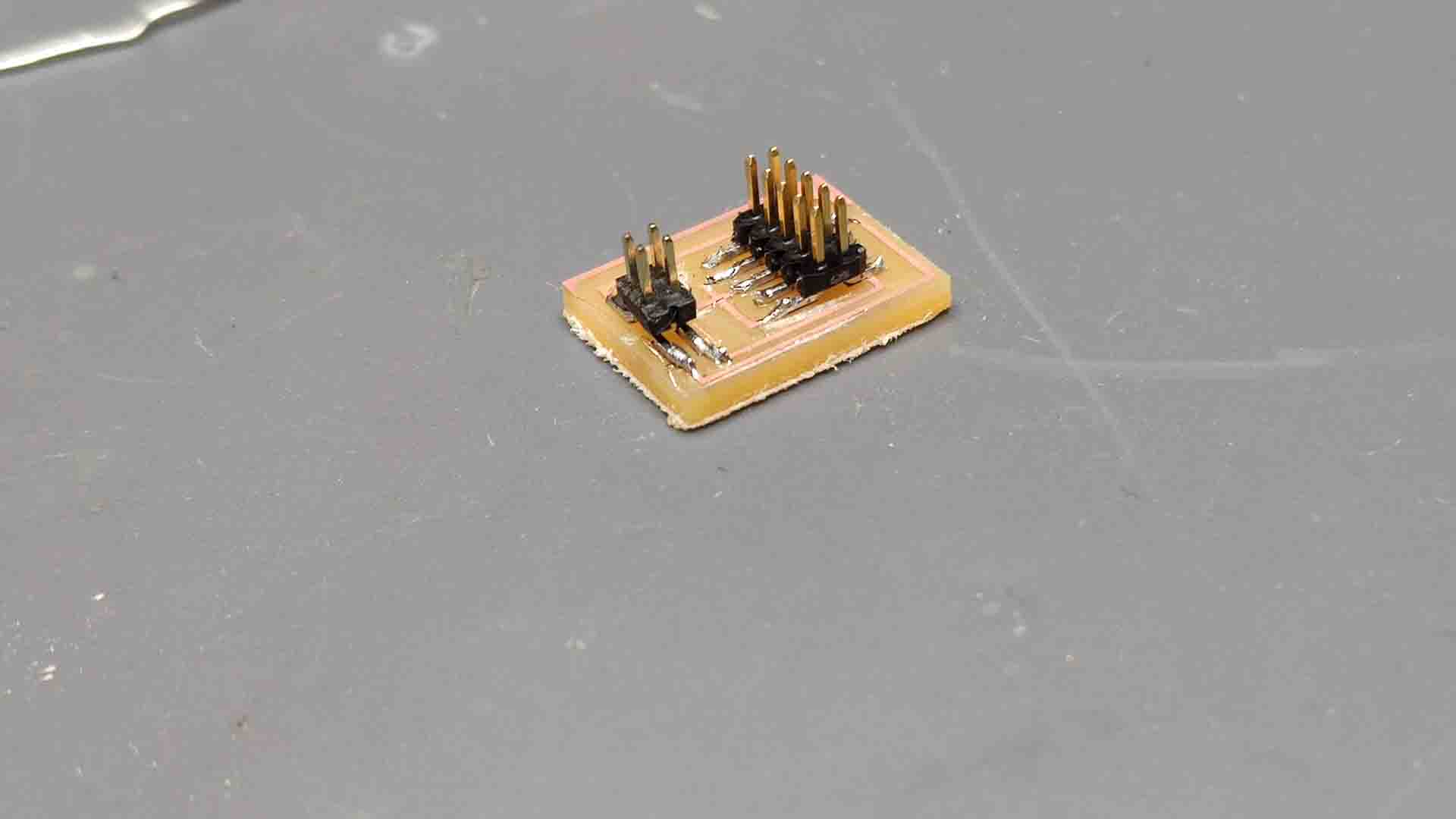 – SWD: Soldering result –
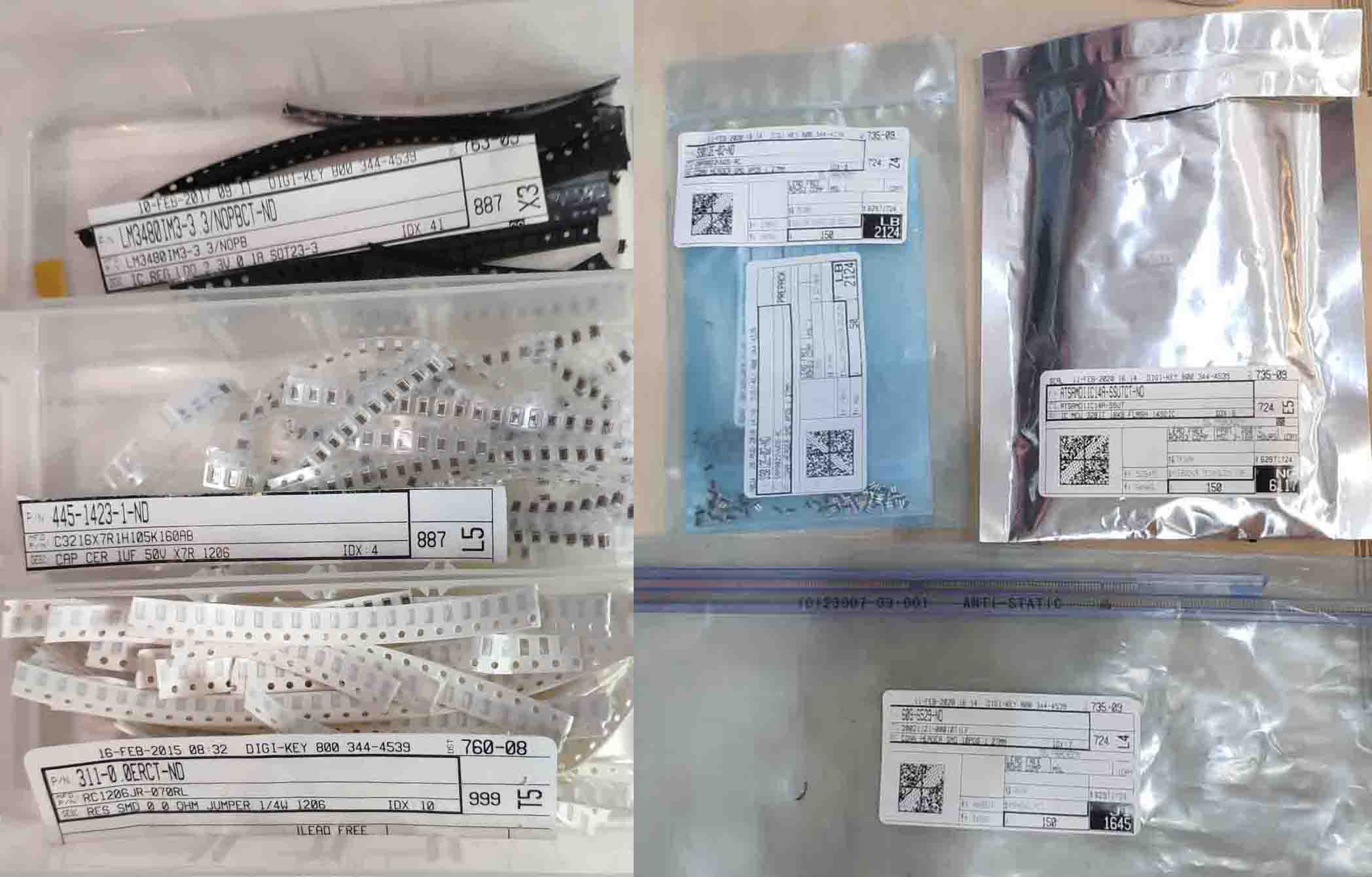 – Components Used –
Conclusions
 – Week Results –
Post Scriptum
.jpg) – Soldering Other Boards –
– Soldering Other Boards –
.jpg) – Soldering Other Boards –
– Soldering Other Boards –