Testing laser and vynil cutting and experimenting with joinery.
 – Laser –
theory
// TODO: transfer some data from conspects
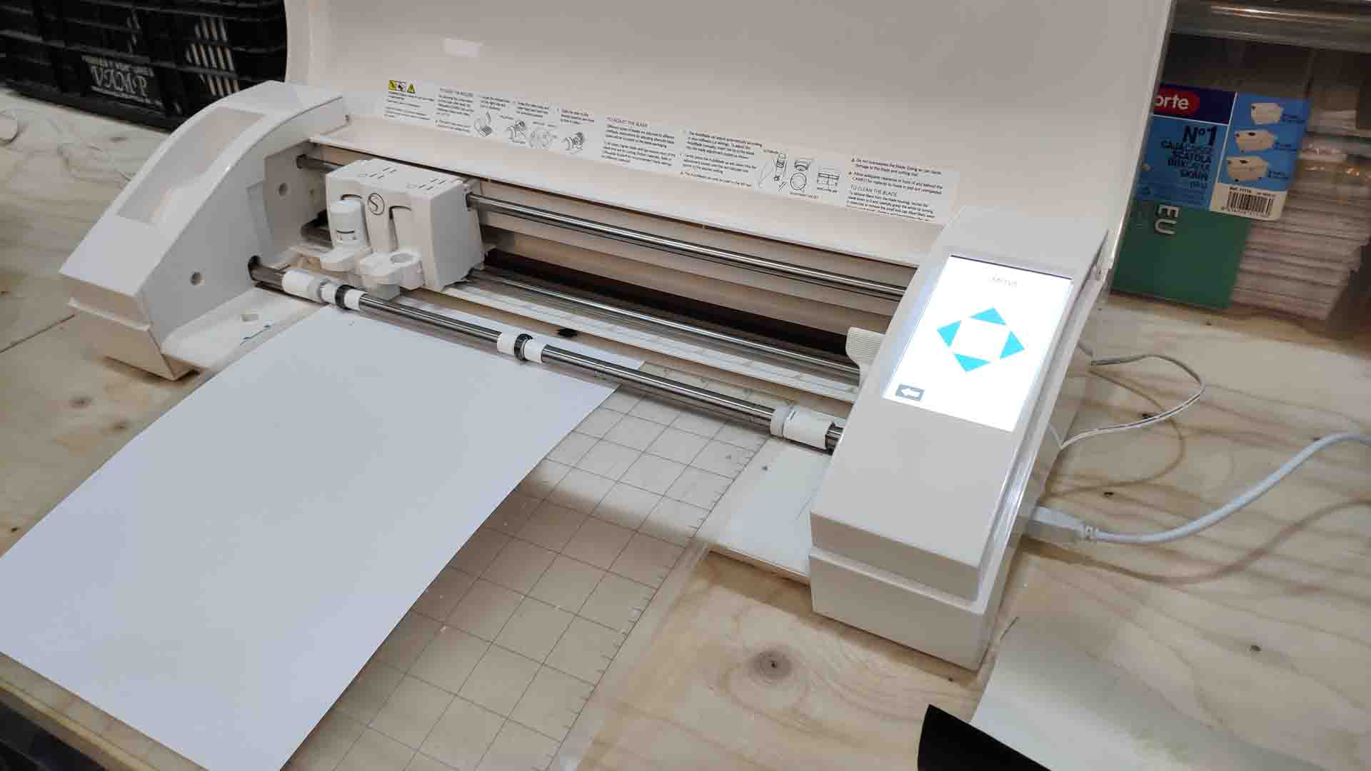 – IAAC Vynil Cutter –
 – IAAC Vynil Cutter –
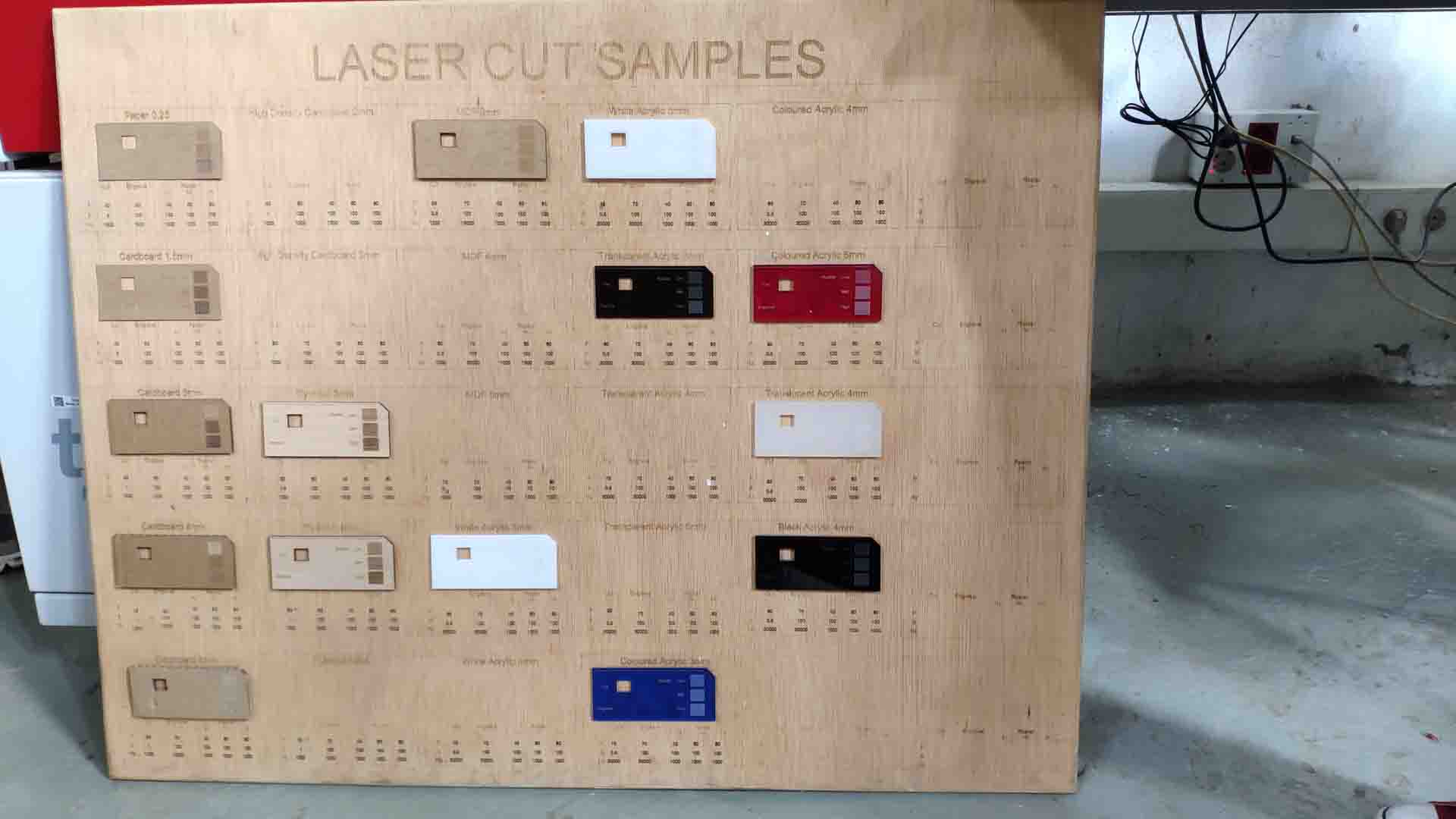 – IAAC Laser Sample board –
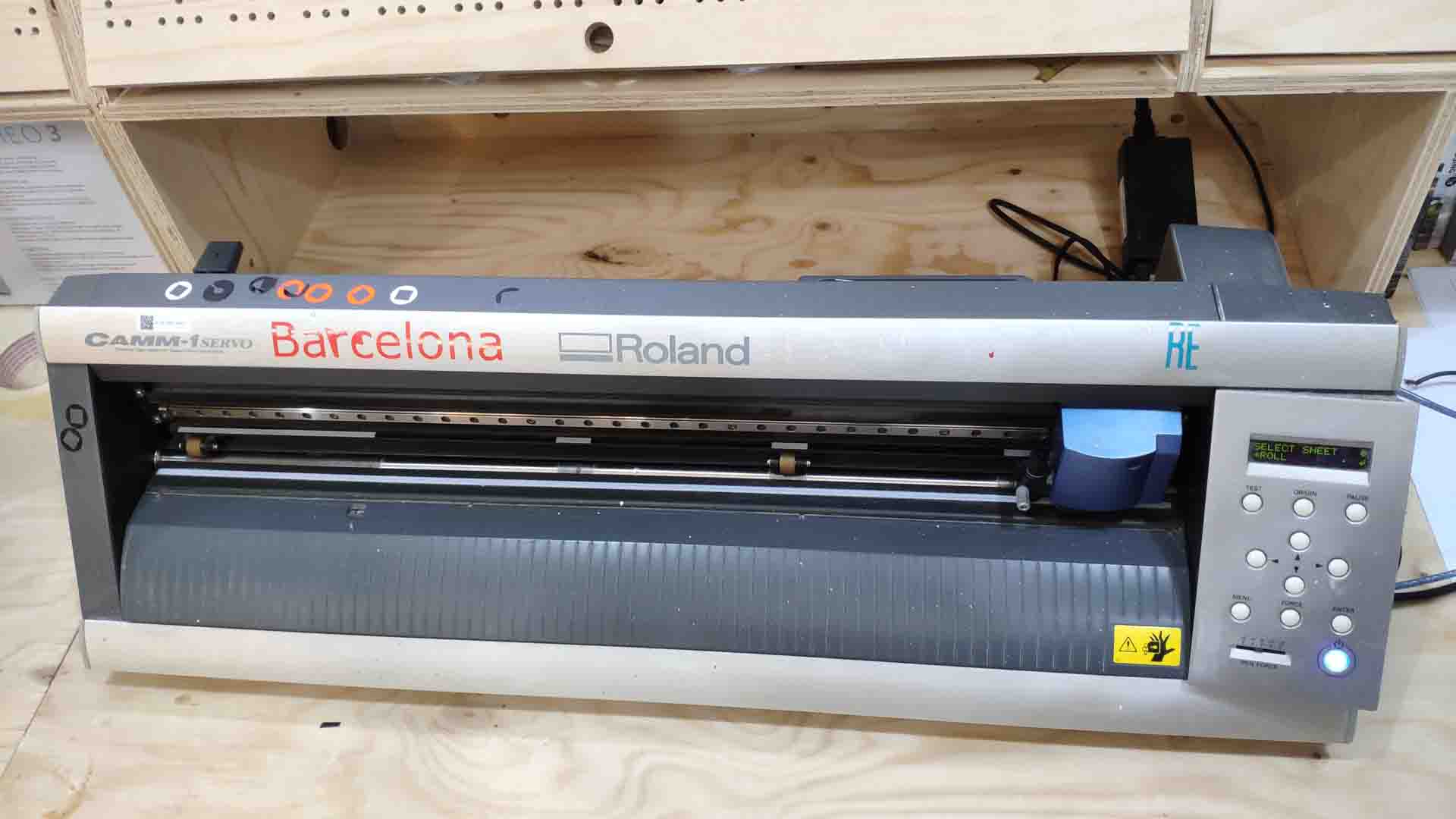
 – IAAC Laser Cutter –
// TODO: images from Tinkerers
personal conclusions
What came most surprising out of this week’s theme for me personally was consideration of the laser width for cutting. I had some experience with the laser cutting but I never relied on the joinery for connectivity but instead was interested in the precise and flexible geometry of laser-cut pieces, which comes as a pleasant relief after years of admittedly clumsily handmade models for architecture. Sure with CNC machines you understand things like drill radius and nesting, but on a smaller scale these problems used to appear to me as negligible. Yet they exist nonetheless.
This week of FabAcademy instead was a journey into a curious and smart nature of joinery. If thought out diligently and tested accurately for specific machine and specific material, these free, yet precise elements can hold themselves without need for binding agents or mechanisms. This next level attention to detail seems as a new frontier of fabrication-aware design with yet more levels of information embedded.
practice makes perfect
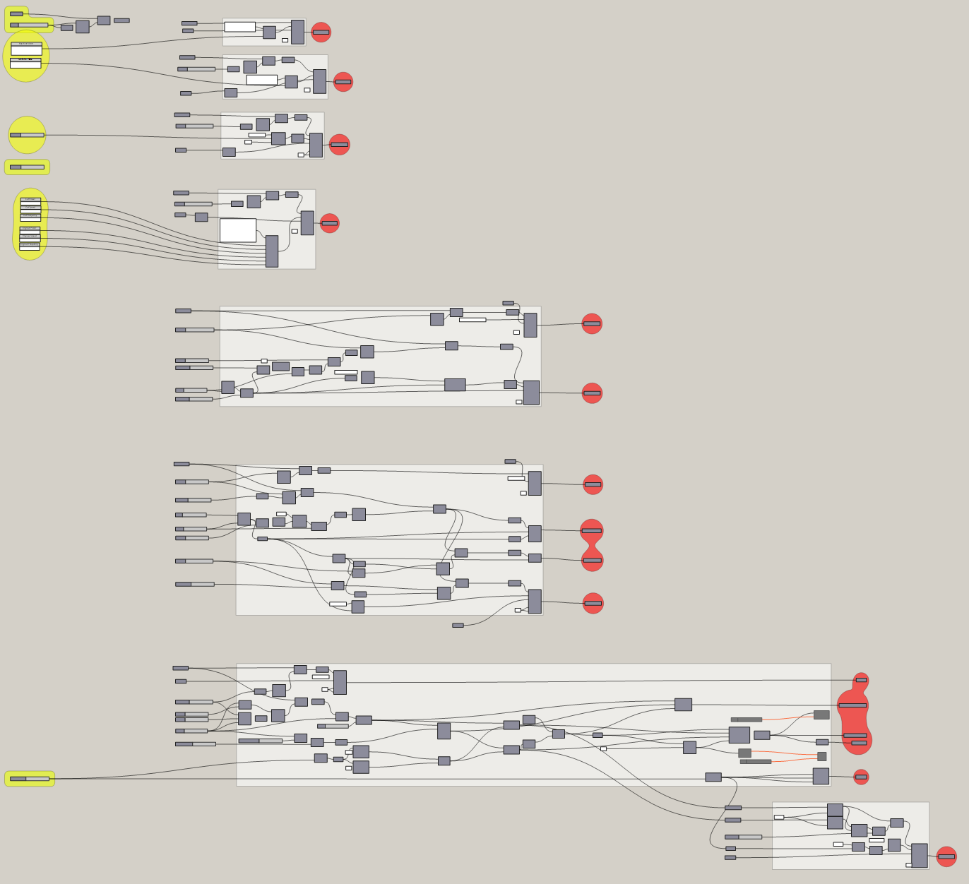
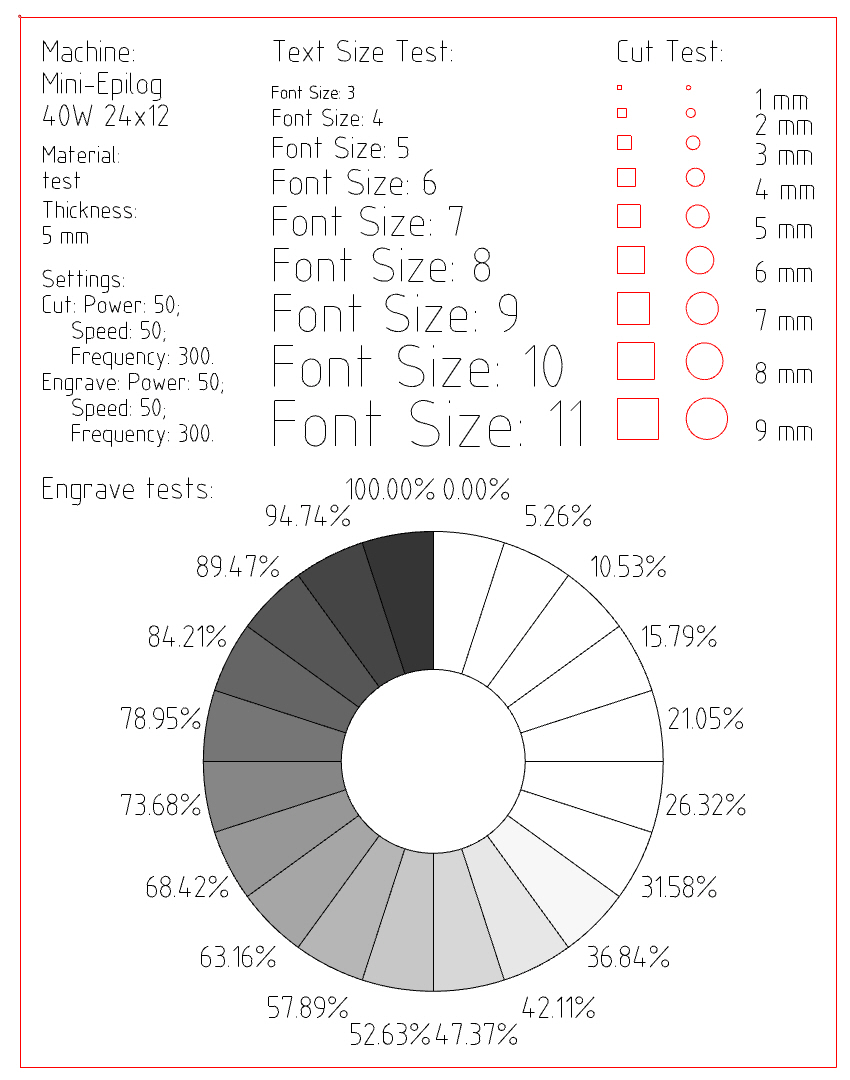
As a dramatic start, and absolute overkill yet valuable exercise, for this weeks experimentation I wanted to start assembling a set of parametric tools that could potentially serve for preparing any assembly files. This required recreating parametrically example test files, so that I could control ranges of sizes for testing, relative positioning, tolerances, machine settings.
Resulting script is capable of parametrically creating and modifying any of the settings of the test layout.
 – Laser Setting Test –
 – Laser Setting Test –
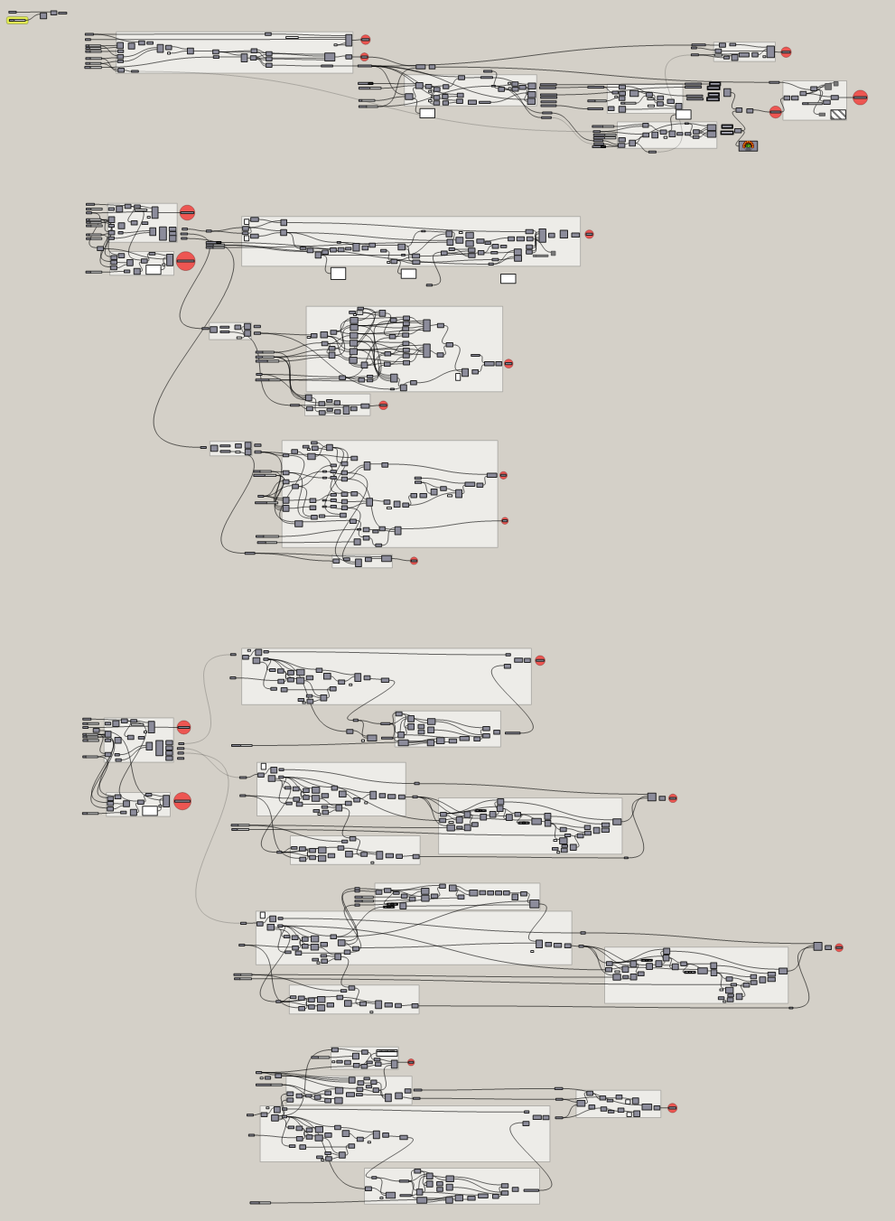
Next step was to apply this knowledge and use it for testing various established tools in working with the material. While I theoretically understand why cay one joint should perform better, I don’t have experience appplying any of them. Which makes me want to, again, parametricise the principles of joint creation. The goal in long term would be to generalize these experiments to be highly customizable arsenal I could apply to a design, both utilizing the strengths of tested systems and having flexibility to adjust it for specific case.
On the machine initial settings I borrowed from here and adapted with some small tests. Biggest issue to debug was making raster - first tests resulted in fully filled outline.
After the lab started to open up and the university campus started to open up, I finally had opportunity to pick up where I left off for the quarantine.
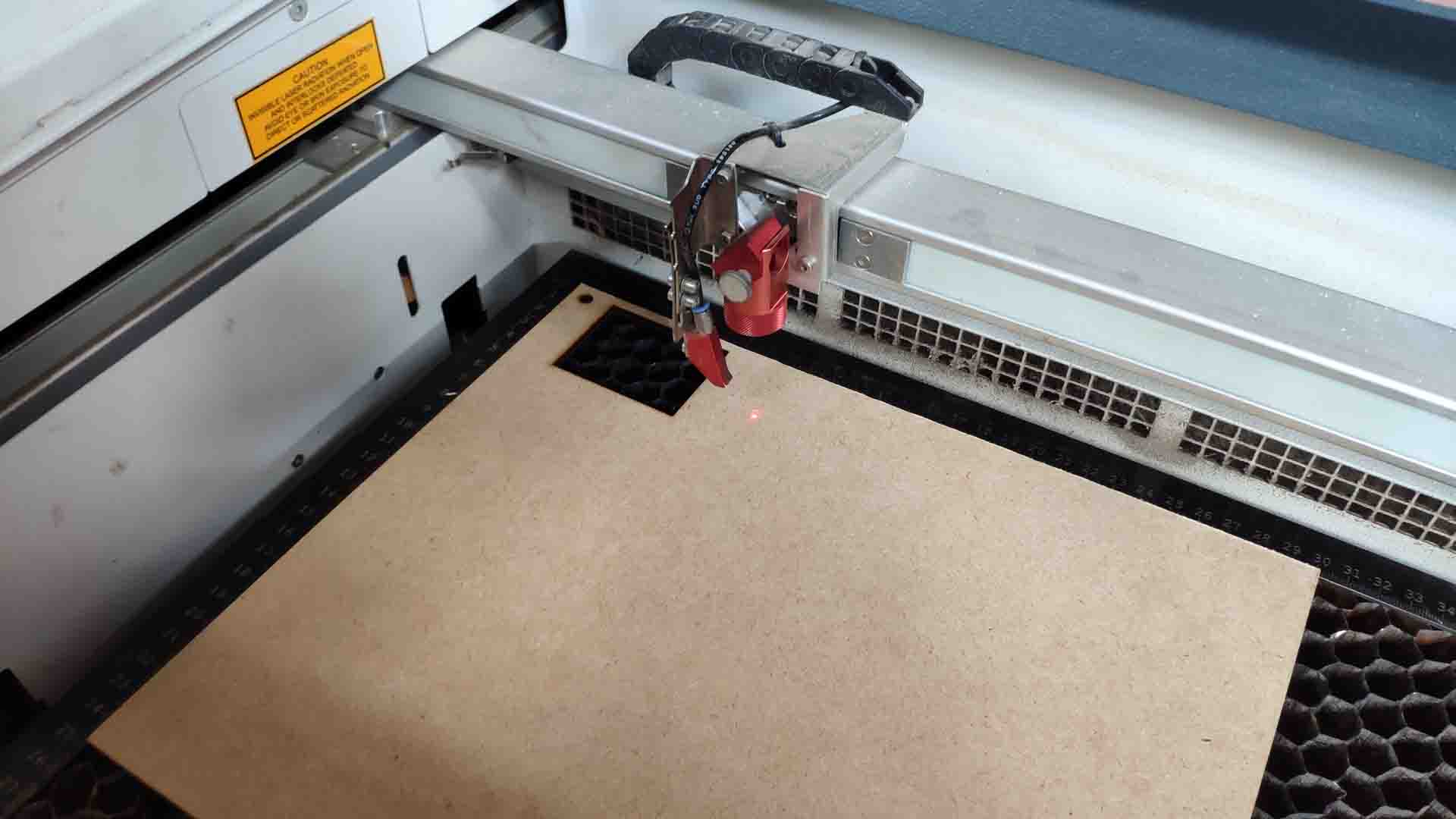
First test was thus to cut and compare various joints and surface modifications that laser-cutting can offer. Set up of the laser for my laptop was surprisingly easy and similar to installing a printer (I guess by design).
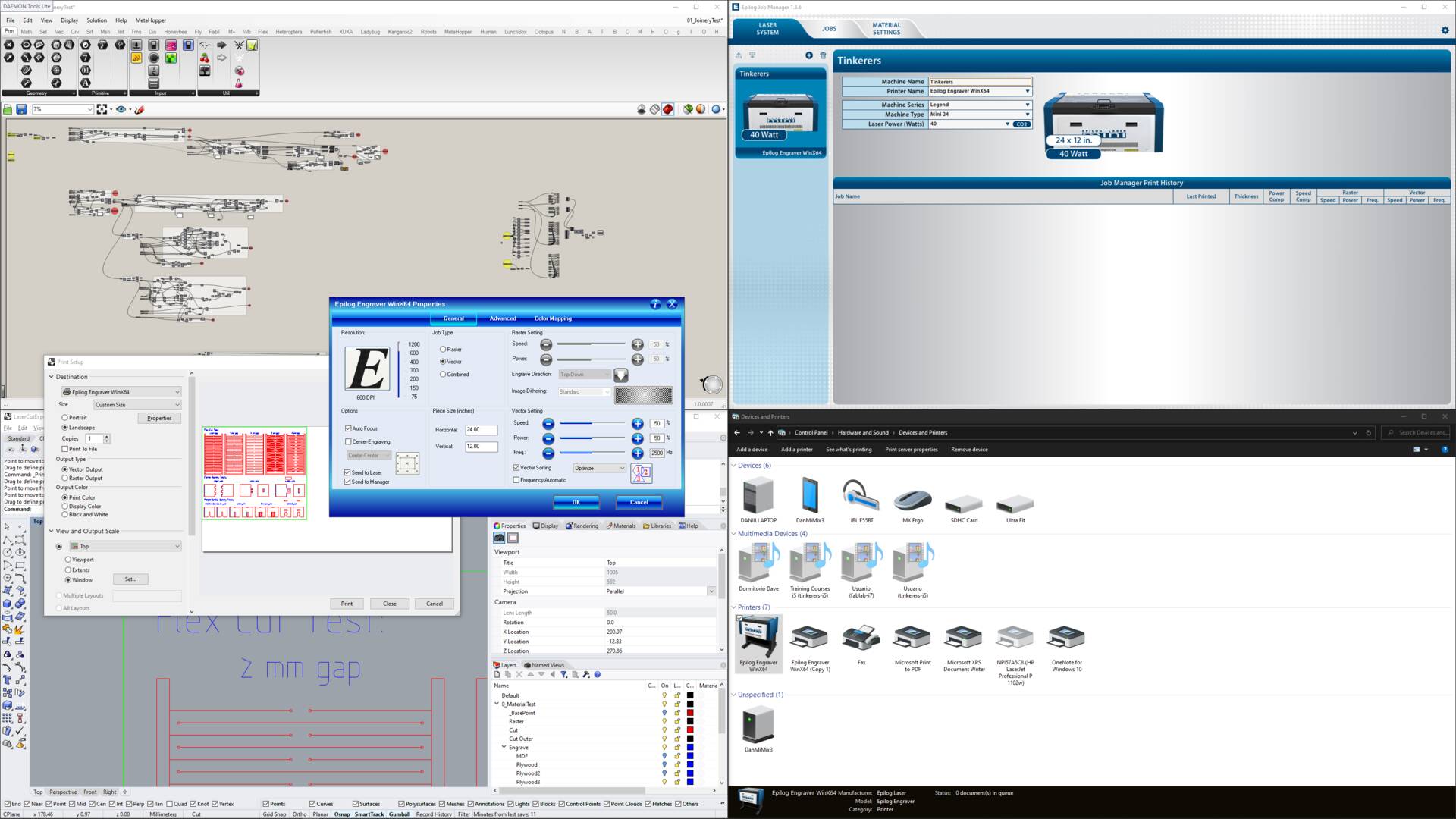
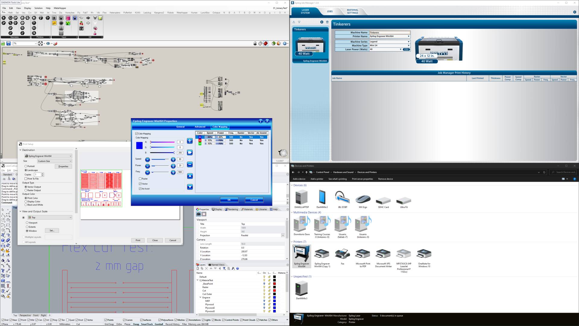 – Laser Cut Setup –
Next step was to just send to cut from Rhino 3D giving the settings I tried before with the piece as described above.
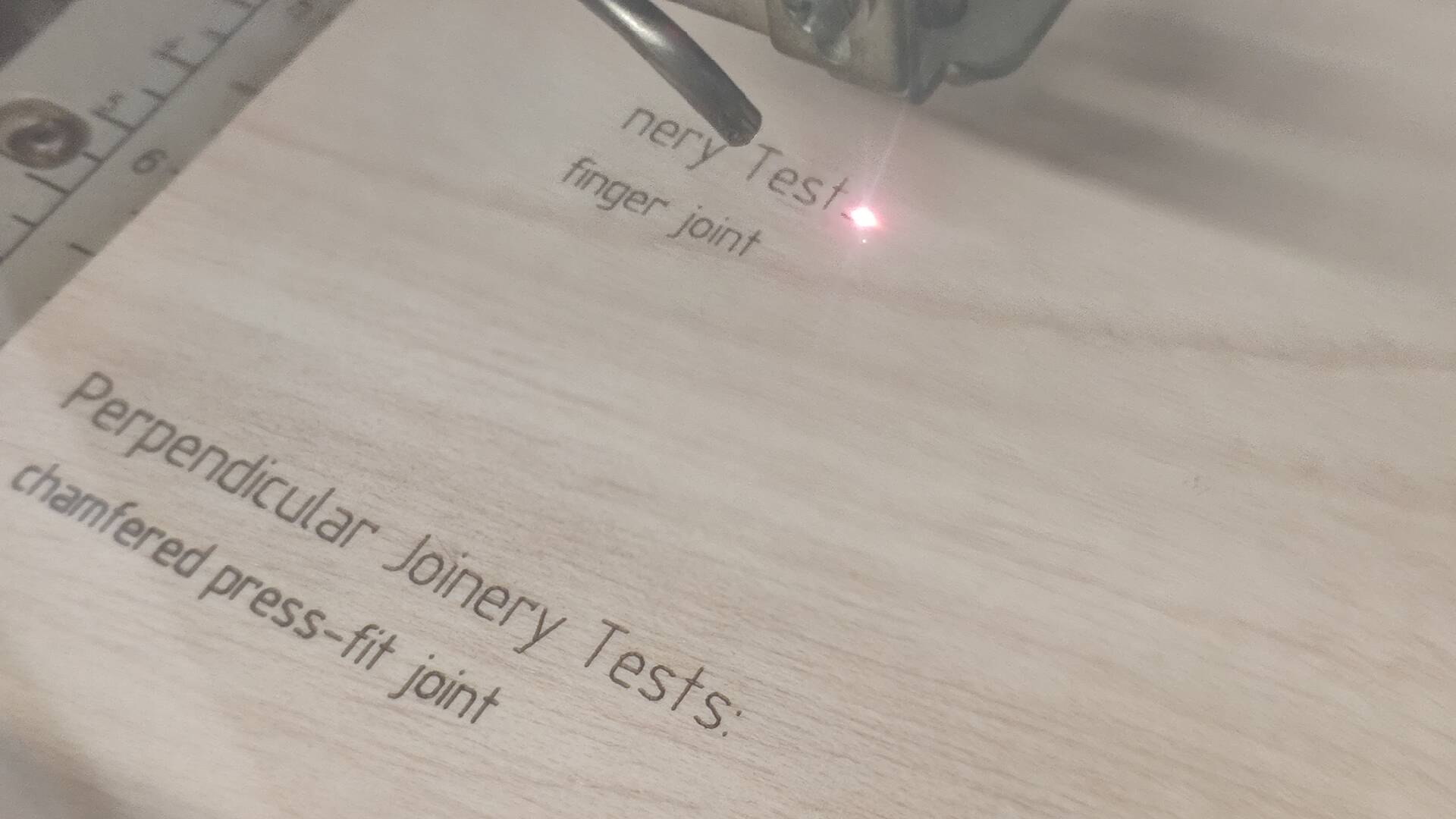
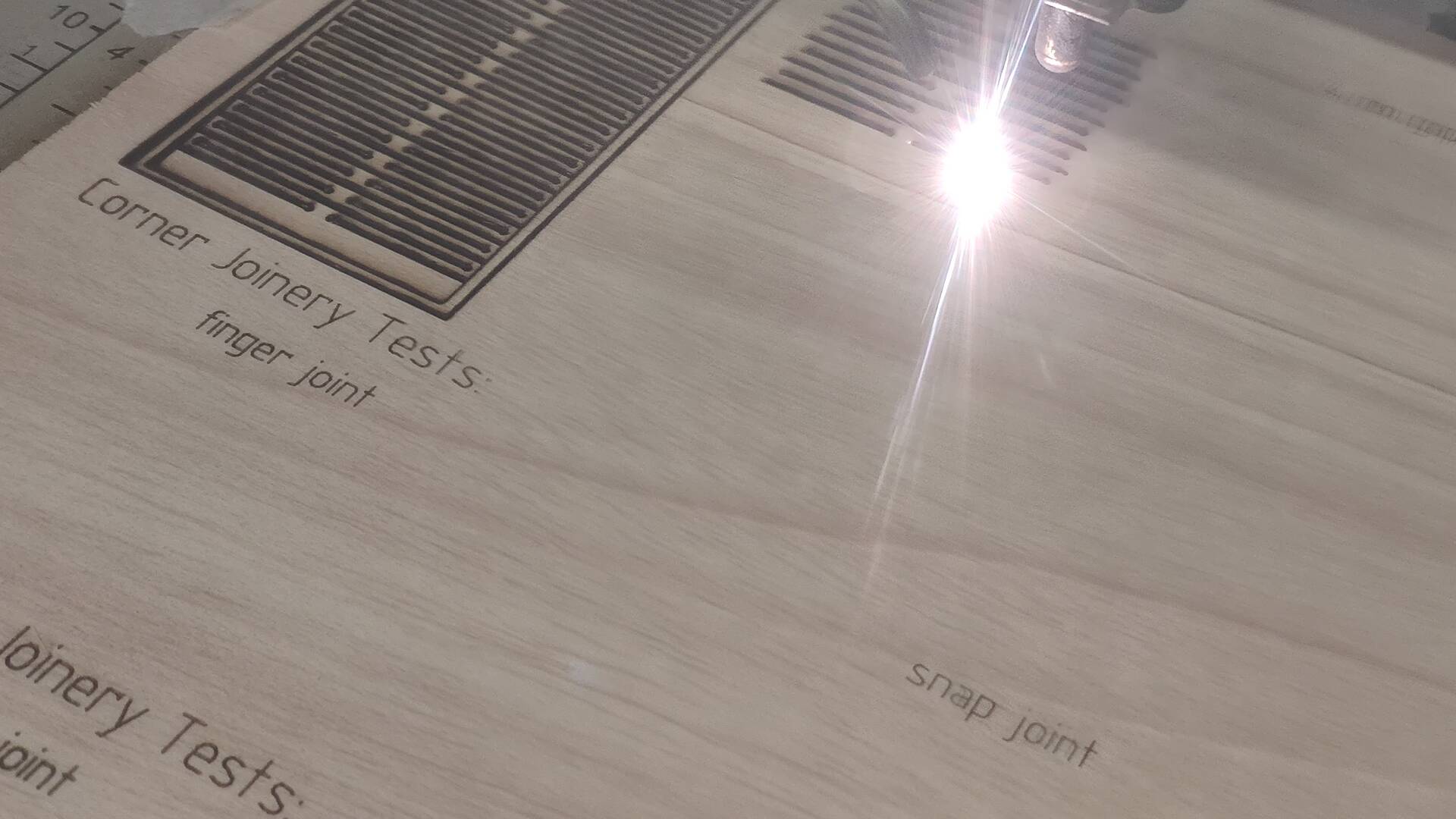
 – Laser Cutting in Tinkerers –
The only problem I found is that due to humidity over lockdown a piece I had in store for experiments got slightly distorted and in one corner focus of laser was thus under the surface and it ended up not cutting this part all the way.

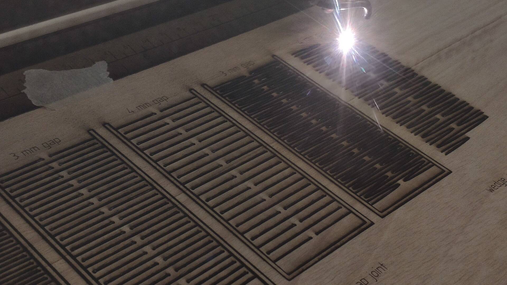
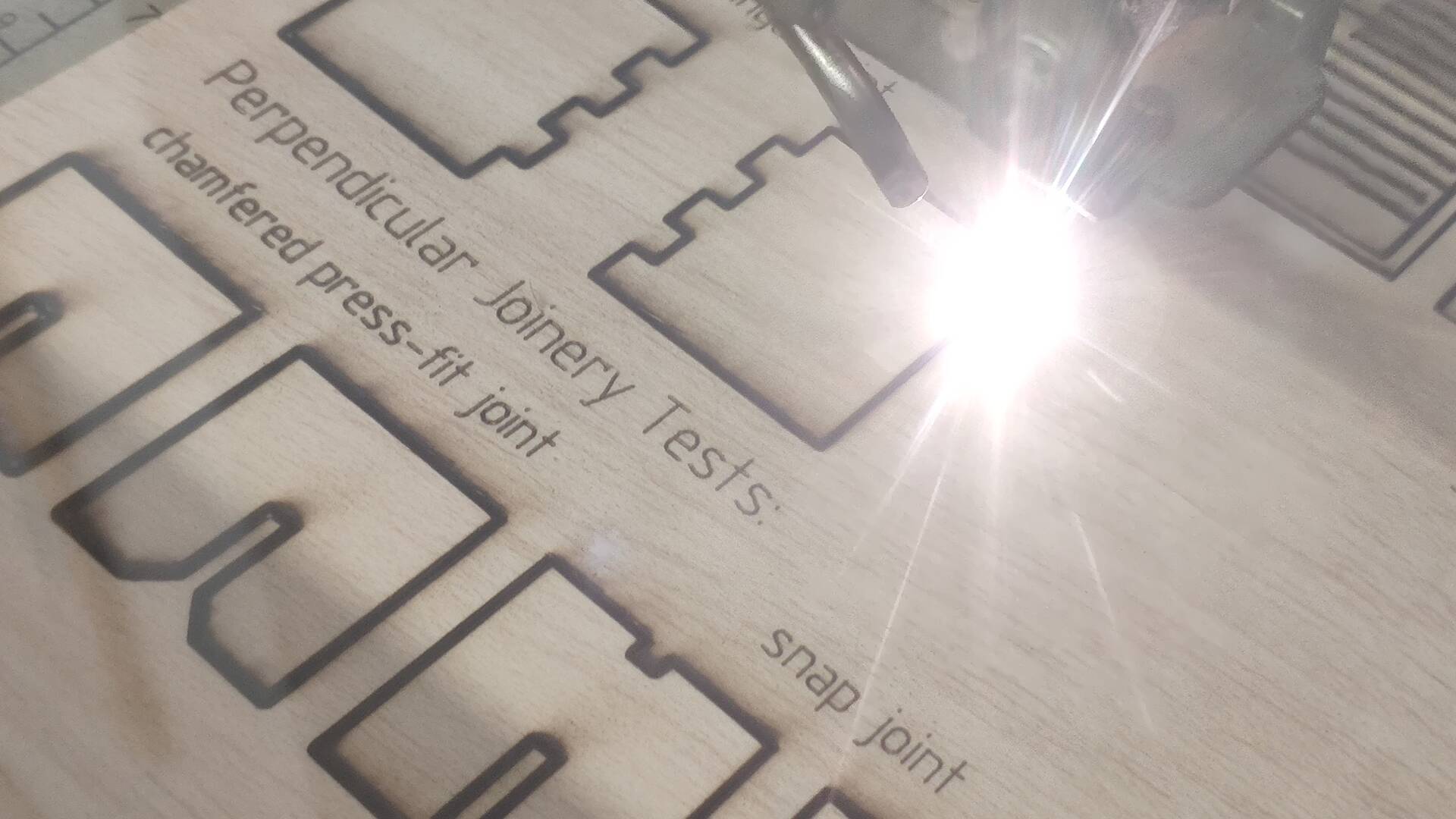
 – Laser Cutting Experiments –
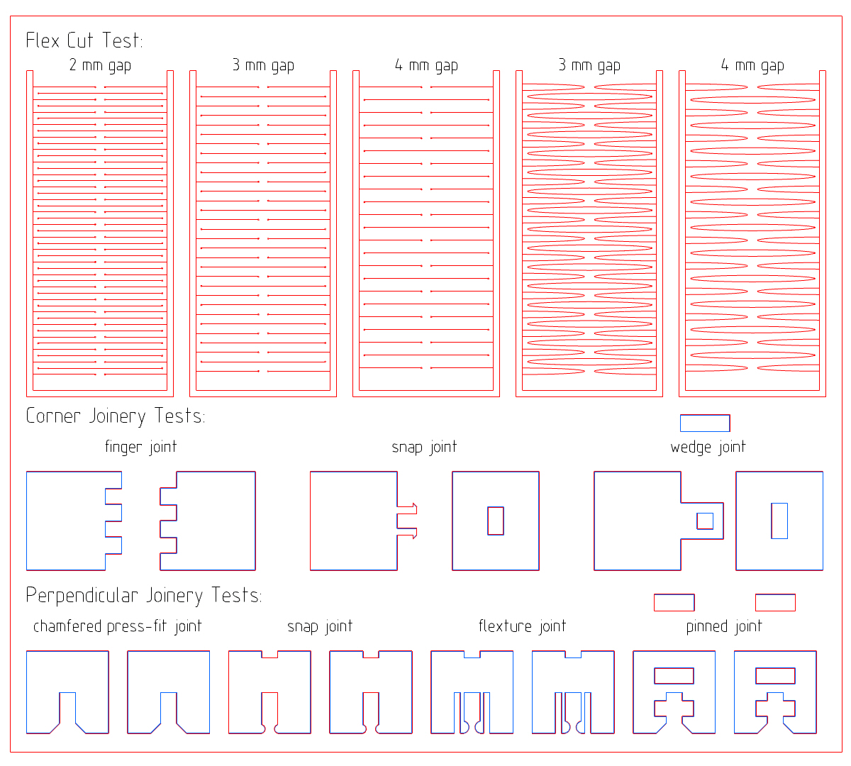
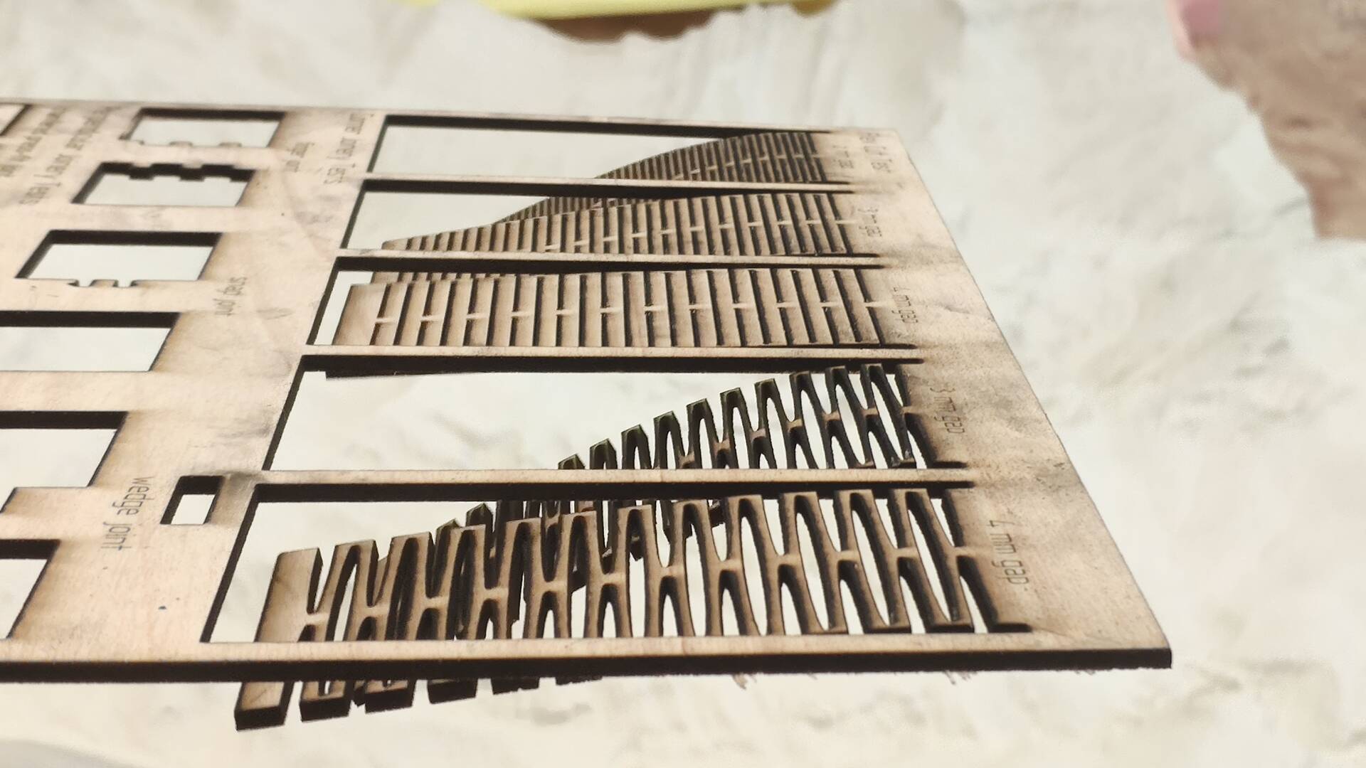
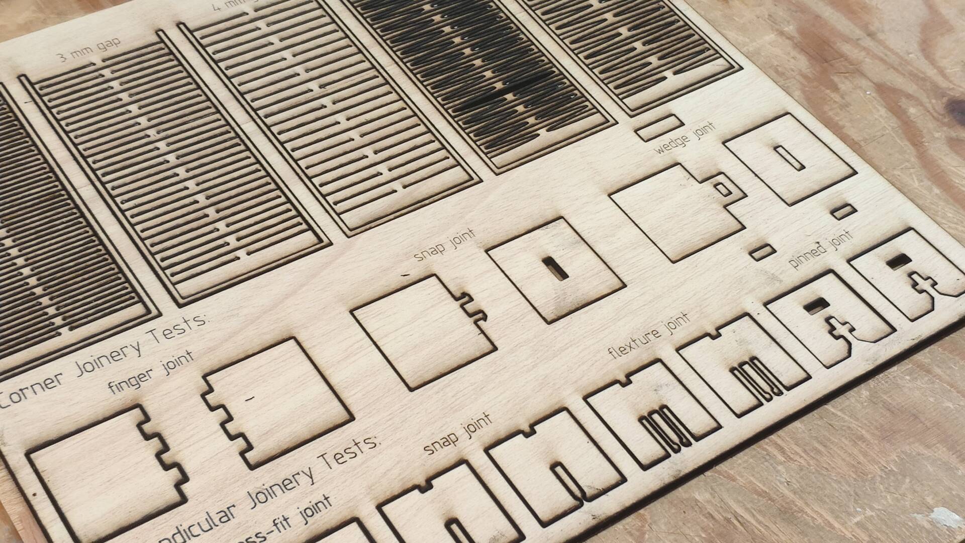
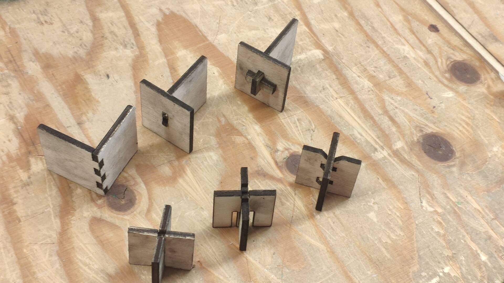
Among conclusions I found that:
- among flex cuts reasonable flexibility without losing too much of strength of surface was the straight one with 3mm gaps. Less than that was also causing excessive surface burning, which, however, I imagine can be reduced through settings tweaking for cutting.
- surprisingly even simple finger joint was standing up very strong to the force once inserted - the power of the well selected tolerance;
- wedge joint and snap joints were hardest to fit in, though, I suppose, would also be the best for one-time assemblies;
- pinned joint looked most elegant once assembled, but the tolerance for insertion piece needs to be adjusted to be tighter;
- the simplest to insert and most sturdy at the same time turned out to be flexture joint, though the durability of movable pieces is to be seen over usage. I chose this one to be used in the kit.
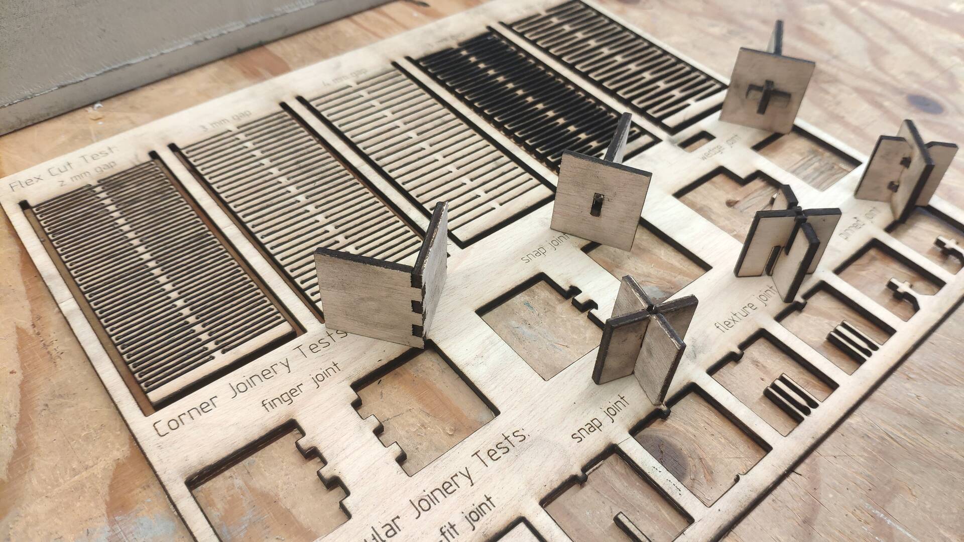
Some extra details before we move on though:
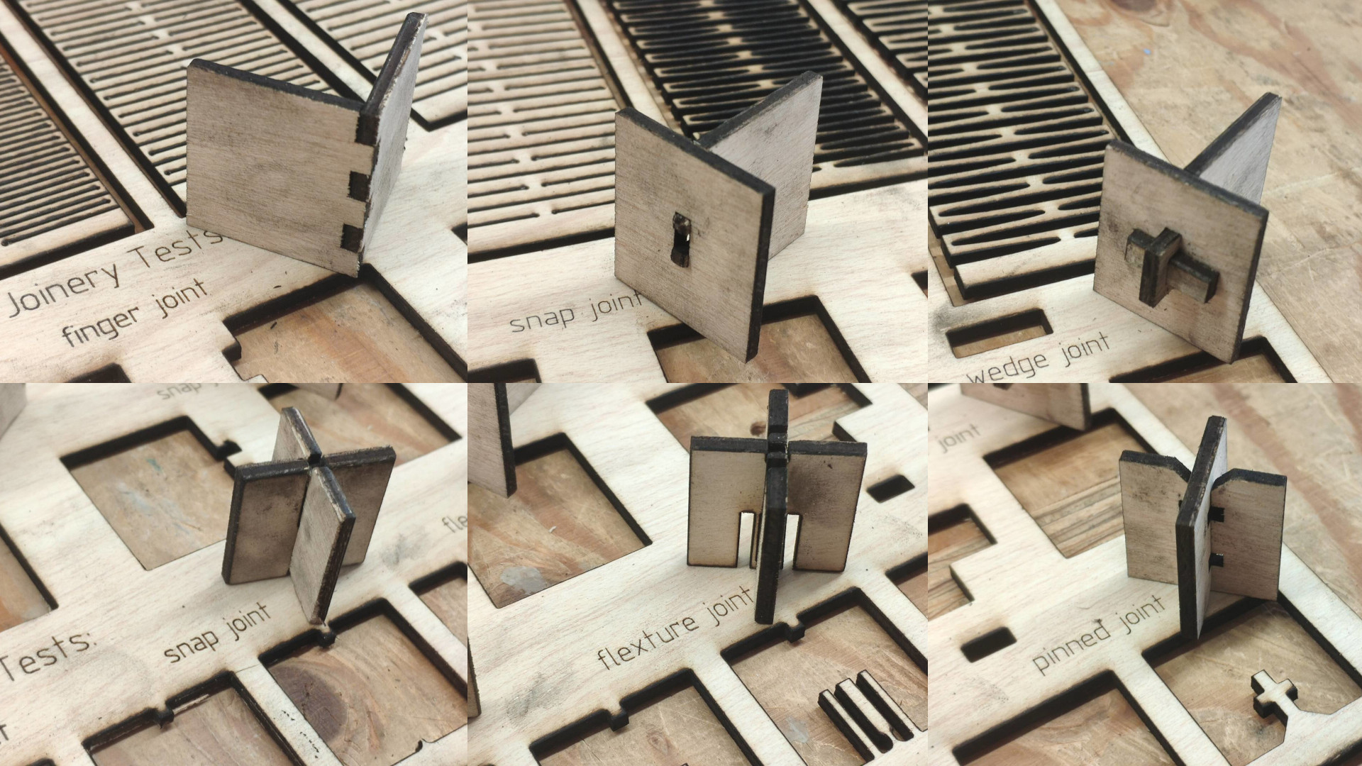 – Laser Cutting Fixture Details –
application
As an assignment I thought to try to combine most of what I’ve seen here.
The hypothesis for the kit became to focus on fascinating world of non-Euclidian geometries in a playful manner: triangles of less than or more than 180 degrees, meeting parallel lines, etc.
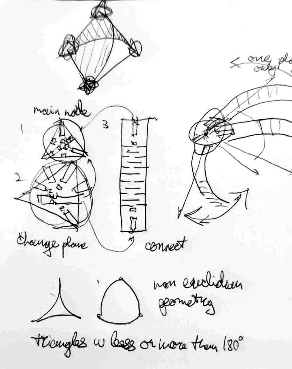 – Press Fit Kit Draft –
The kit than breaks down into three main components: main node - super-symmetric allowing multiple connection directions, flexible edge - allowing for non linear patterns (possibly of variable length), and finally plane switching element - allowing to take the system into 3D and thus providing required variable assembly as well as further expanding on concepts of non-Euclidian mathematics into space.
// TODO continue
Work File: