Chaotic order
Brief overview of the last week prototype of the project.
Design
– TODO: add schematic of device –
Having a clear idea of the functionality and potential size I drafted a parametric model in Grasshopper. The design consists of:
- brain of the device (a board with esp32, screen as output and touch pads as inputs);
- front and back flat panels - transparent to reveal the inner world of the device;
- top and bottom caps holding device together;
- side panels clipping into caps securing the device without any joints or glue.
– TODO: add design screenshots and renders –
With this done, I extracted all the pieces and started to test every element.
3D Print 1
As a rough prototype I printed first pieces with a conventional [TODO: name] 3d printer. First print went awry, but I got it to behave.
 – 3D print 1: fail –
– TODO: 3D print 1: fixed –
Laser Cut
Next I needed to make sure the outer panels would be able to host screen of the device with tight tolerances. Quick trip to the laser cutter [TODO: name] did the simple job.
.jpg)
.jpg) – Panels Laser Cut Process –
– Panels Laser Cut Process –
Assembly 1
Combining the two I got this:
.jpg)
.jpg) – Assembly of principal pieces –
– Assembly of principal pieces –
Vynil Cut
Then I made a matrix of conductive pads cut with vynil cutter [TODO: name], connected to touch pins of ESP32.
– TODO: find first try –
Once I made the code work and made sure this would work I vynil cut it again in the dimensions needed and transferred to the panel, separating them with a layer of transparent tape.
.jpg) – Touch matrix cut –
– Touch matrix cut –
.jpg)
.jpg) – Touch matrix transferred –
– Touch matrix transferred –
Assembly 2
I added this part to the prototype to confirm everything works together:
.jpg) – Assembly 2 –
– Assembly 2 –
.jpg)
.jpg) – Assembly 2 Details –
– Assembly 2 Details –
3D Print 2
Now that the scale and tolerances were confirmed and main elements set, I wanted to reiterate on the print to use the Photon [TODO: machine model and print type].
.jpg) – The machine –
– The machine –
.jpg) – Printing Process –
– Printing Process –
.jpg) – Resin curing device –
– Resin curing device –
.jpg) – Oven –
– Oven –
.jpg) – Processing the result –
– Processing the result –
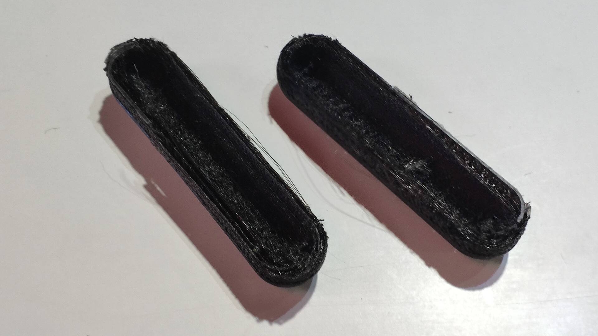
Then directly using this printer I thought to print sides.
.jpg)
.jpg) – Sides’ models prepared to print –
– Sides’ models prepared to print –
.jpg)
.jpg) – Printing Process –
– Printing Process –
In experimenting with machine I encountered this weird bug - slicing was successful on computer, but upon reading by the printer the sections were all like the one displayed on the screen.
.jpg) – Error in slicing –
– Error in slicing –
In the end print failed. Checking the result with guys in the lab we thought the problem could be that the mesh in the liquid bed got a bit clogged and accumulated material got stuck mid-way through print messing up the design. Possibly even the same error in slicing might have caused the final print to fail since it might have deposited excess material on the mesh. Similar artefacts were present in first try but didn’t have enough mass to mess up the print.
– TODO: failed piece –
Assembly 3
This is the combination with replaced caps.
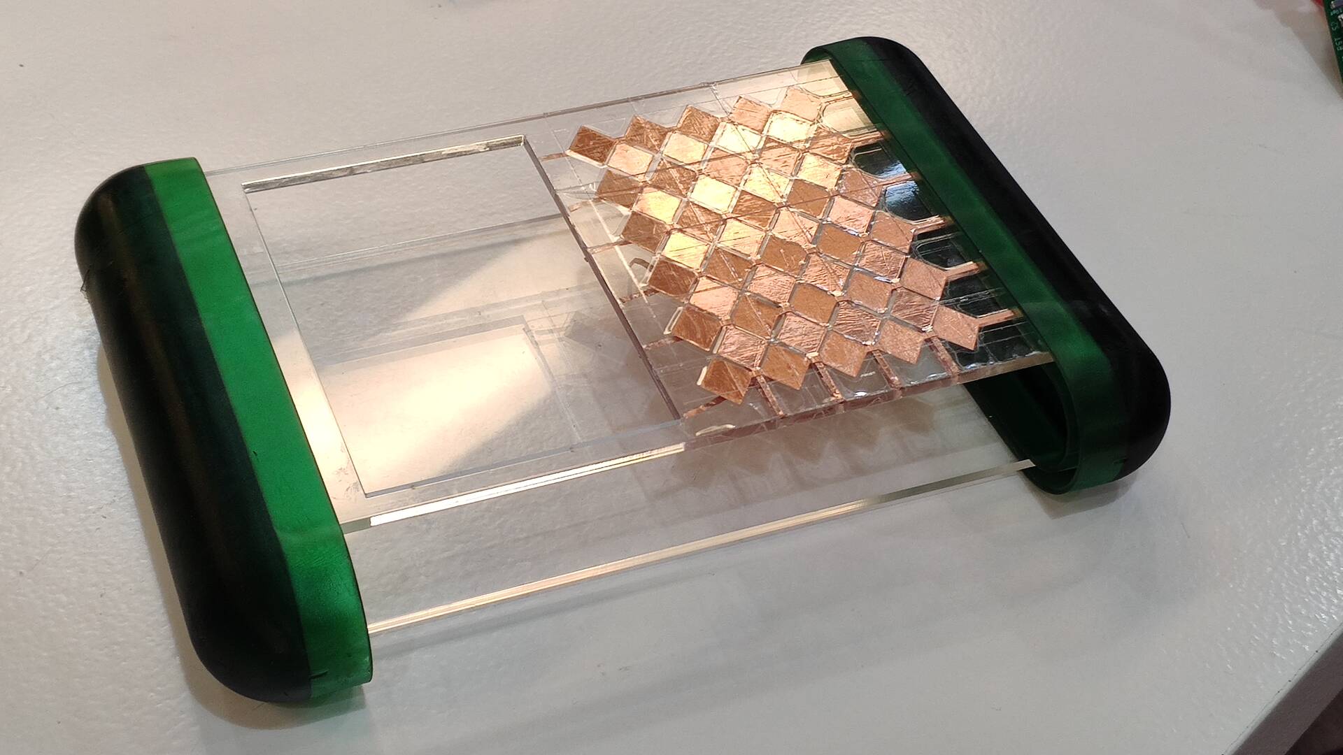 – Assembly 3 –
Electronics Prototype
Now that the physical body is established I shifted focus on the electronics.
To start off I wired everything up with the barduino [TODO: put link] I made previously in the electronics weeks, that uses the same chip I was planning to use. Biggest hustle was to get the screen to work:
.jpg)
.jpg)
.jpg) – Screen Test –
– Screen Test –
Extremely unintuitive brain-teaser was figuring out which pins I can actually use since I had to reserve the touch pins for touchpads, but had to also connect screen to the board.
After making sure the pins and code were working, I designed the board to be the brain of my device. I assembled touch pins into one connector, so that later I could vynil cut a connector belt between pads and the board, to clean up the insides and eliminate wiring completely.
– TODO: schematic of the board – – TODO: images of the board –
This is the moment where the time of the cycle has ran out, and I had to leave it for future reiteration.
** TODO: Files: **
To be continued
Plans for next prototype:
- confirm prototype functionality;
- think through energy source;
- fabricate internal holders for final elements to secure them inside;
- develop networking and protocol for communication;
- develop Unity-side communicator scripts;
- develop UI for the screen;
- having final layout redo touchpads vynil cut to go directly to the board on a transparent plastic film;
- evaluate remaining pins to add additional input methods;
- consider splitting touch and screen control into independent chips linked to esp32 independently - to allow more inputs to be linked as well. This would also allow to enable screen’s touch functions.