Ninth assignment
Date
18 Mar 2020
The aim of this week's assignment is to summarize the information that we have read about the microcontroller that we had designed and programmed in Week 7 Electronics Design .
Datasheet
When I started reading the datasheet, it seemed a little bit overwhelming because it contains a lot of information and details ! but I tried to focus on the main points of the ATtiny44 microcontroller that I have used in my board.
We are surrounded by Embedded Systems !
What are Embedded systems ?
Embedded systems is a combination of computer hardware with software embedded in it,designed to do specific functions and used to control many devices.
Some applications for embedded systems : cars, robots, drones, smart phones, medical equipment, game machines, and more.
The Embedded Systems basic components :
Microcontroller which is considered as the brain of the embedded system.
Input Devices such as sensors and buttons.
Output Devices, also known as “ Actuators “, such as motors and LCDs.
What is Microcontroller ?
Microcontroller is a functional computer system on a chip that comes in different sizes and is dedicated to one single task.
Microcontroller components :
Processor or CPU.
Two main memory : Program memory and Data memory.
Input-Output Ports (I/O).
Serial Ports.
ADC and DAC.
Timers.
Interrupt Control.
While reading the datasheet, I found an useful information about the ATtiny44 microcontroller that I used in my board.
The main characteristics of Attiny44 :
Manufactured by Atmel / Microchip.
Low-power CMOS 8-bit microcontrollers.
Number of Pins : 14
CPU : RISC 8-Bit AVR
RAM : 512 Bytes
EEPROM : 512 Bytes
Program Memory : 8K
Program Memory Type: Flash
ADC : 10-bit
ADC Channels : 12
Operating Voltage: 1.8 – 5.5V
Oscillator: up to 20MHzv
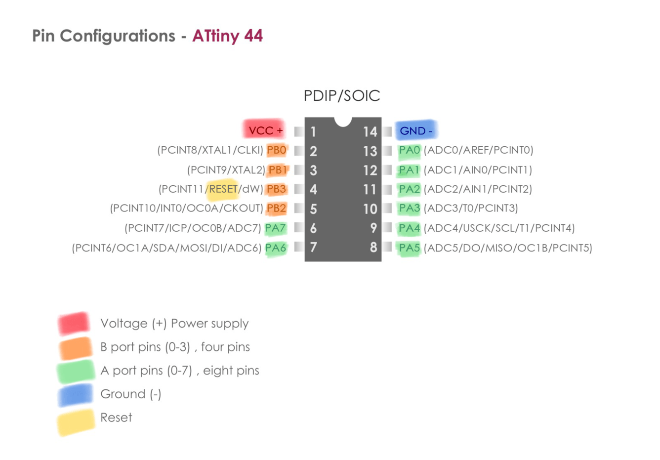
ATtiny 44 Pins:
As a visual learner, I marked all the ATtiny 44 pins with different colors to clarify their locations and functions.
programming
As you know, during the COVID-19 pandemic and the total lockdown, I couldn’t complete the soldering process of my PCB that we made in week 7 because we didn’t have the possibility to access our lab. So, As a plan B, we decided to work with Arduino Uno.
What is Arduino ?
Arduino is an open source programmable circuit board that can be integrated into a wide variety of makerspace projects both simple and complex.
The Arduino programming language is a simplified C/C++ language.
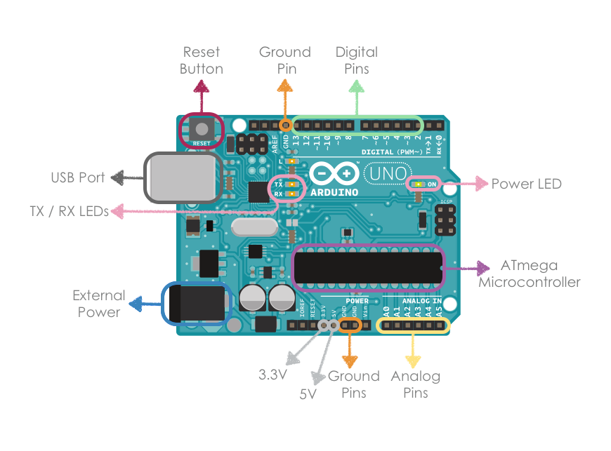
The components of Arduino UNO board :
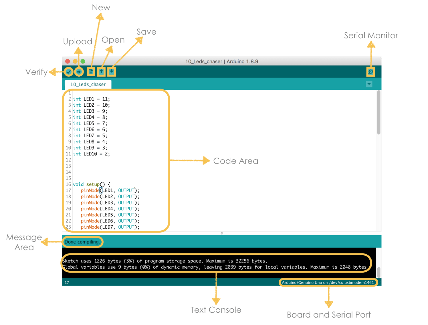
To program the Arduino board, I started by using the Arduino Integrated Development Environment (IDE) Software to write the code and upload it.
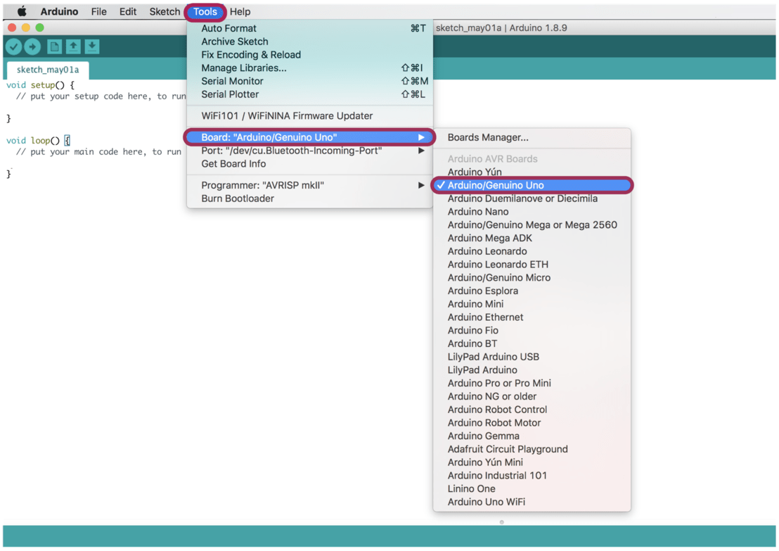
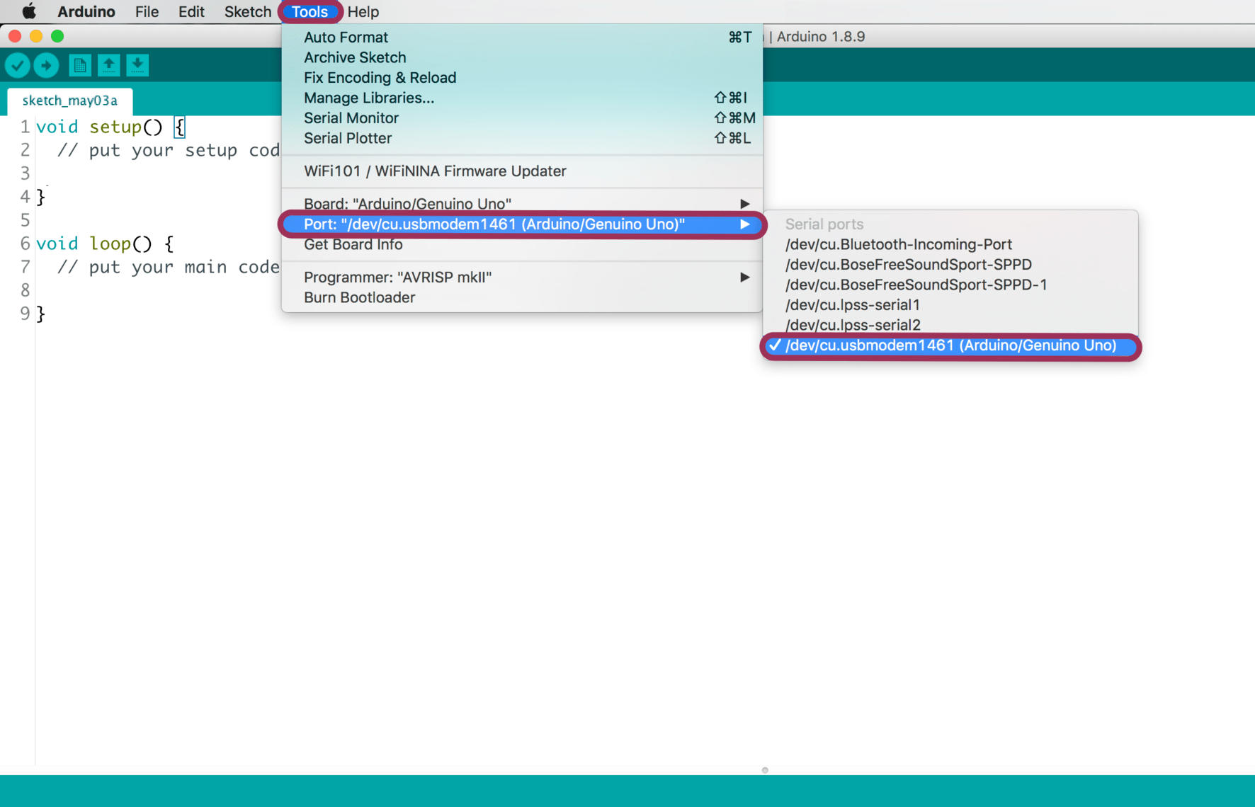
Then, I connected the Arduino Uno board to the USB port of my computer and checked the board type and the serial port.
Tool > Board > Arduino/Genuino Uno
Tool > Board > Arduino/cu.usbmodem1461 (Arduino/Genuino Uno)
After preparing the Arduino IDE, I decided to program an LED Chase effect project.
The components that I used :
Arduino board.
Breadboard.
10 LEDs.
10 Resistors (220Ω).
11 Jumper wires.
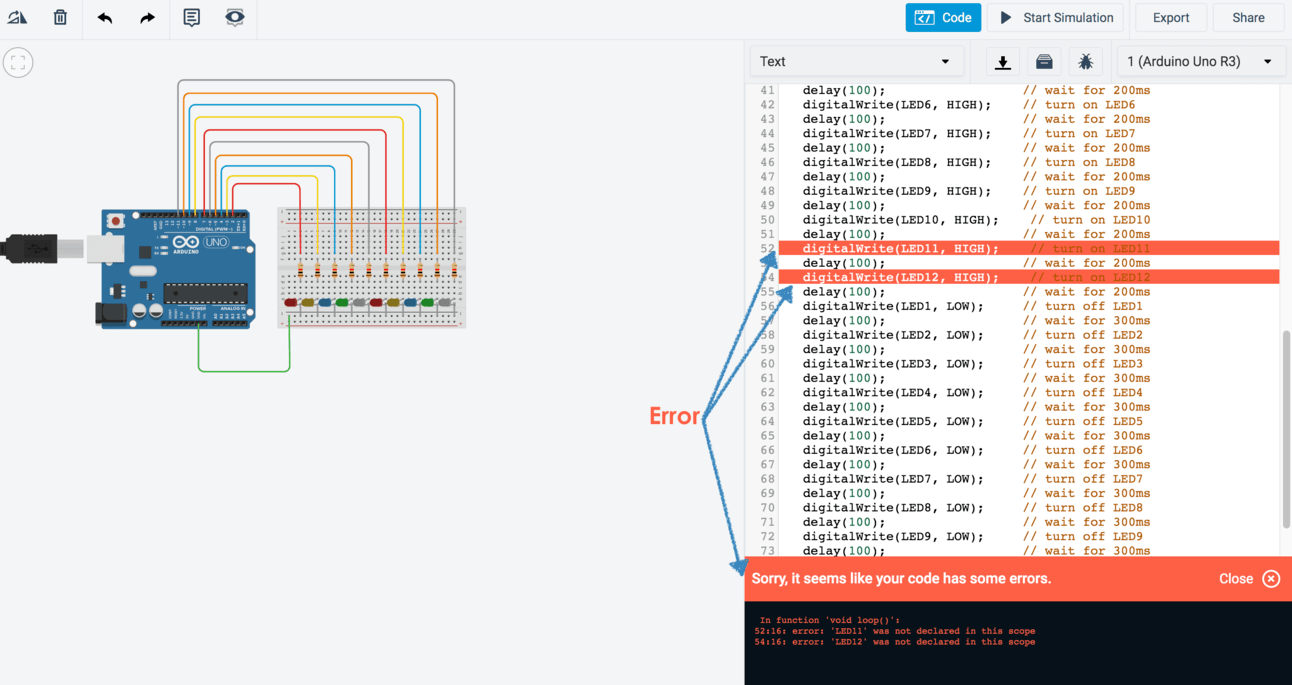
For simulation, I decided to use Tinkercad Circuits simulator. It allows us to test the circuit before actually building it.
After creating the circuit, I selected "Code" button to paste the code then I pressed "Start Simulation" button.

I need to remove LED number 11 and 12 because I just used 10 LEDs.
After the successful simulation, I started the physical connections by wiring up all the components.
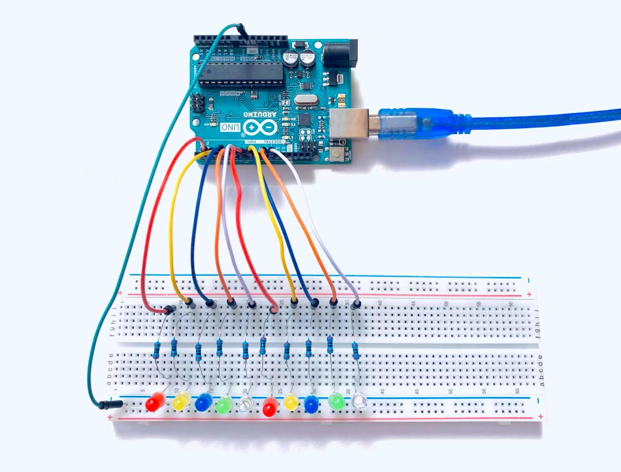
Then, I opened the Arduino IDE and pasted the code in the code area. Next, I clicked on "Save" button then "Upload" button to upload the code to the Arduino board.
The code:
The code:
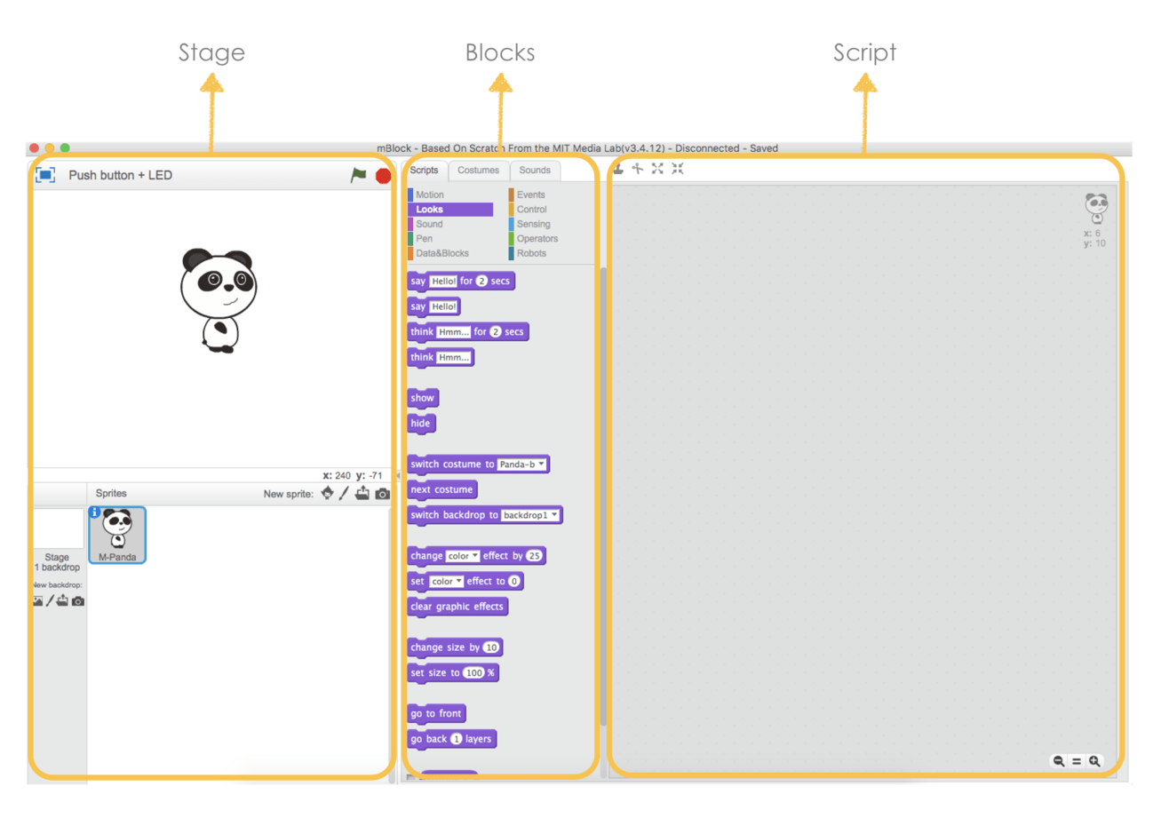
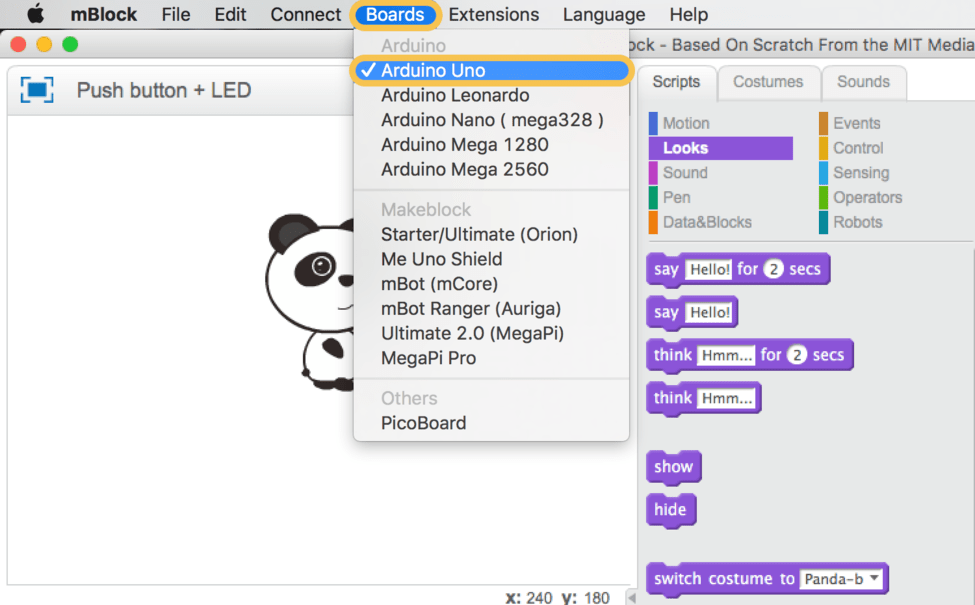
Also, I used mBlock to program the Arduino with Scratch which is a block-based visual programming language.

This is the mBlock platform.It has a simple and easy interface to use specially for kids. It consists of three parts, stage area, blocks area and scripts area.
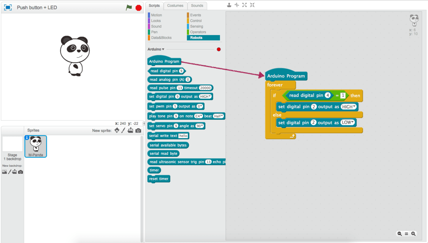
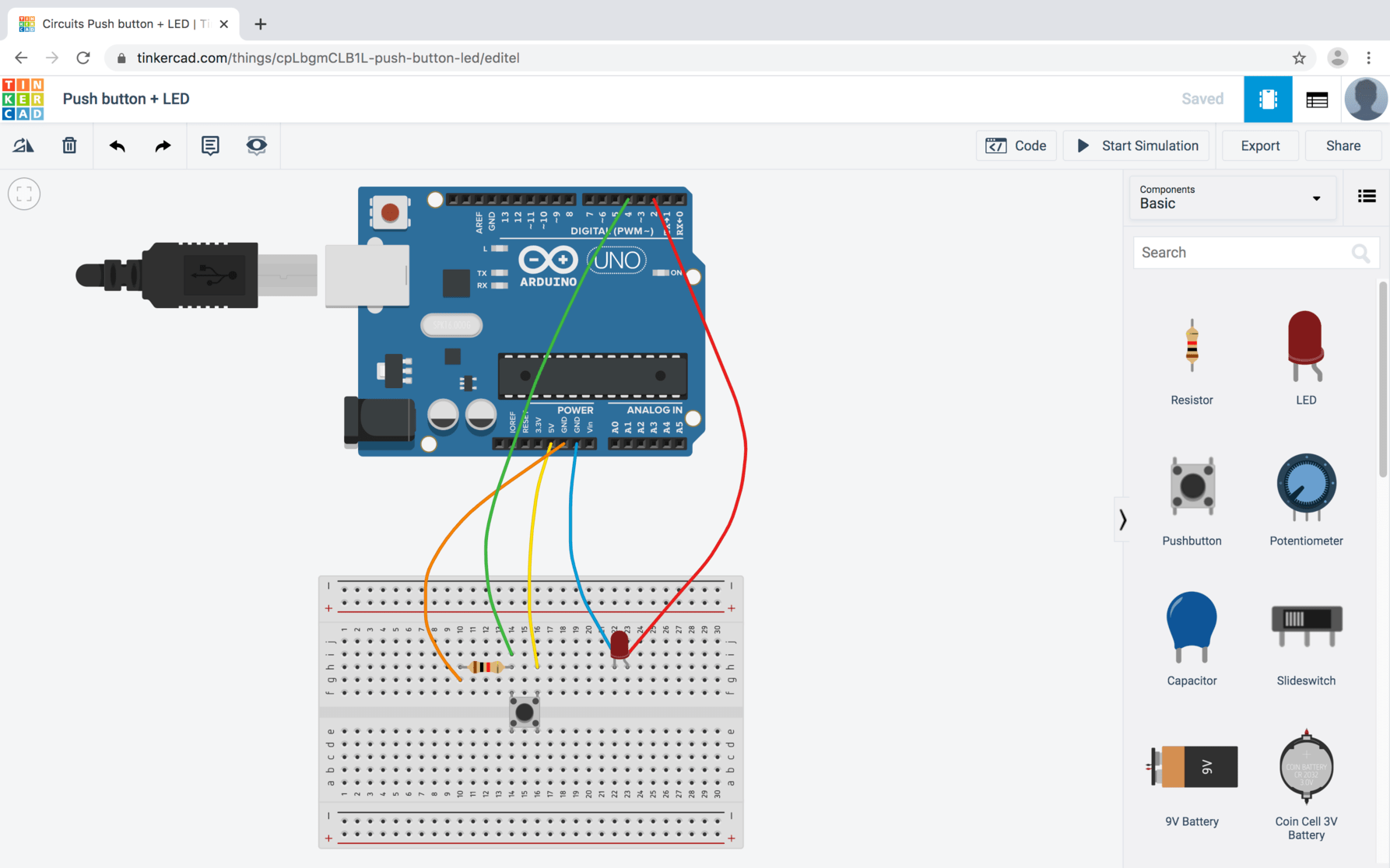
To turn an LED on and off with one push button, I used the following:
Arduino board.
Breadboard.
Push button.
1 Resistor (1K).
5 Jumper wires.
After downloading the mBlock software, I connected the Arduino board to the USB port of my computer and checked the board type by clicking on Board > Arduino Uno.
Next, I dragged the modules blocks that were required for creating the programming from the blocks area to the scripts area.
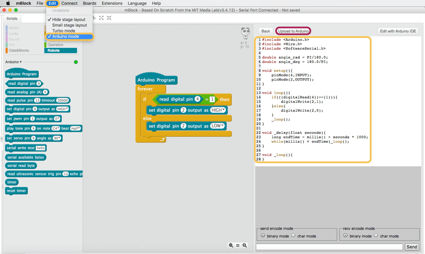
Then, I selected Edit > Arduino mode, to show the Arduino code.
Similar to the previous programming, I used Tinkercad simulator tool before uploading the program to the real board.
After the simulation, I connected the LED and the push button to the breadboard along with some resistors and uploaded the code to the Arduino board.
The code:
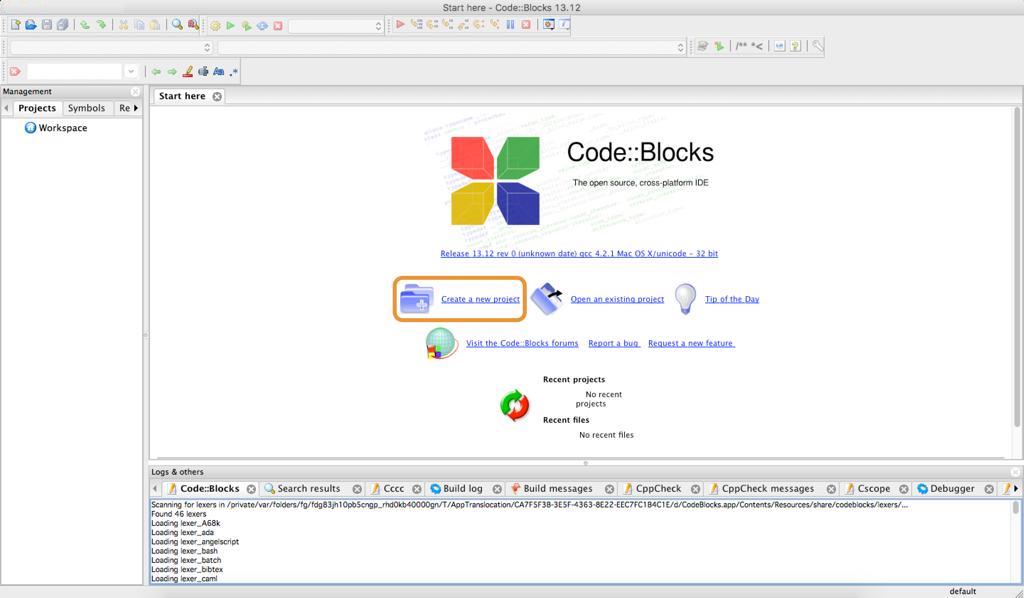
Also, I programmed the PCB using the C language. I used Code Blocks software which is a free, open-source C/C++ integrated development environment (IDE). It can run on Linux, Mac, Windows.

After downloading the software, I selected a new project.
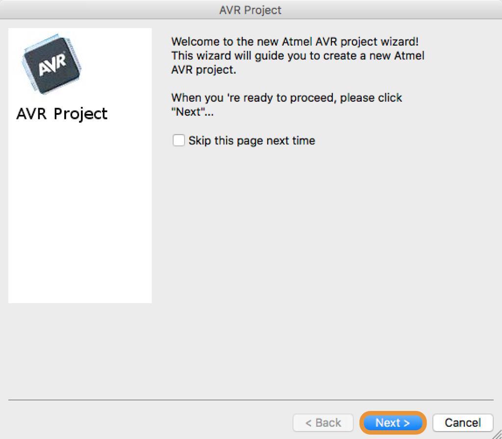
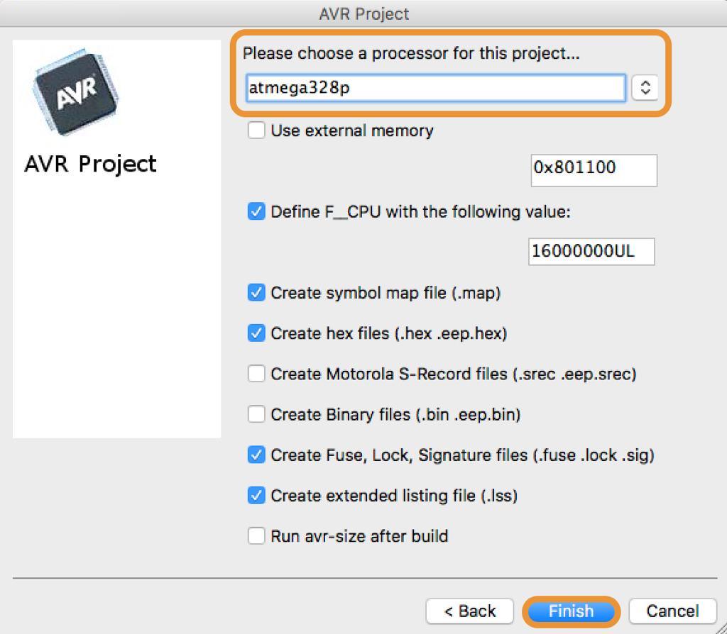
Next, I selected the AVR project.
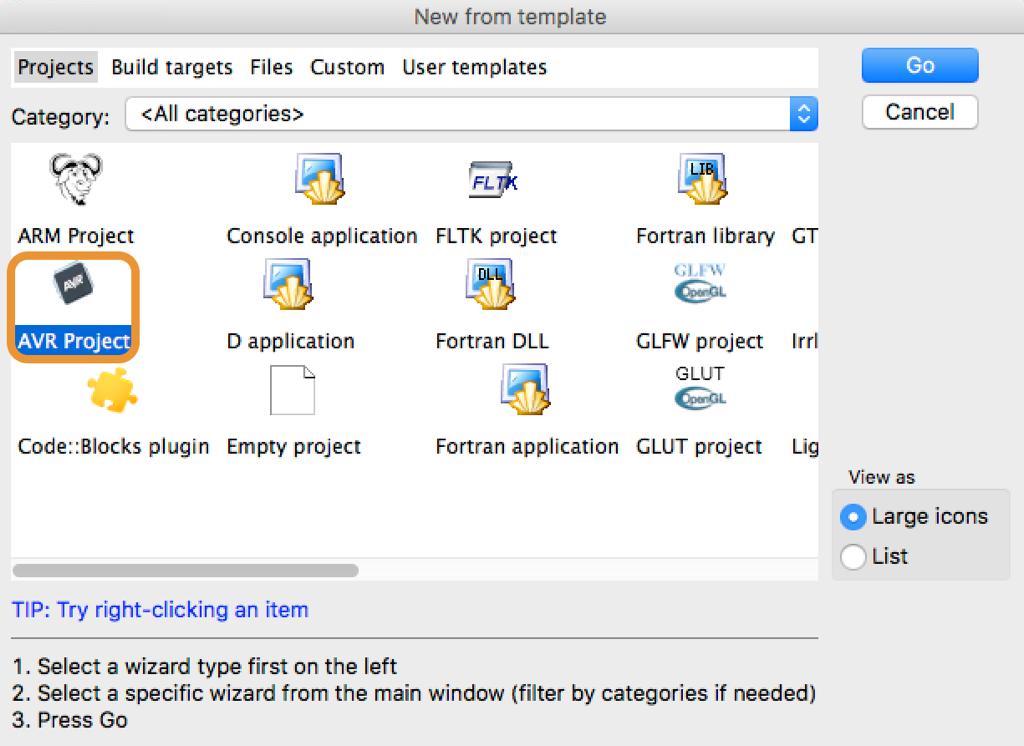
Then, I clicked Next.
After that, I wrote the project title and I changed the destination folder for saving this project.
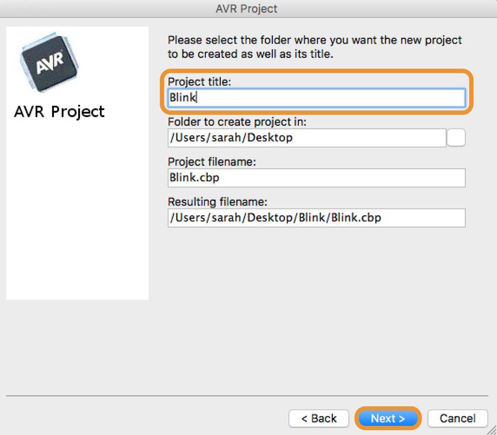
Then, I chose Atmega328p as a processor for the project and I clicked the finish button.
On the left side of the work space, I double clicked on sources and selected main.c.
I wrote the code in the work space.
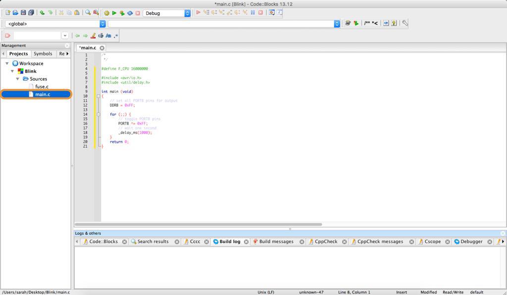
#define F_CPU 16000000
To tell thi chip where all the ports & pins are located :
#include
To use built in delay features for accurate delay :
#include
int main (void)
Set all PORTB pins for output
DDRB = 0xFF;
for (;;) {
Toggle PORTB pins
PORTB ^= 0xFF;
Wait one second
_delay_ms(1000);
return 0;
To compile and build all the files, I clicked on the gear icon located in the menu bar.
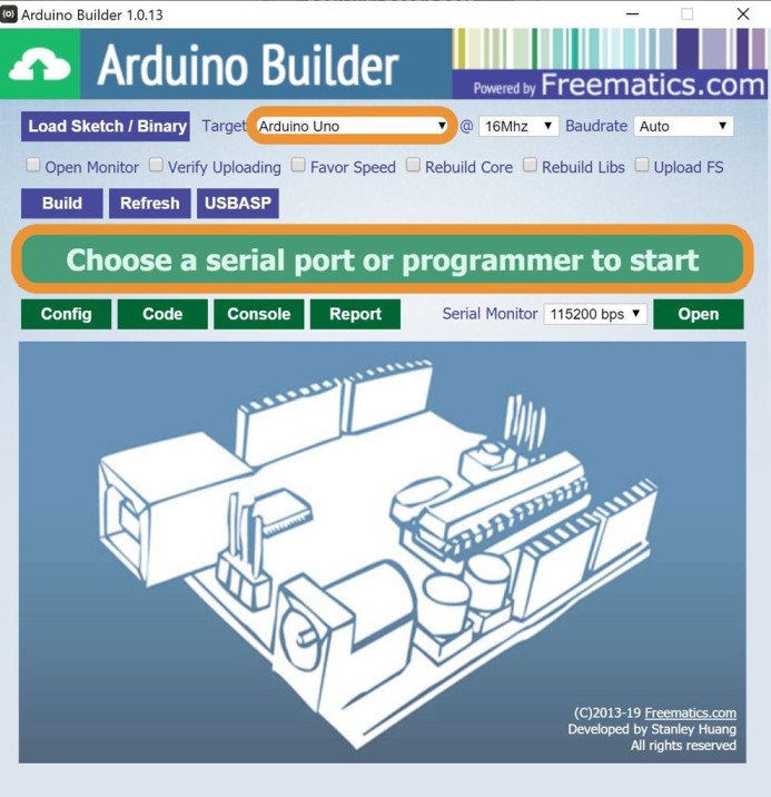
After that, I clicked on the tools from the menu bar then selected on Arduino Builder.I connected the arduino to my PC then I clicked on Load Sketch. I chose the port to upload the code.
After that,I uploaded the Blink code to the PCB via the arduino.
The code: