Tenth assignment
Date
25 Mar 2020
This week's assignment is aimed to modify our board that we have designed before, by adding a sensor and testing it.
I used the Arduino board temporarily instead of a new PCB, because of the curfew situation.
There are many types of input devices, such as ultrasonic sensor, motion Sensor, pressure Sensor and IR Sensor.
I decided to test two of the input devices :
LDR
Ultrasonic
LDR
What is LDR ?
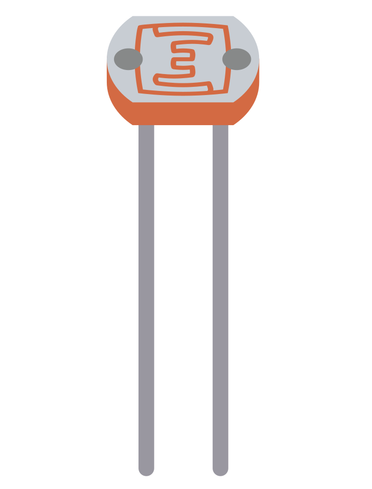
A Light dependent Resistor known as a LDR, is a variable resistance that changes depending on the intensity of light that falls on its top surface. It has other names : photoconductor, photoresistor and photocell.
This resistance has an Inverse relationship with the light, when the light amount increases, the value of the resistance will decrease, and vice versa.
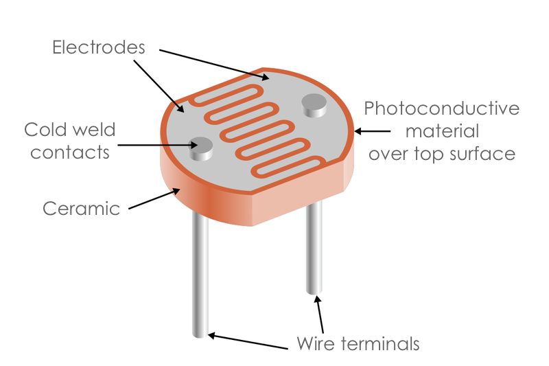
The main parts of LDR :
There are many uses of LDR in everyday Life, for example:
Alarm clocks
Street lights
Light intensity meters
Burglar alarm circuits
To start, I Identified the components that I need to turn LED on and off through LDR.
The components list :
1 x Arduino board
1 x Breadboard
7 x Jumper Wires
1 x LDR sensor
1 x LED
1 x 10k Ω Resistor
1 x 220 Ω Resistor
The 10k resistor used along with the LDR to create a voltage divider circuit. The LDR varying resistance is converted to a varying voltage which will be used by the analog pin.
Before connecting the components, I created a virtual circuit by using the Tinkercad simulator to check the connection and the code and avoid mistakes in the real circuit.
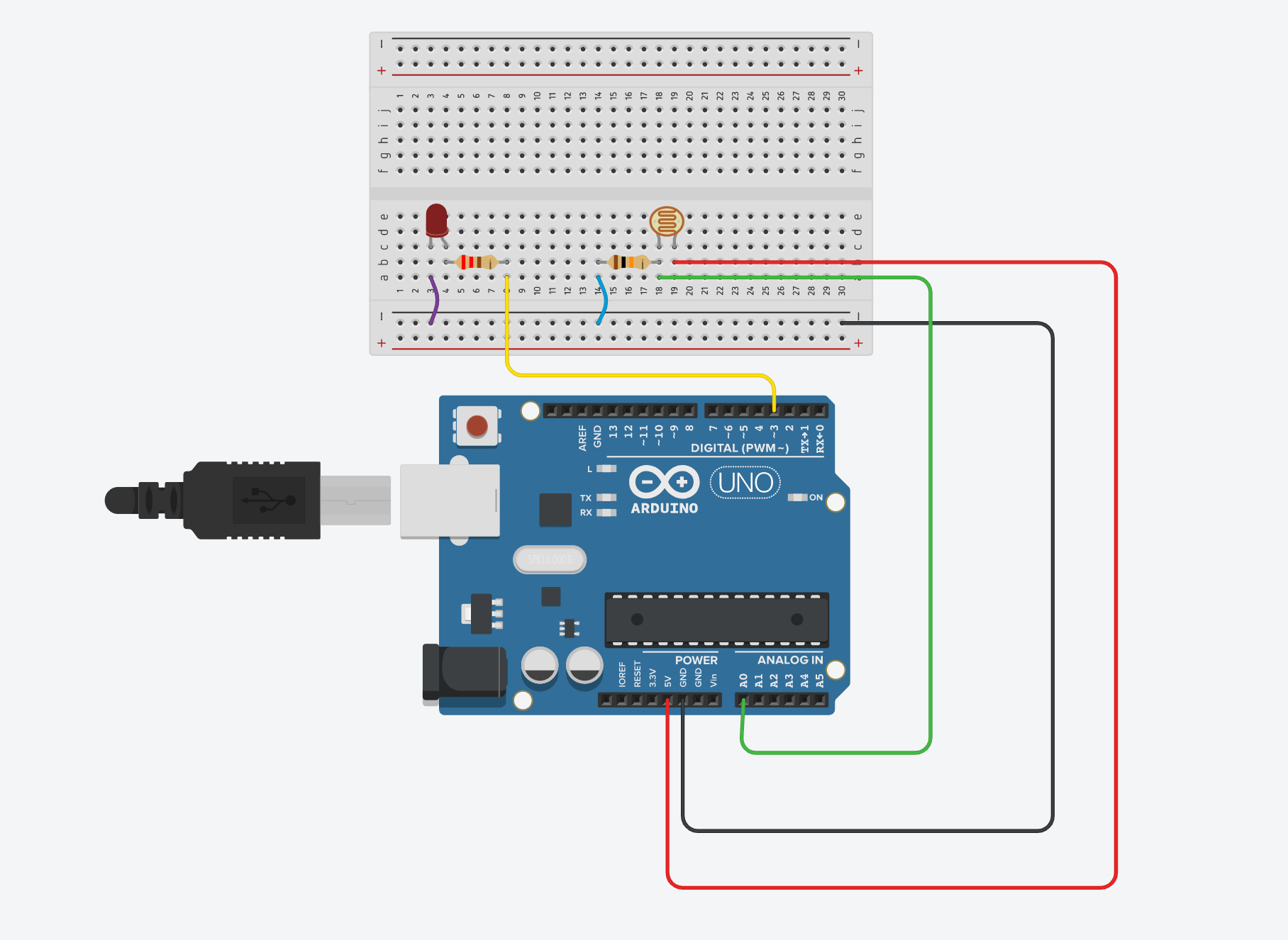
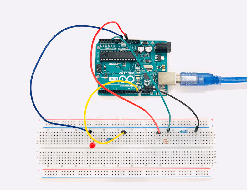
After the simulation process, I started wireing up the co mponents by placing the LDR on the breadboard first. Then, I connected one of the LDR pins with the 10k Ω resistor to the analog input (A0) for reading the approximate value of the light levels.
The other leg off the LDR connected to the +5v. Next, I attached the 220 Ω resistor to the LED anode leg and the other resistor leg to the digital pin 13 of the Arduino. Lastly, the LED cathode leg connected to GND.
Next, I opened the Arduino IDE and uploaded the code. In this test, the LDR will work as a switch. If I cover the photocell to be in darkness, the LED will turn on and if I keep the light falling on its surface, the LED will turn off.
Now that everything is ready, It is time for my favorite part, coding !
PROGRAMMING
Define the LED pin and the LDR pin.
write the serial begin function which is used to set the data rate in bits per second (baud) for serial data transmission.
Initialize the pin mode by making the LED the output and the LDR the input.
Use the analog read function to read the value of the LDR.
Use If else statement.
Display the status.
const int ledPin = 13;
const int ldrPin = A0;
In the void setup() section:
Serial.begin(9600);
pinMode(ledPin, OUTPUT);
pinMode(ldrPin, INPUT);
In the void loop() section:
int ldrStatus = analogRead(ldrPin);
If the status is less than or equal 300, the LED will turn ON.
if (ldrStatus <=300) {
digitalWrite(ledPin, HIGH);
Serial.println("LDR is DARK, LED is ON");
Else, the LED will turn off and display the status.
} else {
digitalWrite(ledPin, LOW);
Serial.println("---------------")
The code :
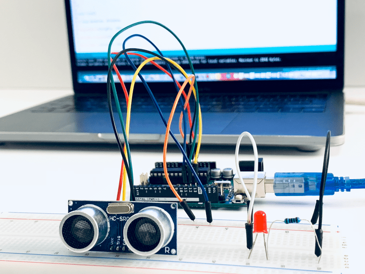
Ultrasonic Sensor
What is Ultrasonic ?
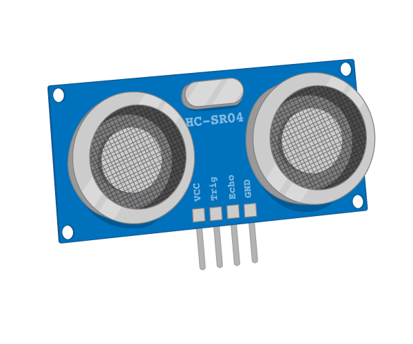
An Ultrasonic sensor is a tool that measures the distance by sending an ultrasonic wave at a specific frequency and receiving the reflected wave from the object.
Ultrasonic sensor has four pins :
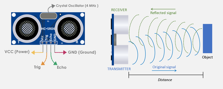
VCC pin is connected to +5V.
Trig is an Input pin that sended a signal to trigger the Ultrasonic sound pulses.
Echo is an Output pin that sended a signal back after detecting the object.
GND pin connected to the ground.
The distance can be calculate using this formula :
There are many applications of the Ultrasonic sensor in daily Life, for example:
Vehicle detection for car wash.
Anti-Collision Detection.
Human Presence Detection.
Pallet Detection with Forklifts.
I determined the components that I need to turn LED on or off by detecting the distance through the Ultrasonic sensor.
The components list :
1 x Arduino board
1 x Breadboard
8 x Jumper Wires
1 x Ultrasonic sensor
1 x LED
1 x 1k Ω Resistor
To create a successful Arduino experiment, I started making the circuit using the Tinkercad simulator by dragging the components and connecting them to the breadboard and the Arduino board.
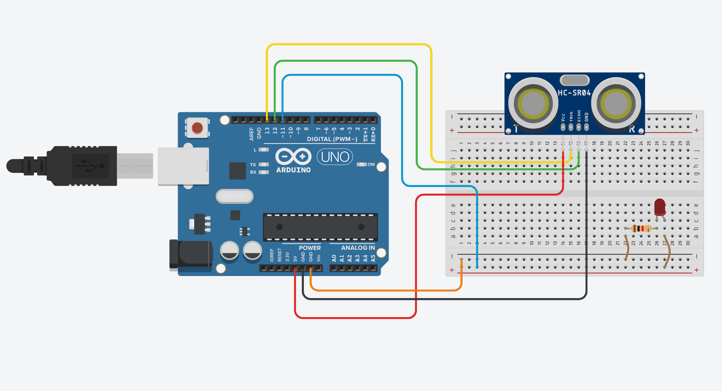
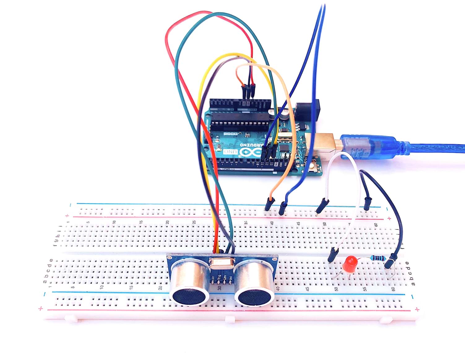
After the simulation, I connected the physical components together. I started by placing the Ultrasonic to the breadboard. Next, connected the Ultrasonic HC-SR04 Pins distance sensor as the following :
Then, I attached the 1k Ω resistor to the LED cathode leg and the other resistor leg to the negative rail of the Arduino. Then, the LED anode leg connected to the positive rail.
PROGRAMMING
To write the code:
Define pin numbers for the trig, echo and LED.
Write the serial begin function to show the result in the serial monitor.
Define the pin mode by making the Echo as input, the LED and the Trig as output.
Defined variables by using
longfunction which is extended size variables for number storage.Set the Trig pin on a low state for 2 microseconds to make it clear.
Generate the ultrasound wave I set the Trig pin on high state for 10 microseconds.
Read travel time by using
pulseInfunction and put that value into the variable “duration”Calculate the distance by by the following equation:
Use If else statement :
Print the value of the distance on Serial Monitor.
Use delay() which is a blocking function that prevents a program from doing anything else until that particular task has completed.
int trigPin = 13;
int echoPin = 12 ;
int led = 11 ;
In the void setup() section:
Serial.begin (9600);
pinMode(trigPin, OUTPUT);
pinMode(echoPin, INPUT);
pinMode(led, OUTPUT);
In the void loop() section:
long duration, distance;
digitalWrite(trigPin, LOW);
delayMicroseconds(2);
digitalWrite(trigPin, HIGH);
delayMicroseconds(10);
digitalWrite(trigPin, LOW);
duration = pulseIn(echoPin, HIGH);
distance = (duration/2) / 29.1;
The duration is divided by two because the sound has to travel the distance twice then divide it by 29.1 which is the speed of sound.
If the distance is less than 10 cm, the led will turn on.
if (distance < 10)
if{ digitalWrite(led,HIGH);
Else, the led will turn off.
else {
digitalWrite(led,LOW);
Serial.print(distance);
Serial.println(" cm");
delay(500);
The code:
After all the exercises that I tried with the arduino board, finally the lockdown ended. I made my PCB with Atmega atmega328p microcontroller
What is ATMEGA328P microcontroller?
Atmega 328p from Atmel is a high performance, low power controller from Microchip. It is an 8-bit microcontroller based on AVR RISC architecture. It is the most popular of all AVR controllers as it is used in ARDUINO boards.
I had to read the Datasheet to know more about it.
Atmega 328p features :
High Performance, Low Power AVR® 8-Bit Microcontroller.
Microcontroller that is pre-loaded with the Arduino UNO 16MHz bootloader.
Advanced RISC Architecture.
Digtal 14 Pin I\O.
Analog 6 Pin input.
131 Powerful Instructions – Most Single Clock Cycle Execution.
32 x 8 General Purpose Working Registers.
Fully Static Operation.
Up to 20 MIPS Throughput at 20 MHz.
On-chip 2-cycle Multiplier.
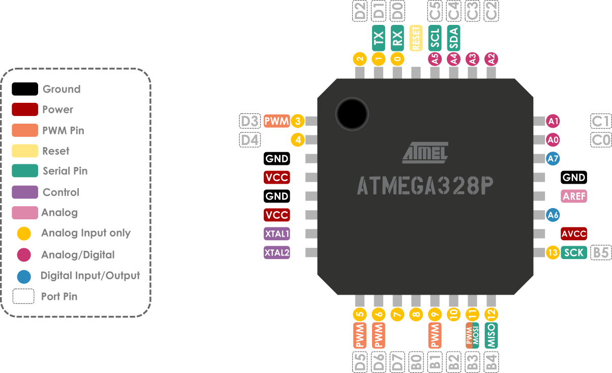
Atmega 328p pins :
Pinout diagram is shown in below
RFID
What is RFID Reader?
RFID means radio-frequency identification, a technology used for electronic and wireless identification of objects, humans and animals. It uses electromagnetic fields to transfer data over short distances.
Specifications:
Input voltage: 3.3V
Frequency: 13.56MHz
Communication : SPI, I2C protocol, UART
Maximum Data Rate: 10Mbps
Read Range: 5cm
How does it work ?
Two-way radio transmitter- receiver, the reader, that sends a signal to the tag and reads its response.
RFID pinout
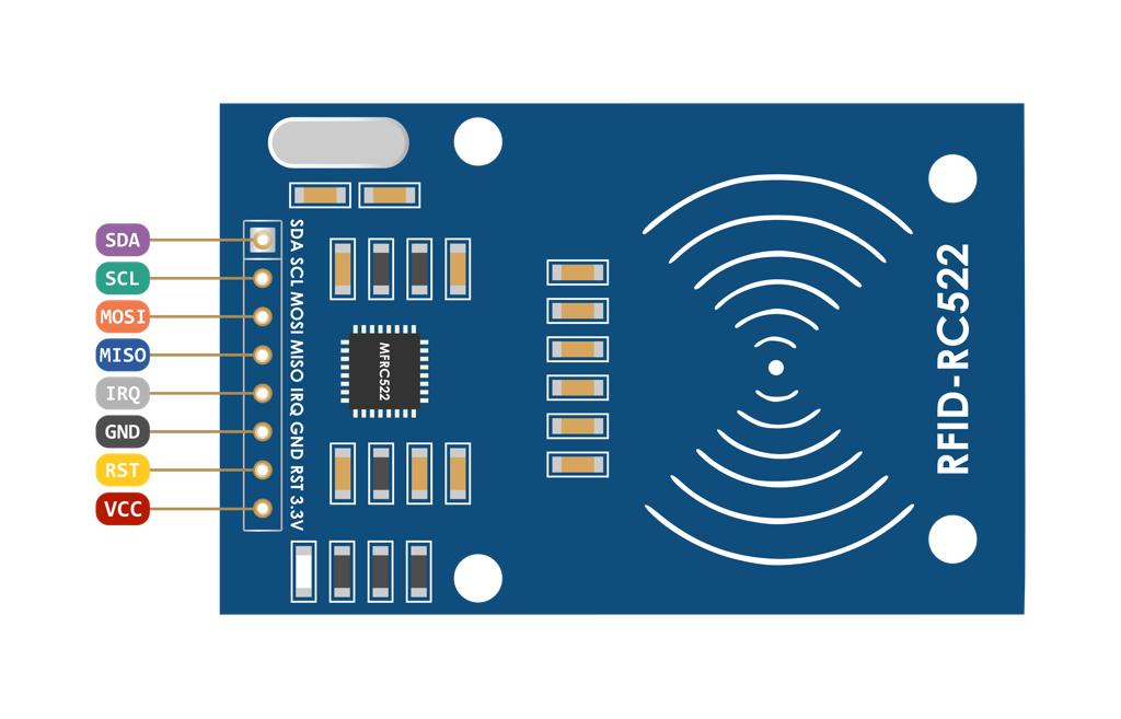
VCC supplies power for the module.
RST is an input for Reset and power-down.
GND is the Ground Pin.
IRQ is an interrupt pin that can alert the microcontroller when RFID tag comes into its vicinity.
MISO / SCL / Tx pin acts as Master-In-Slave-Out when SPI interface is enabled.
MOSI (Master Out Slave In) is SPI input to the RC522 module.
SCK (Serial Clock) accepts clock pulses provided by the Arduino.
SS / SDA / Rx pin acts as Signal input when SPI interface is enabled.
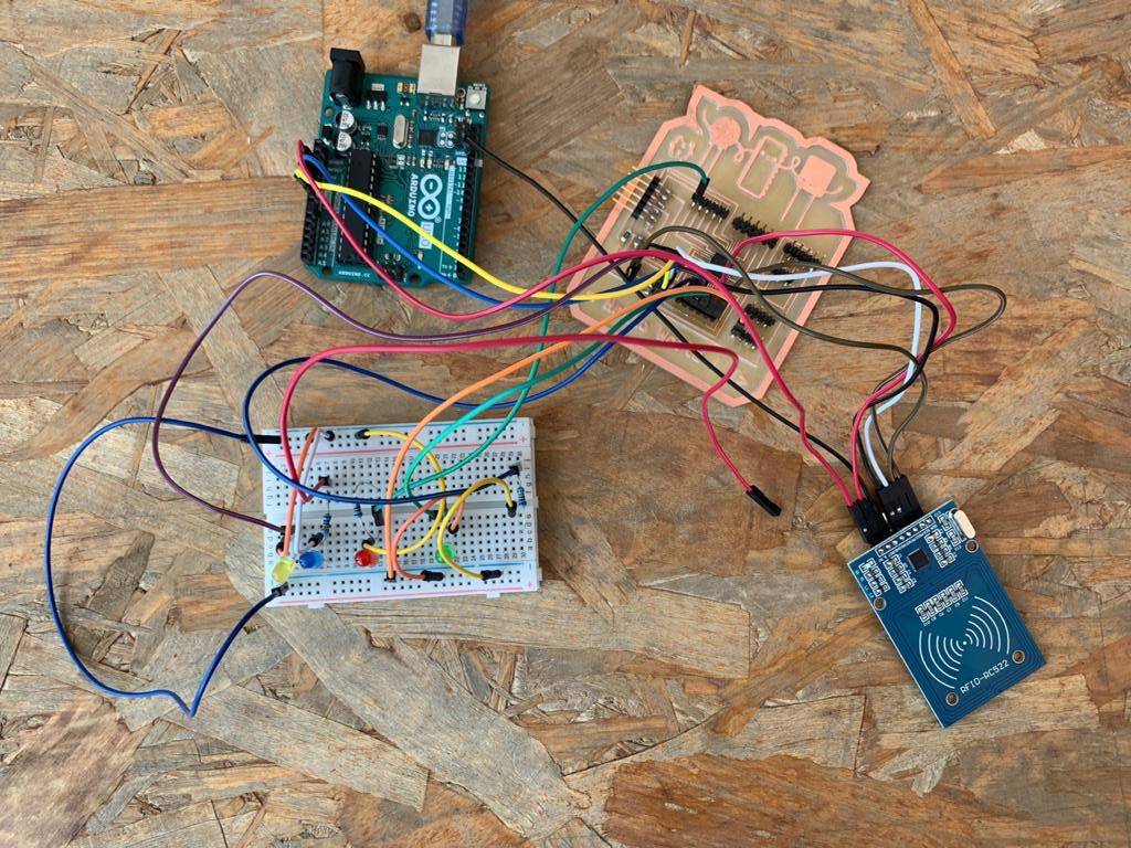
Each RFID card has a unique ID to present a specific command. I used a simple code to prepare RFID Cards and test it.
Components
Arduino UNO
MFRC522 RFID Reader
RFID Tags
Bread Board
LEDs
PROGRAMMING
I followed some steps to write a code to light up an LED when the right tag will be detected.
Include the MRC522 Library
#include
Include the SPI Library to communicate via SPI with the Module.
#include
Define RFID Module SDA Pin that connected to the pin 10
#define SS_PIN 10
Define RFID Module RST Pin that connected to the pin 9
#define RST_PIN 9
Define LEDs that connected to the pins
int LED_A = 8;
int LED_B = 7;
int LED_C = 6;
int LED_D = 5;
int LED_E = 4;
Initialization of the library using the ARDUINO pins declared above.
MFRC522 rfid(SS_PIN, RST_PIN);
In the the setup()
Opens up the communication to the serial monitor in Arduino IDE
Serial.begin(9600);
SPI.begin();
Initialize MFRC522
rfid.PCD_Init();
Initialize digital pin LEDs as an output
pinMode(LED_A, OUTPUT);
pinMode(LED_B, OUTPUT);
pinMode(LED_C, OUTPUT);
pinMode(LED_D, OUTPUT);
pinMode(LED_E, OUTPUT);
In the the loop()
Look for new cards to select one.
if (!rfid.PICC_IsNewCardPresent() || !rfid.PICC_ReadCardSerial())
return;
MFRC522::PICC_Type piccType = rfid.PICC_GetType(rfid.uid.sak);
Check is the PICC of Classic MIFARE type
if (piccType != MFRC522::PICC_TYPE_MIFARE_MINI &&
piccType != MFRC522::PICC_TYPE_MIFARE_1K &&
piccType != MFRC522::PICC_TYPE_MIFARE_4K) {
Serial.println(F("Your tag is not of type MIFARE
Classic."));
return;
Store NUID into nuidPICC array
String strID = "";
for (byte i = 0; i < 4; i++) {
strID +=
(rfid.uid.uidByte[i] < 0x10 ? "0" : "") +
String(rfid.uid.uidByte[i], HEX) +
(i!=3 ? ":" : "");
}
strID.toUpperCase();
Serial.print("Tap card key: ");
Serial.println(strID);
check the card to light up the LED
if (strID.indexOf("E2:F6:07:2E") >= 0) {
digitalWrite(LED_A, HIGH);
} else {
digitalWrite(LED_A, LOW);
And make this step for all the LEDs and tags.
After the code was checked, I uploaded it to the PCB.
Any Problem ?
While working on different experiments using the Arduino, It became difficult for me to recognize the resistors values because it mixed up in the kit box.
What is a Resistor?
Resistors are the passive components that used to reduce the flow of electric current in the electrical circuits.
What is a Tolerance ?
It is the percentage of error in the resistance value that says how much more or less one can expect a resistor's actual measured resistance to be from its stated resistance.
The Ohm’s Law
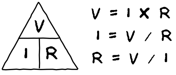
This Law describes the relationship between the electrical current, voltage and resistance. Resistance is equal to Voltage divided over current.
HOW TO READ RESISTOR COLOR CODES ?
I used this chart to find the Resistor's value.
Also, this website helped me to calculate the value by selecting the number of bands then determining their colors.
Click here
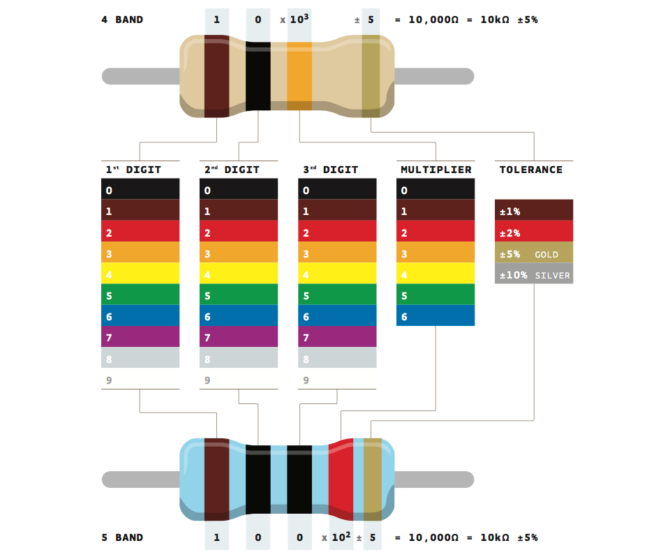
Resistor has either 4 or 5 bands with different colors. Each color correlates to a specific number.
To read the Resistor value, we need to determine the gold(5%) or silver(10%) side which indicates the tolerance and start reading the resistor from the opposite side.
In the 4-band Resistor:
The first two bands represent the first two digits of the Resistor.
The third band represents the multiplier(the power of ten).
The fourth band specifies the tolerance.
In the 5-band Resistor:
The first three bands represent the first three digits of the Resistor.
The fourth band represents the multiplier(the power of ten).
The fifth band specifies the tolerance.
DOWNLOAD FILES :
Code files:
Resources: