Computer Controlled Machining
Test runout, alignment, speeds, feeds, and toolpaths for your machine.
Document your work (in a group or individually).
Individual project:
Make (design + mill + assemble) something big.
Learning outcomes:
Demonstrate 2D design development for CNC production.
Describe workflows for CNC production.
For this week's assignment, It was required to design and fabricate something BIG! by using the CNC machine, one of my favorite machines I used to worked with it.
When I start working with the CNC?
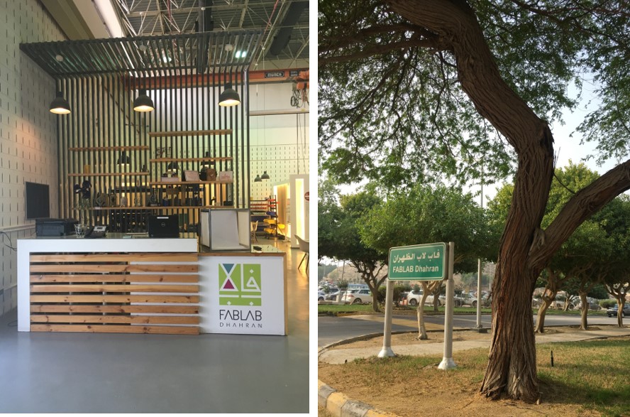
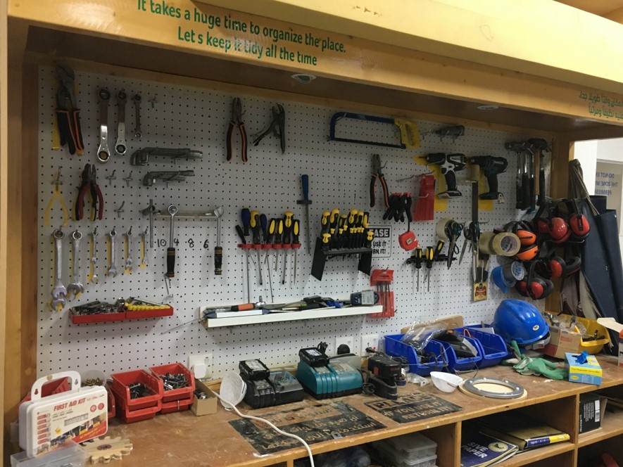
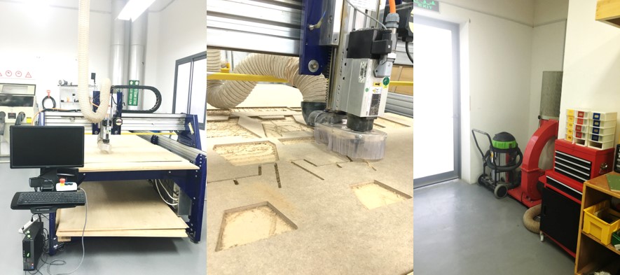
The story staring from this place (Fab Lab Dhahran)
I used to work with the CNC Machine since 2015 until 2019, after that our FabLab Dhahran shutdown. I did many projects in that period, some are personal projects and others as my duty as 2d facilitator and mentor helping to create the first prototype. Some of the projects I had participated in as a mentor are the Fabhouse, Newton Telescope, Prototyping week 2016 and 2017, and many others projects. Throw these projects I learn a lot about the controlled machining and still I want to learn more about it, especially how to use it to fabricate 3d designs.
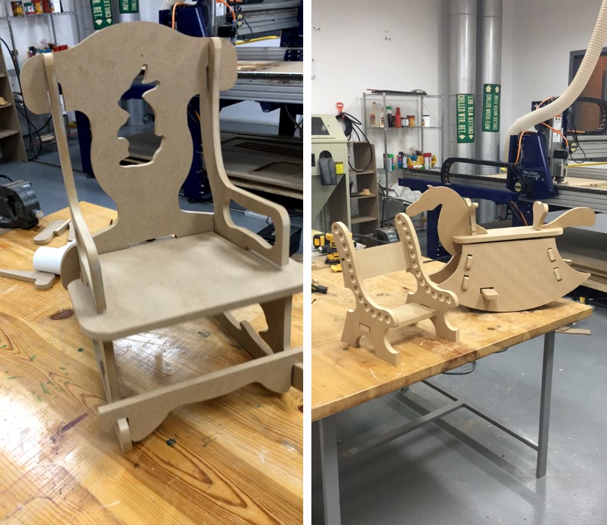
Here are the first real applications while I was trying to practice the CNC 2018
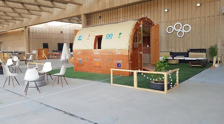
Fabhouse one of my favorite community project with Fablab team.
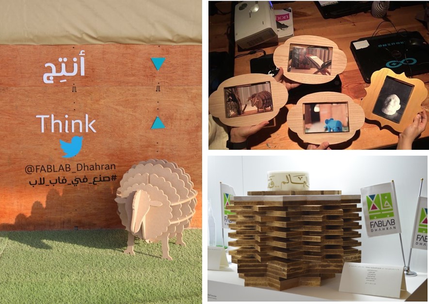
The sheep was made by the volunteers I was supervisor them in summer 2018, the photo frames were also made by the CNC for a photography exercise while we were at photography month at Fablab. the side table was one of the first prototypes with CNC machine, it was made at 2015 Gifted summer program.
First Prototype for Newton Telescope base.
What is the CNC?
Computer Numerical Control machine is a high precision tool that's computer-controlled and makes repeated, accurate movements. It does so by taking computer-generated code and converting it with software to electrical signals.
What materials can I use?
MDF, plywood, solid wood, foam, and plastics
The Advantages of CNC Machines:
- Machining is accurate.
- Time taken to perform a job is very less.
- Safe to operate.
- Number of operators required to operate a machine are reduced.
- No possibility of human error.
- Reliable.
- Even very complex designs can also be made.
- Low maintenance required.
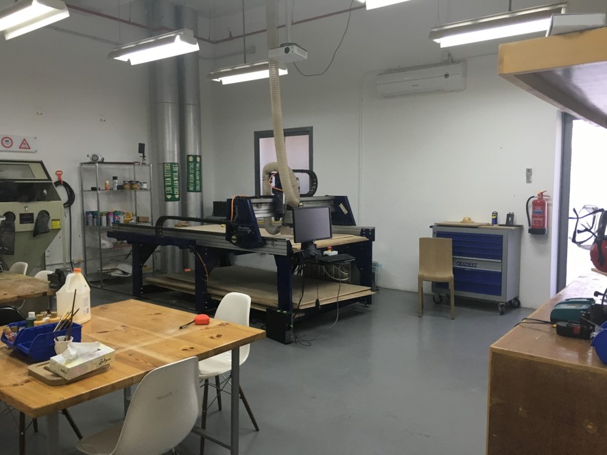
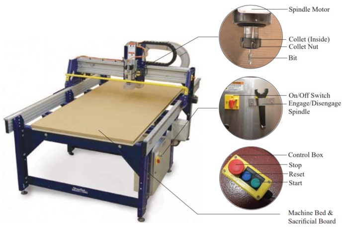
We will use ShopBot PRSalpha 120-60 CNC machine, from Shopbot, an amirican CNC machine.One of the best for and common in different educatinal filed, the PRSalpha series tools deliver rapid transit speeds of 1800 inches per minute and cutting speeds of up to 600 inches per minute.
Easy to configure and re-configure, learn and use, the PRSalpha CNC delivers affordable, full-production performance in digital fabrication of wood, plastic, aluminum, and other materials.
Specifications of ShopBot PRSalpha 120-60
| Cutting speed | 10 in/s (250 mm/s) |
| Jogging speed | 30 in/s (760 mm/s) |
| Move speed (X, Y) | 12 in/s (305 mm/s) |
| Move speed (Z) | 6 in/s (153 mm/s) |
| Positioning speed (X, Y) | 30 in/s (760 mm/s) |
| Positioning speed (Z) | 15 in/s (380 mm/s) |
| Step resolution | 0.0004" (0.010 mm) |
| Positional repeatability | 0.002" (0,051 mm) |
| Linear cutting power | 150 lbs (68kg) |
| X- and Y-axis drive system | Rack and pinion |
| Z-axis drive system | Rack and pinion |
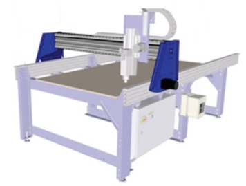
The main parts of ShopBot PRSalpha
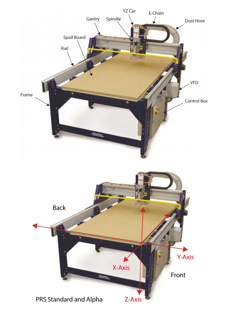
Table Frame the two long aluminum extrusions on each side are called table sides.
A top the sides are the rails, which create the path of travel for the X-axis.
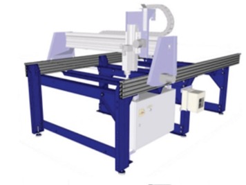
The gantry consists of an extruded aluminum beam, which has been fitted with V rails (for wheel bearings) and gear rack.
This forms the path of travel for the Y-axis. The blue plates on either side of the gantry are referred to as end plates.
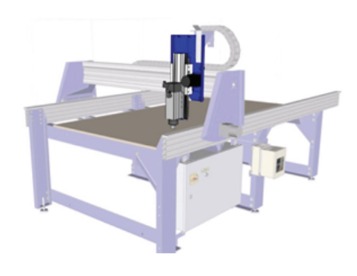
The YZ car moves across the gantry, and controls the height of the cutter head (either a router or high-speed spindle, depending on the tool)
The control box is the “brain” of the machine and contains a control board, motor drivers, and other electronic components that allow the tool to move with precision, accuracy, and power. It connects to the PC through a single USB cable.
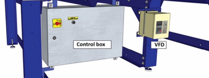
The variable frequency device (VFD) is controls speed and power for the spindle. The control box provides the VFD with on/off signals, but speed is controlled through an RPM controller unit, which connects to the PC through a separate USB cable.
PRSAlpha Guide
The main software for operating:
ShopBot Control download here.
VCarve Pro download here.
for product development such as Illustrator, Inventor, Fusion 360, Ownshape, Inkscape, atc.
Safety while using ShopBot PRSalpha!
safety check list for CNC
Safety for CNC ShopBot
Stopping ShopBot PRSalpha in an Emergency
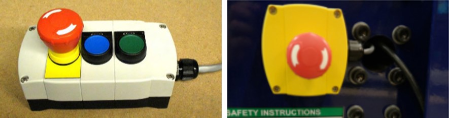
There are two ways to manually stop the router when it is running: clik on space bar or on emergency stop (E-stop). kicking the space bar is the preferred method for quickly stopping the router by pressing the Spacebar the machine will:
- Stop gantry movement.
- Bring the spindle to a stop quickly.
- Allow the job to be easily restarted.
- Using the E-Stop will:
- Stop gantry movement.
- Kill power to the spindle. It will slowly coast to a stop and drop towards the table.
- Cause the router will lose its known position, and will need to be reset.
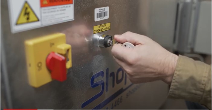
What is the Safety Interlock Key do?
The safety interlock key must be inserted in the machine to enable the spindle. The key is attached to the spindle wrench to remind you.
Always remove the key before changing end mills.
- Removing the key will disable the spindle.
- Also you can press on the red button to stop the machine.
What are the cutting tools used with ShopBot PRSalpha?
Cutting tools have two parts, the shank and flute.
End mills router bits
- These bits are designed to cut while moving sideways through the material.
- A regular end mill has a flat end, and is used for cutting at surfaces.
- A ball end mill has a hemispherical end, and is used for 3D machining and finishing passes.
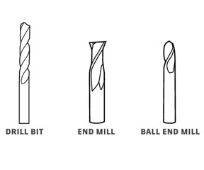
Drill bits
- These are the same bits used in a hand drill or drill press.
- They are only for drilling holes, and only work when moving straight down
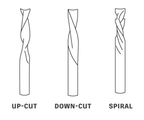
For more about bits:
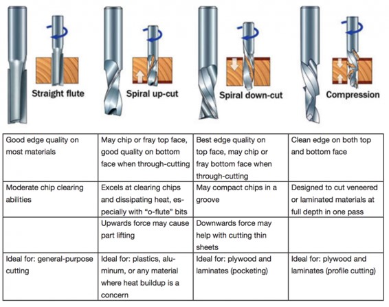
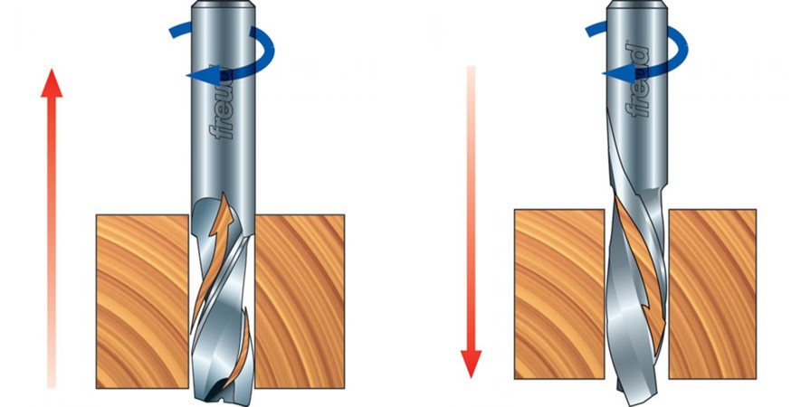
Upcut = clean bottom of the workpiece. Downcut = clean the face of the workpiece.
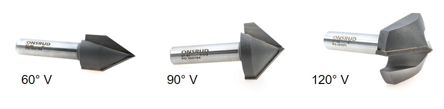
60° V, 90°V, 120° V Flute for V-Grooving or Beveling Edges for Wood. T he tols designed for V grooving or beveling edges of parts, and to cut a wide variety of wood products to produce a clean edge.
Spiral Router Bits vs Straight Router Bits
Individual Project
Make design, mill, assemble sothing big.
What I will do?
- Create 2D design.
- Transfer the toolpaths to the CNC Control PC.
- Generate toolpaths for CNC cutting.
- Export toolpaths for CNC cutting.
- Load toolpaths into the CNC control software.
- Prepare the machine with correct tooling and material to cut.
- Run the CNC.
Create 2D design
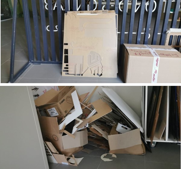
I Started thinking how to organized our uesd matriels,so I started explore for practical sulotions.
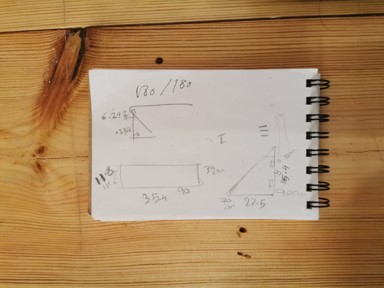
I sktechd the idea, and I kept in mine to match the others orgniser that already in the lab.
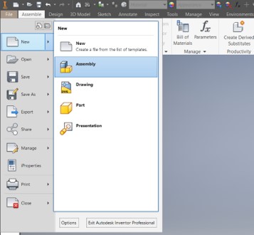
After I opened the I nventor, I cliked in new >>> Assmbly design.
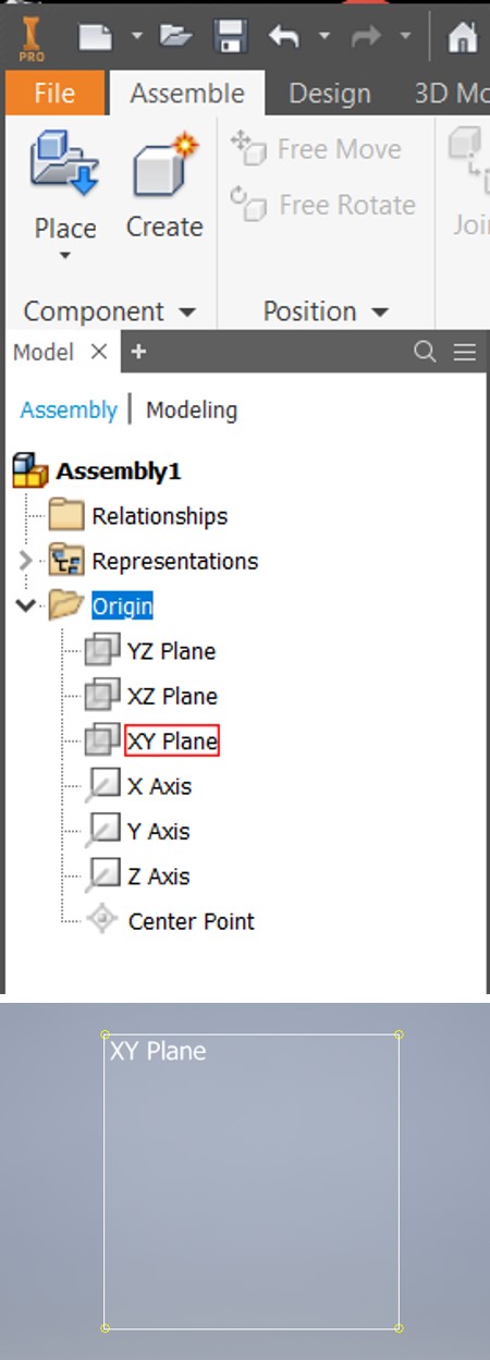
I selected the XY plane, to desing over.
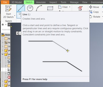
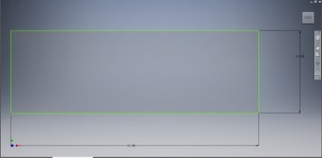
By using the Line tool, I designed the parts, based on the matirila thickness I'll use, It is 15mm plywood or MDF.
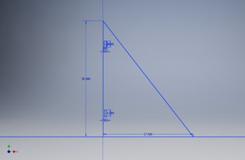
Based on my previos sckth, I desinged the first part.
I kept in my mind the matirila thickness, I drow the slots to joint the parts togothers.
This par one of the important parts, it will help me to support the box and to joint the sides togother.
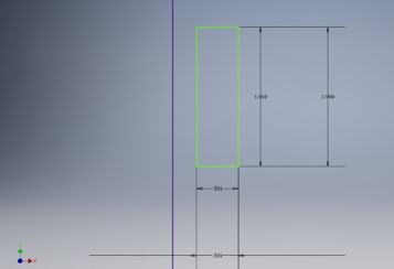
I designed the tenon based on the slots and material thickness.
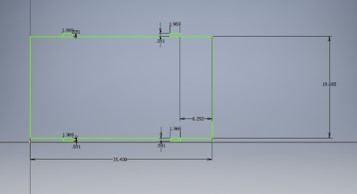
last piece it I will use is to do the sections inside the scrap box, for now I need 3 sections for 3 diffrent matirilas, wood, acrylic, and paper.
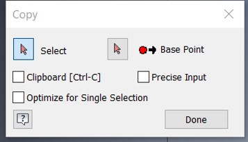
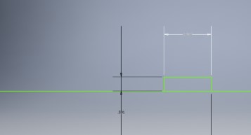
From modifiy panle To copy some parts, I used copy tool, I selected the geometry, the I clicked on base point, by moving my hand the shape will copied.
I copied the parts I need.
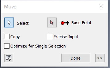
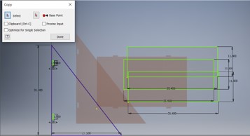
After slected all the geometry from modifiy panle I uesed Move tool, by slected the base point that allows us to freely move the shape from, to any place in the sktech.
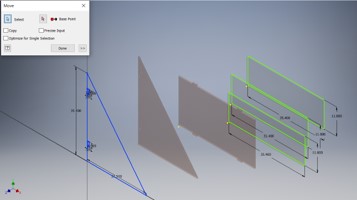
The geometry slected, and moved.
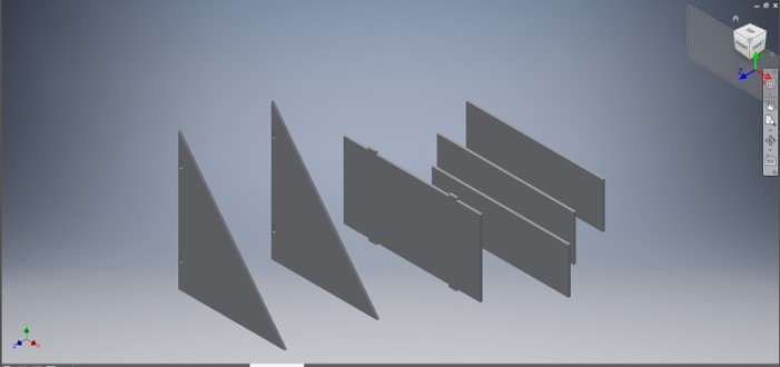
The design is ready.
Transfer the toolpaths to the CNC Control PC. simply shave it as .Dwg or follow the instractions here as I did here in week 3 under the prepare file for laser cutter.
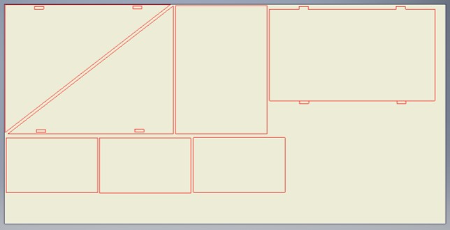
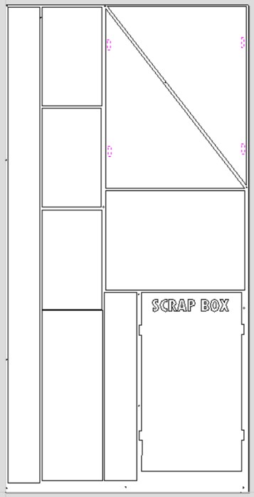
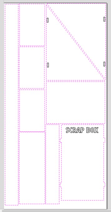
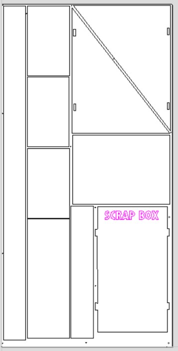
It’s important to nest all the parts and avoid materials waste.
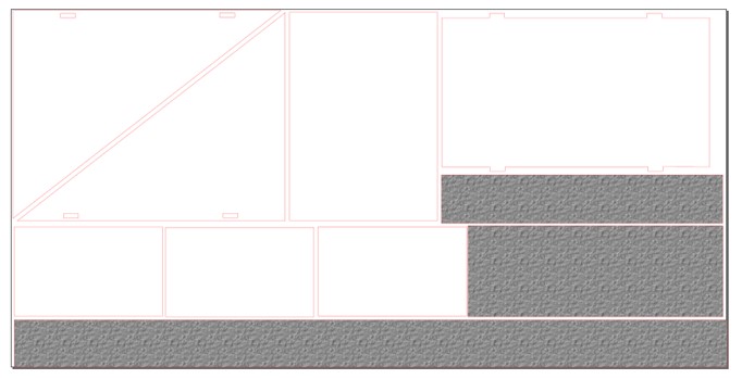
I Fixed some parts and checked the paths by using Inkscape, I added gray boxes to cut them and keep them in the scrap box for other projects.
Generate toolpaths for CNC cutting by VCarve pro software
Because of the Corona pandemic, all the labs and factories lockdown. So I downloaded a free trial of VCrave Pro, to do this assignment and I Prepared the file for cutting until we can use the CNC machine.
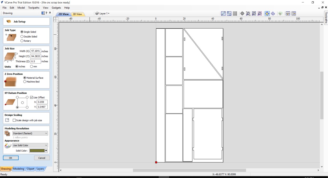
Imoprt the design as .Pdf
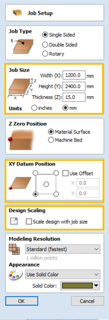
Always make sure that the job size between machine workspace. The CNC workspces that we will use is 1200x2400mm.
- Uncheck “Use Offset”.
- Uncheck “Scale design with job size”.
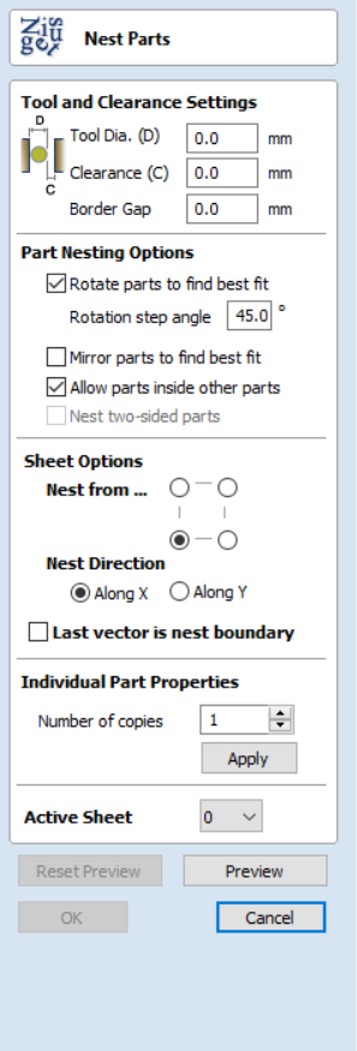
If you did not Nest the parts, the nesting can be with VCarve Pro.
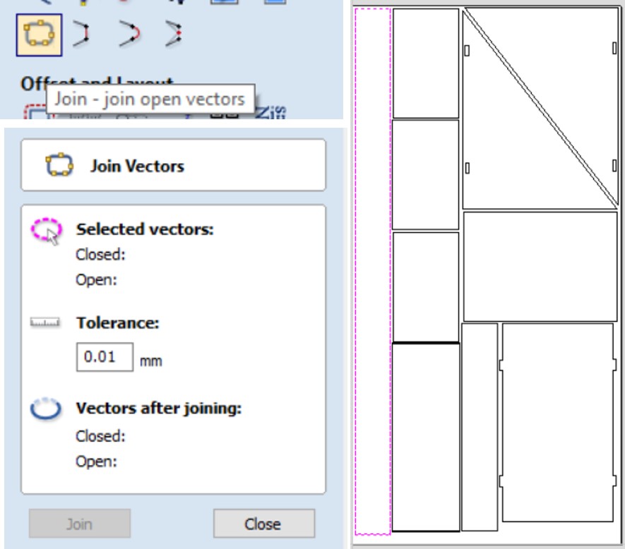
Make sure all the nods are closed you can use Join tool to close all the paths.
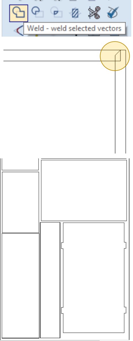
Sometime you will find some dark paths when you zoom in you will find overlap line, what I do usually, I use Weld tool to close it and delete the duplicated line, that's important to avoid cutting the paths twice.
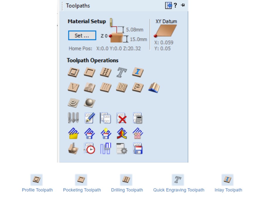
VCrave Pro allow you to do many things with the CNC machine, such as cutting, engraveing, drilling. in VCrave you will find them as:
- Profile Toolpath: Profile Machining is used to cut around or along a vector.Profile toolpaths can be outside, inside or on the selected vectors, automatically compensating for the tool diameter and angle for the chosen cut depth.
- Pocketing Toolpath:The Pocket Allowance allows you to quickly create a toolpath that will machine the pocket either smaller or larger than the defining closed vector. A Pocket Allowance of 0.0 (the default) will create a pocket the exact size of the defining vector.
- Drilling Toolpath:Drilling allows the centers of selected closed vectors to be drilled to a specified depth.
For more about 2D Profile Toolpath
Export toolpaths for CNC cutting.
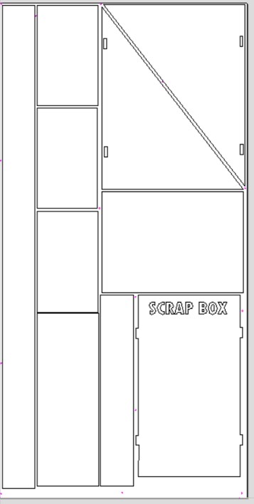
I divided the cutting orders to cut one by one. I prefer to start from inside to out.To ovide shaking or moving the outter pieces while cutting. First I will drill the workpices, then I'll cut the inner small pieces, after that I will eengrave the box name, last I will cut the box parts.
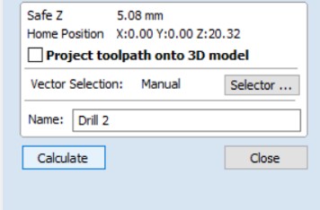
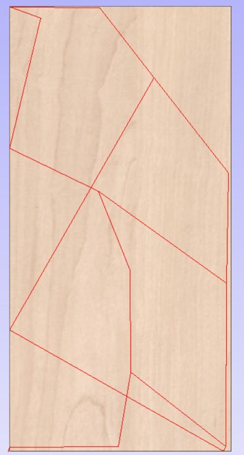
Strating generate the drill tolpath.
- Select all the circils.
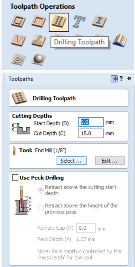
- Go to toolpaths operations, click on Drill Tolpath.
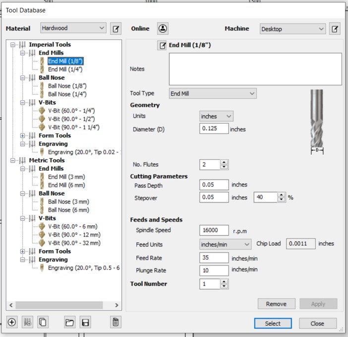
- Add the cut depth and it should match the workpice thickness, for me it will be 15mm, then choose the cut tool, I will use end mill 1/18in.
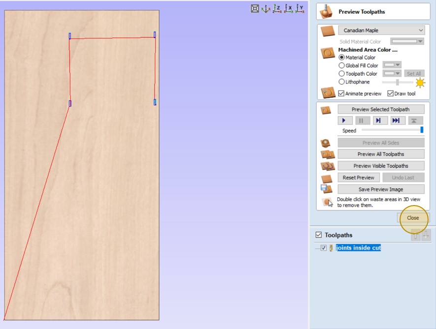
- Click on calculate to export the toolpaths.
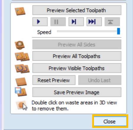
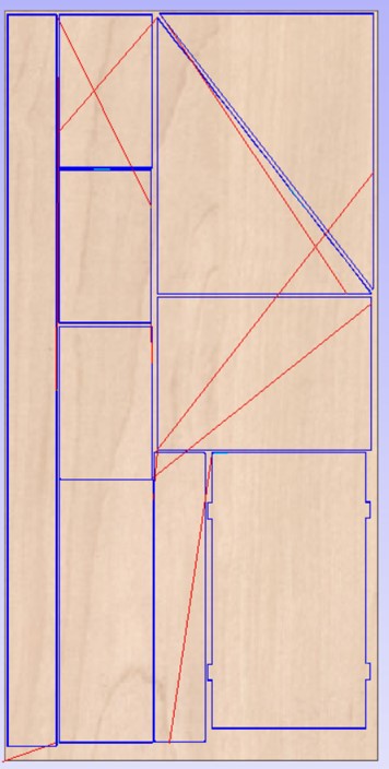
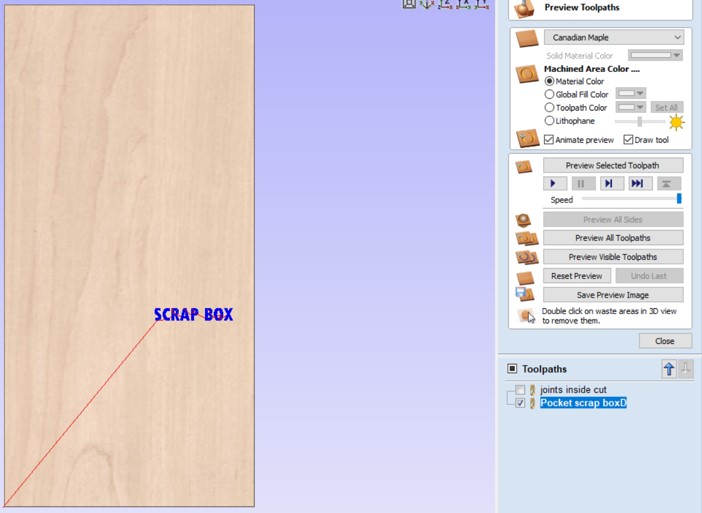
- The red lines are the machine path.
- click on Close to save the file.
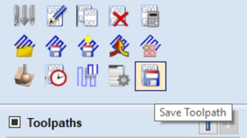
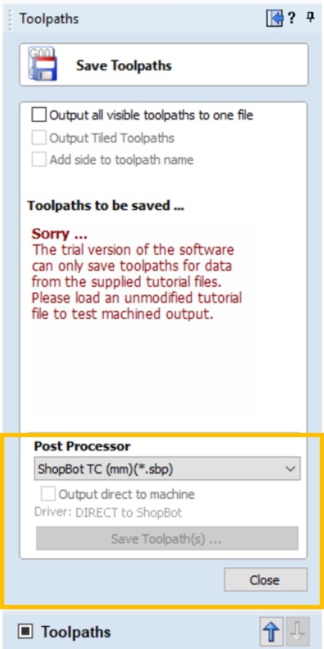
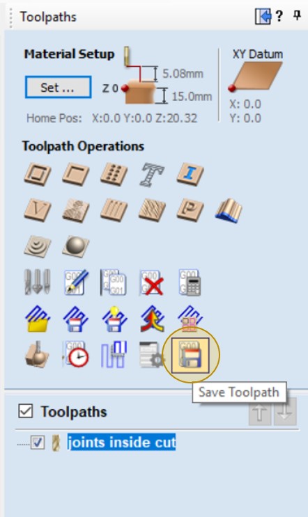
- Click on save icon.
- Make sure to select your machine model before save it. because I am using Free trail for the Vcarve pro software, I could not be able to save it. When I will be able to use the CNC, I will reapet all the steps but with lab PC.
Strating generate the cutting toolpath for the inner pieces.
- Select the inner pieces.
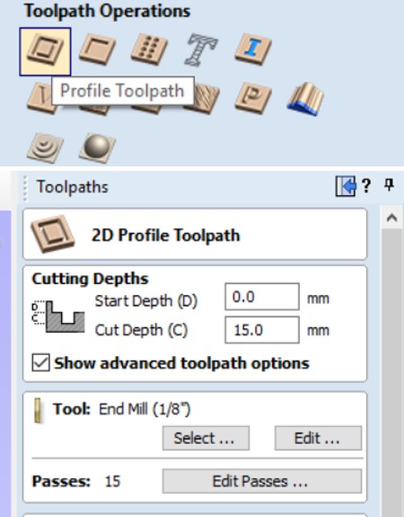
- Go to toolpath operations, click on Profile toolpath.
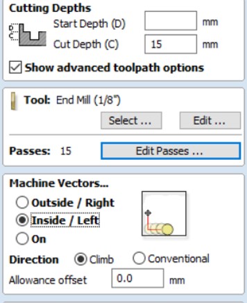
- Add the cut depth depending on material thickness, select the cutting tool, I choose end mill 1/18in.
- Then I Specify Pass Depthses.
The Pass Depths section at the top of the form shows a list of the current pass depths. The relative spacing of the passes is indicated in the diagram next to the list. Left click on a depth value in the list, or a depth line on the diagram, to select it. The currently selected pass is highlighted in red on the diagram. - Choose the machine vector, here I will cut the inner parts, iside the paths, bescause I do not need the parts and to avoide changing slots size.
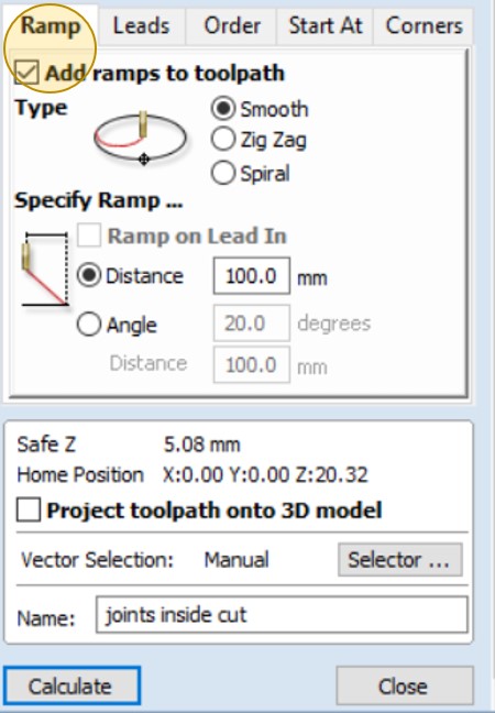
- Ramp moves are used to prevent the cutter from plunging vertically into the material. The cutter gradually cuts at an angle dropping into the material significantly reducing cutter wear, heat build-up and also the load on the router spindle and Z axis of the machine.
- Click on Close.
- Click on save icon to save the file.
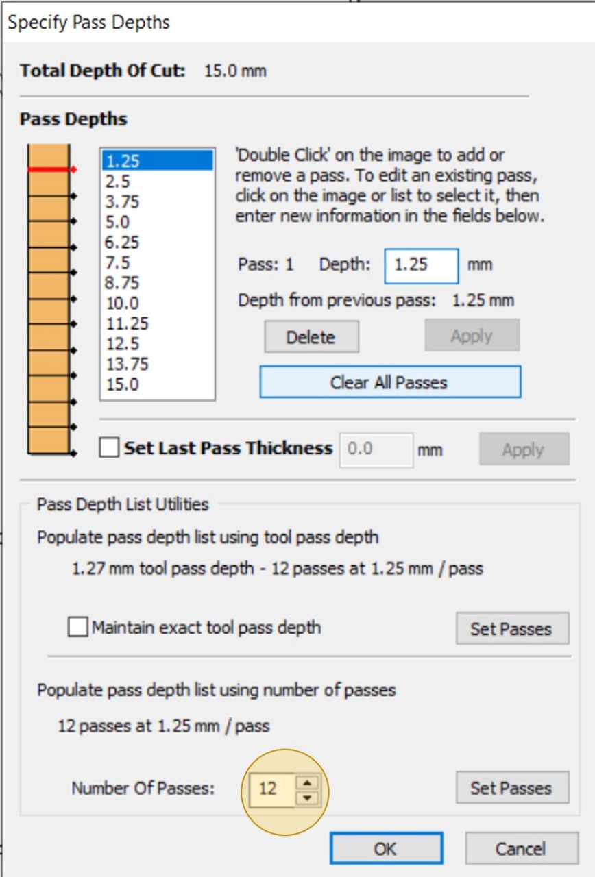
The less depth per pass, the more passes to cut.
- Select the box parts, without the slots and without the text.
- Go to toolpath operations, click on Profile toolpath.
- Add the cut depth depending on material thickness, then select the cutting tool, I choose end mill 1/18in.
- Then Specify Pass Depthses, as I did before with inner parts cutting.
- Click on calculate to generate the toolpaths.
- Click on Close.
- Click on save icon to save the file.
Strating generate the cutting toolpath for the box parts.
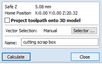
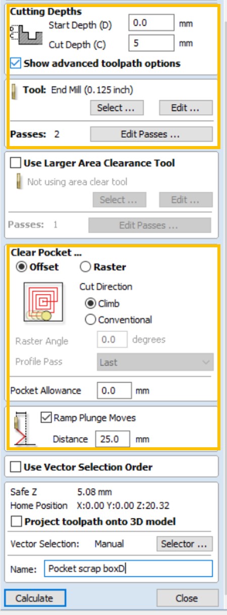
- Select only the text, without the other parts.
- Go to toolpath operations, click on Pucket toolpath.
- Add the engrave depth as you want I choose to engrave only 5mm out of 15mm -the material thickness-, then select the cutting tool, I choose end mill 1/18in.
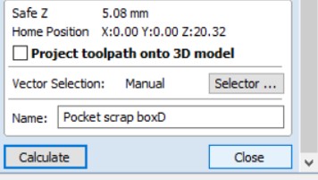
- Click on calculate to generate the Pucket toolpaths, the close.
- Click on save icon to save the file.
- The file almost ready for cutting.
Strating generate the engraving toolpath for the box name.
Some issus I face whlie genrating the tool paths:
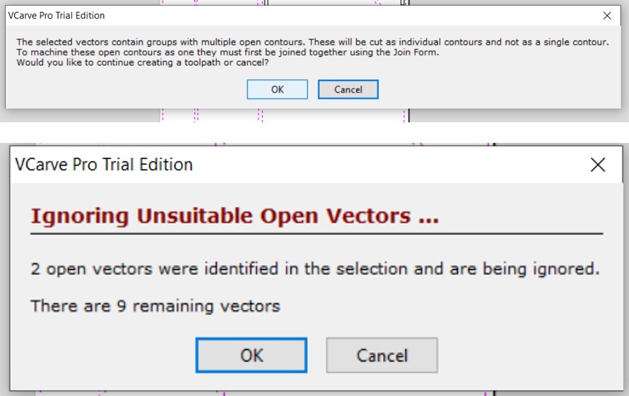
If this meesge apear click OK, and fix the part from join by using the joint tool.
Prepare the machine with correct tooling and material to cut.
Saftey FIRST!

Have your SAFETY GLASSES on. Wear EAR PROTECTION.
I will be presenting the steps for cutting and as I have been doing with other projects I did before, and I will upload pictures of the current project, until the current conditions change, and allowed us to use the lab.
When I use the CNC, I prefer to prepare the workpiece and check the table first.
- Insert the workpiece after checking the thickness.
- In our Fablab, we use screws because we have a spoil board surfacing set up, so I can screw the workpiece directly to the table. There are other ways to hold down the material for cutting, I’ll explain it later.
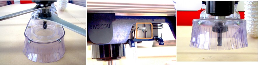
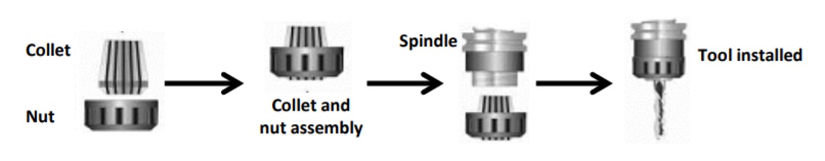
- Before I turn the CNC On, I always change the bit and make sure that the vacuum head is assembled well.
- Use the collet Wrenches and spanner tools to assemble the new bit.Turn the nut clockwise to loosen it and continue to loosen it by hand if necessary.
- Make sure the collet and the nut are completely clean. If necessary, use a wire brush, compressed air, and/or mineral spirits to remove dust or excess grease.
- Spindles: Before inserting the bit, press the collet into the nut and listen for the -click-. If collet does not seat, press it in at a slight angle.
- Confirm that the collet is snapped in by holding the nut upside-down and letting the collet hang freely.
- Thread collet and nut onto spindle. It should go on very easily. DO NOT apply force if nut is resistant.
- Stop and try again until it goes smoothly.
- Once the nut is finger-tight, check the bit again to make sure that it has not slipped. Use the included wrenches to fully tighten nut.
- Grap the scrows and the drill to holdingdown the workpice, start to drilling the corners and sides of your workpiece.
Holdingdown of ShopBot
Run the CNC machine and load toolpaths into the CNC control software - Turn on the CNC machine
- Insert key into safety lockout on the main control box, and turn key to “ENGAGED.”
- Turn on the Dust collector.
- Open the ShopBot program.
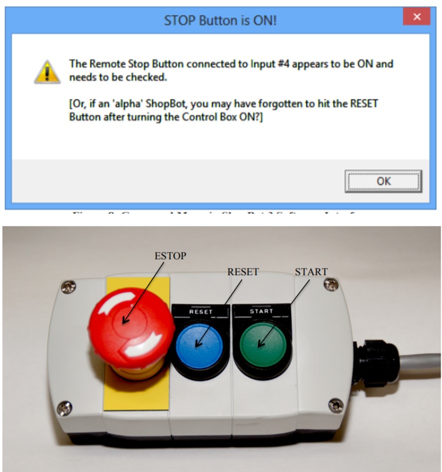
- Reset the E-stops.
- When you power up the control box you have to press the RESET button on the control box to reset the stop switch
Click OK.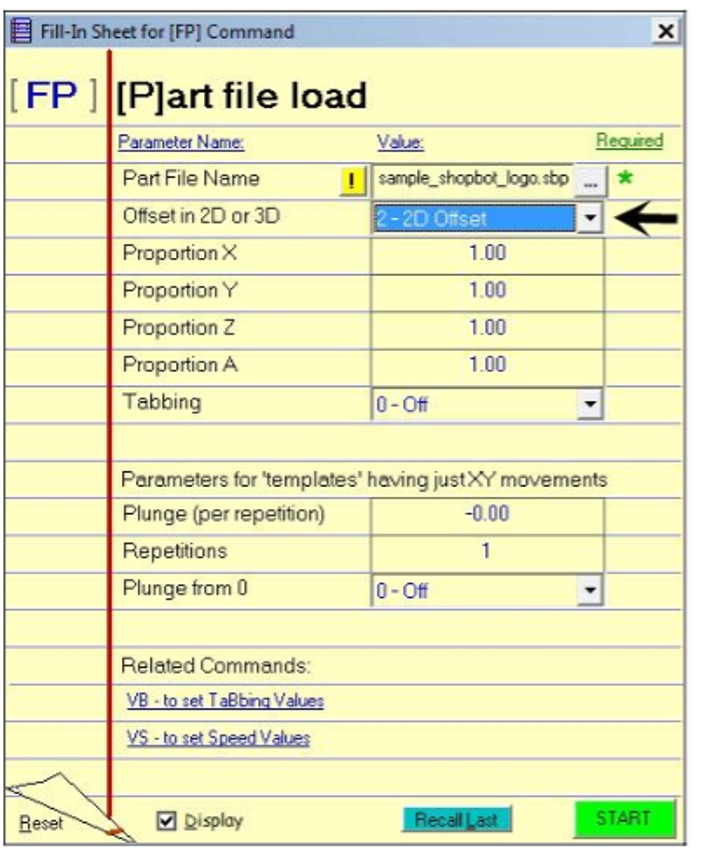
- In ShopBot program, go to File> PART LOAD> and select the ShopBot file you created ending in .SBP.
- Click Start.
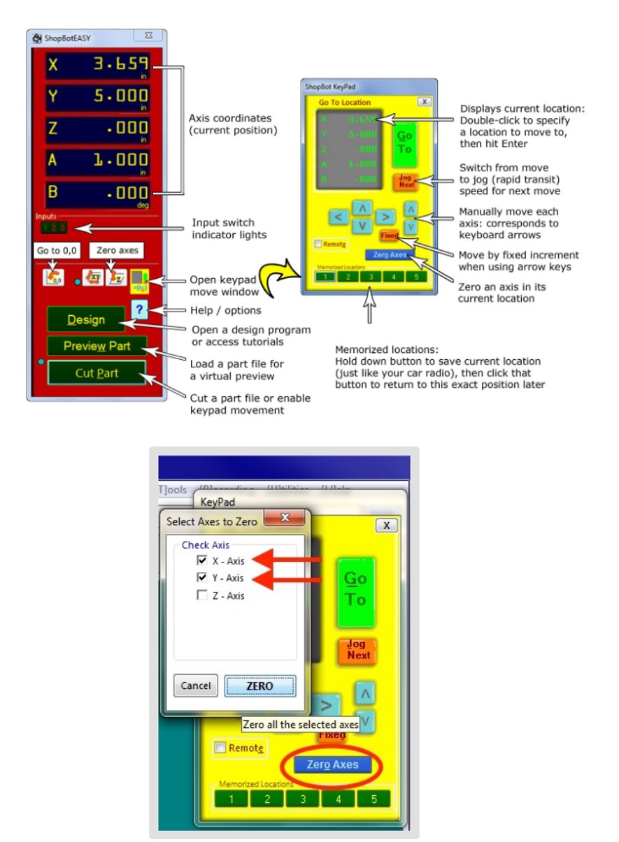
- Set the Z axis origin.
From the Zero Axes check the X Y Axis ,click ZERO.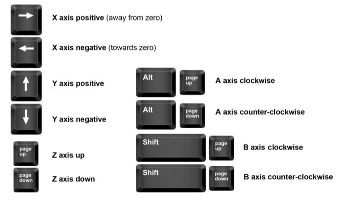
- Move the spindle to the start pion you want by using the keypad buttons, it's reflect the actual keyboard.
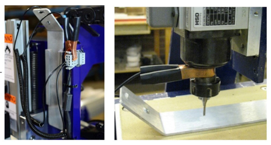
- Place the zeroing alligator clip on the collet and the plate down on the reference surface.
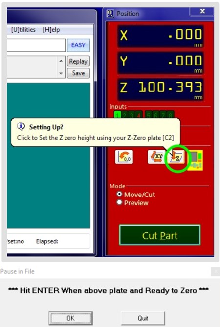
- Click OK when you are ready for the SPINDLE to go through a 2 step cycle of lowering and raising itself until it touches the aluminum PLATE twice.
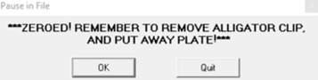
- Take back the aluminum plate and the alligator to there places.
- Click OK
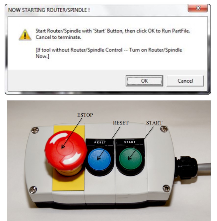
- Running the cut, FIRST press START from the E-stop buttons , BEFORE CLICK OK.
>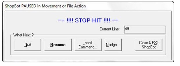
- By hitting the space bar on your keyboard. This will bring the machine to a “slow stop”and you will seethe following message: Choose Quit stop the file and go back to the main window or Resume to continue the file at this point.
Download files here:
Fabrication stage In this stage, I contact a remotely Fablab it is on another city far away 2h. after I sent the files, I faced a problem after they finished the cutting Because they don't have some cutting bit as I mentioned before on the previous stage. They used 4mm end mill bit, which affect the joints by changing the sizes. During this time still, it's not easy to access any lab, so I'll schedule an appointment soon to complete this task.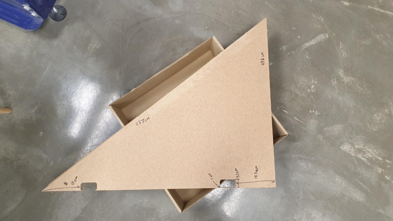
Part 1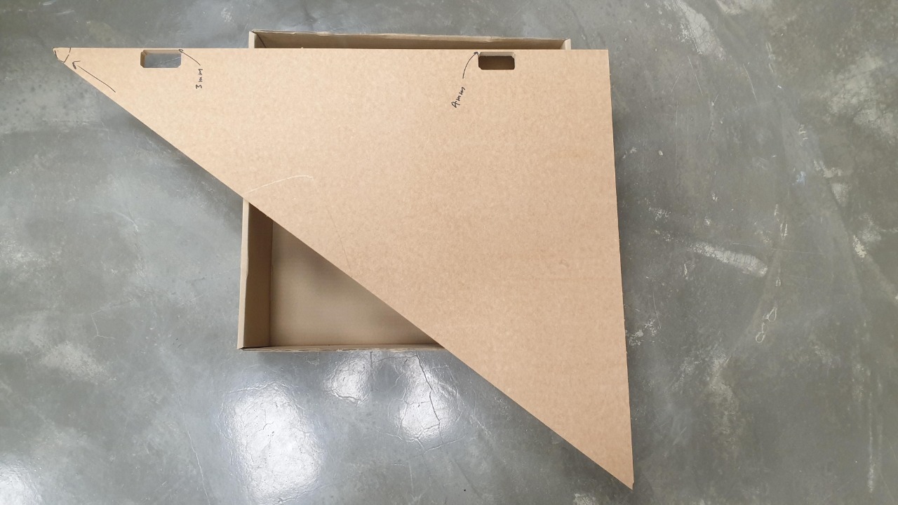
Part 2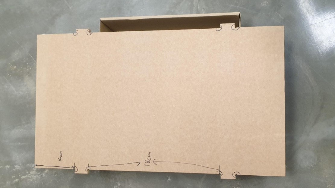
Part 3
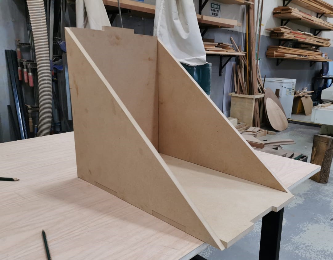
Assembled project
Group assignment:
-Test runout, alignment, speeds, feeds, and toolpaths for your machine. I did the group documentation on this page this page
Download files here:
Changing bits
For more check the links below:
Assemble Collet from ShopBot
Quick Start Guide PRSAlpha Standard